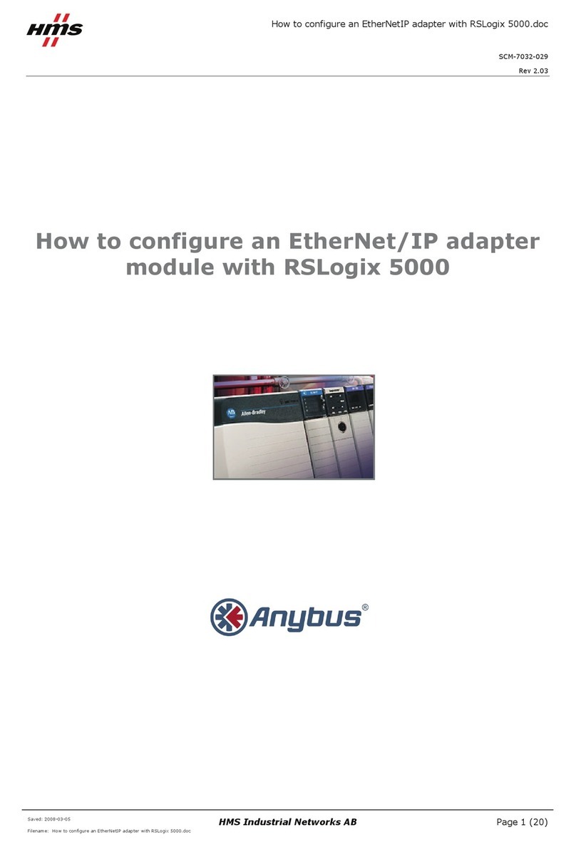
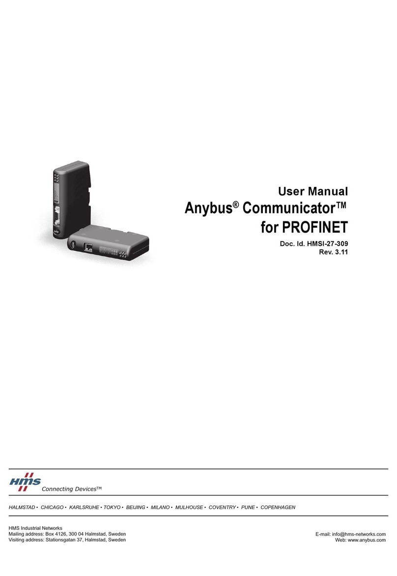
HMS CM CANopen User manual

+$/067$'&+,&$*2.$5/658+(72.<2%(,-,1*0,/$1208/+286(&29(175<381(&23(1+$*(1
HMS Industrial Networks
Mailing address: Box 4126, 300 04 Halmstad, Sweden
Visiting address: Stationsgatan 37, Halmstad, Sweden
User Manual
CM CANopen
CANopen Module for SIMATIC S7-1200
Doc.Id. HMSI-216-117
Rev. 1.00

Important User Information
This document is intended to provide a good understanding of the functionality offered by the CM CANopen Mod-
ule for SIMATIC S7-1200.
The reader of this document is expected to be familiar with high level software design, and communication sys-
tems in general. The use of advanced CANopen-specific functionality may require in-depth knowledge in CAN-
open networking internals and/or information from the official CANopen specifications. In such cases, the people
responsible for the implementation of this product should either obtain the CANopen specification to gain sufficient
knowledge or limit their implementation in such a way that this is not necessary.
Liability
Every care has been taken in the preparation of this manual. Please inform HMS Industrial Networks AB of any
inaccuracies or omissions. The data and illustrations found in this document are not binding. We, HMS Industrial
Networks AB, reserve the right to modify our products in line with our policy of continuous product development.
The information in this document is subject to change without notice and should not be considered as a commit-
ment by HMS Industrial Networks AB. HMS Industrial Networks AB assumes no responsibility for any errors that
may appear in this document.
There are many applications of this product. Those responsible for the use of this device must ensure that all the
necessary steps have been taken to verify that the applications meets all performance and safety requirements
including any applicable laws, regulations, codes, and standards
HMS Industrial Networks AB will under no circumstances assume liability or responsibility for any problems that
may arise as a result from the use of undocumented features, timing, or functional side effects found outside the
documented scope of this product. The effects caused by any direct or indirect use of such aspects of the product
are undefined, and may include e.g. compatibility issues and stability issues.
The examples and illustrations in this document are included solely for illustrative purposes. Because of the many
variables and requirements associated with any particular implementation, HMS Industrial Networks AB cannot
assume responsibility for actual use based on these examples and illustrations.
Intellectual Property Rights
HMS Industrial Networks AB has intellectual property rights relating to technology embodied in the product de-
scribed in this document. These intellectual property rights may include patents and pending patent applications
in the US and other countries.
Trademark Acknowledgements
Anybus ® is a registered trademark of HMS Industrial Networks AB.
SIMATIC®, S7-1200® and TIA® are registered trademarks of Siemens AG.
All other trademarks are the property of their respective holders.
Warning: This is a class A product. in a domestic environment this product may cause radio interference in
which case the user may be required to take adequate measures.
ESD Note: This product contains ESD (Electrostatic Discharge) sensitive parts that may be damaged if ESD
control procedures are not followed. Static control precautions are required when handling the prod-
uct. Failure to observe this may cause damage to the product.
CM CANopen Module for SIMATIC S7-1200 User Manual
Rev 1.00
Copyright© HMS Industrial Networks AB
Sep 2013 Doc Id HMSI-216-117
Preface About This Document
How To Use This Document ................................................................................................................ 1
Related Documents.................................................................................................................................. 1
Document History ................................................................................................................................... 1
Conventions & Terminology.................................................................................................................. 2
Glossary ..................................................................................................................................................... 2
Support ...................................................................................................................................................... 2
Chapter 1 Product Overview
Introduction .............................................................................................................................................. 3
Features...................................................................................................................................................... 4
Chapter 2 CANopen Fieldbus Functionality
Supported Fieldbus Services................................................................................................................... 5
Chapter 3 Transparent CAN Mode
Chapter 4 Installation
Mounting ................................................................................................................................................... 7
Status LEDs .............................................................................................................................................. 8
Maximum Cable Lengths ........................................................................................................................ 8
Line Termination...................................................................................................................................... 9
Chapter 5 Configuration
General..................................................................................................................................................... 10
SIMATIC S7-1200 PLC Configuration .............................................................................................. 10
CANopen Network Configuration ..................................................................................................... 12
Configuration Files................................................................................................................................. 12
Configuration Example ......................................................................................................................... 12
Chapter 6 CANopen Module Specification
NMT State Machine............................................................................................................................... 19
Data Exchange........................................................................................................................................ 21
PDO Functionality........................................................................................................................ 21
Error Control.......................................................................................................................................... 23
Heartbeat Mechanism.................................................................................................................... 23
Node Guarding.............................................................................................................................. 24
Emergency Object (EMCY)........................................................................................................... 24
Diagnostics .................................................................................................................................... 25
Table of Contents
Table of Contents

Table of Contents
Chapter 7 Supported Objects
Static Data Types.................................................................................................................................... 26
Communication Profile Area................................................................................................................ 26
CiA 301 Communication Profile Objects....................................................................................... 26
Configuration Manager .................................................................................................................. 29
Network Management Objects ....................................................................................................... 30
Manufacturer Specific Objects............................................................................................................. 36
I/O Buffer Addresses and Object Dictionary Indices Relation ........................................................ 41
Chapter 8 Interface Functions
CANopen Interface Functions ............................................................................................................ 43
Get Process Data In ...................................................................................................................... 43
Set Process Data Out..................................................................................................................... 44
SDO Read/Write......................................................................................................................... 45
Get Node & Network Status ....................................................................................................... 46
Transparent CAN Interface Functions............................................................................................... 48
CAN_SEND ............................................................................................................................. 48
CAN_RCV ................................................................................................................................49
CAN_CTRL .............................................................................................................................. 50
Get Diagnostic Information............................................................................................................ 52
Appendix A Technical Specification
Mechanical Properties............................................................................................................................ 54
Environmental Characteristics ............................................................................................................. 54
Regulatory Compliance ......................................................................................................................... 55
Appendix B Status LED Timing Diagrams
Appendix C CANopen Emergency Codes
Appendix D Error Codes (RET)
Function Block Error Codes ................................................................................................................ 59
Message Error Codes............................................................................................................................. 60

Doc.Id. HMSI-216-117
CM CANopen Module for SIMATIC S7-1200
Doc.Rev. 1.00
Preface
P. About This Document
P.1 How To Use This Document
This document contains a general introduction as well as a description of the technical features pro-
vided by the CM CANopen Module for SIMATIC S7-1200, including configuration of the device.
The reader of this document is expected to be familiar with PLC and software design, as well as with
communication systems in general. The reader is also expected to be familiar with the Microsoft Win-
dows operating system.
P.2 Related Documents
Please visit the support pages at the HMS Industrial Networks web site at
www.hms-networks.com/can-for-S7-1200/ for more documents
P.3 Document History
Summary of Recent Changes ( ... 1.00)
Revision List
Document name Author
CiA 301 rev. 4.2 CAN in Automation
CiA 302 Draft Standard Proposal 302 rev. 4.1 CAN in Automation
CiA 303-1 rev. 1.7 CAN in Automation
CiA 303-3 rev. 1.3 CAN in Automation
TIA Portal configuration tool user manual
Change Page(s)
Revision Date Author Chapter Description
1.00 2013-09-26 KeL All First revision

About This Document 2
Doc.Id. HMSI-216-117
CM CANopen Module for SIMATIC S7-1200
Doc.Rev. 1.00
P.4 Conventions & Terminology
The following conventions are used throughout this document:
• Numbered lists provide sequential steps
• Bulleted lists provide information, not procedural steps
• The term ‘user’ refers to the person or persons responsible for installing the CM CANopen mod-
ule in a network.
• Hexadecimal values are written in the format NNNNh, where NNNN is the hexadecimal value.
• Decimal values are represented as NNNN where NNNN is the decimal value
• A byte always consists of 8 bits
P.5 Glossary
P.6 Support
For general contact information and where to find support, please refer to the contact and sup-
port pages at www.hms-networks.com.
Term Meaning
Byte 8 bits
COP CANopen
User Person or persons responsible for installing the CM CANopen module
Higher Level Network CANopen
Network
Fieldbus
RO Read only. A register, parameter or object labeled RO can only be read, not written.
RW Read/Write. A register, parameter or object labeled RW can both be read and written
EDS Electronic Data Sheet. A file that describes the properties of a network device, in this case a
CANopen device.

Doc.Id. HMSI-216-117
CM CANopen Module for SIMATIC S7-1200
Doc.Rev. 1.00
Chapter 1
1. Product Overview
1.1 Introduction
The CM CANopen Module for SIMATIC S7-1200 is a plug-in IP20 compliant communication module
designed to be used as an accessory to a SIMATIC S7-1200 PLC. It provides the user with the possibility
to connect a CANopen network to a SIMATIC S7-1200 PLC.
The figure below shows a CM CANopen module attached to a SIMATIC S7-1200 PLC to provide the
connection from the PLC to CANopen. In this case the PLC is standalone, but it is possible to connect
it to a PROFINET network.
The CM CANopen Module for SIMATIC S7-1200 can be configured either as a CANopen manager or
as a slave, depending on the application. The network and the module are configured using external con-
figuration tools (TIA Portal and CM CANopen Configuration Studio). See “Configuration” on page 10.
CANopen
CM CANopen module
Slave devices on the CANopen network

Product Overview 4
Doc.Id. HMSI-216-117
CM CANopen Module for SIMATIC S7-1200
Doc.Rev. 1.00
1.2 Features
• Powerful CANopen module for SIMATIC S7-1200 PLC.
• 3 modules per CPU can be connected.
• Connects up to 16 CANopen slave nodes per module in manager mode.
• 256 byte input and 256 byte output per module.
• CANopen slave functionality supported.
• 3 LEDs provide diagnostic information on module, network and I/O status.
• The module can be integrated in the hardware catalogue of TIA Portal.
• CANopen configuration via CM CANopen Configuration Studio (external tool).
• Complies to the CANopen communication profile CiA 301 rev. 4.2 and the CiA 302 Draft
Standard Proposal rev. 4.1.
• Transparent CAN supported.

Doc.Id. HMSI-216-117
CM CANopen Module for SIMATIC S7-1200
Doc.Rev. 1.00
Chapter 2
2. CANopen Fieldbus Functionality
The functionality of the CM CANopen Module for SIMATIC S7-1200 is defined by the CANopen CiA
301 rev. 4.2 specification and the CANopen CiA 302 Draft Standard Proposal rev. 4.1. The module can
be configured either as a manager or as a slave on the CANopen network.
2.1 Supported Fieldbus Services
Communication and parameters in the CANopen protocol are built around objects. There are different
services available to communicate with the objects and to perform other CANopen tasks like supervis-
ing the network. The following message types and objects are implemented in the CM CANopen Mod-
ule for SIMATIC S7-1200:
• NMT (Network Management)1messages trigger the NMT state transitions for the slaves and/
or perform network and device monitoring, as well as handle errors. If the module is configured
as a slave, startup is performed by the manager.
• The CMT (Configuration Manager)1configures the CANopen devices. This primarily involves
PDO parameters and mapping of information. If the module is configured as a slave, the con-
figuration is performed by the manager.
• PDOs (Process Data Objects) are used for I/O communication. There are 64 Receive PDOs and
64 Transmit PDOs implemented in the CM CANopen Module for SIMATIC S7-1200 that each
can transfer up to 8 bytes. Supported PDO message types are event driven (COS or timing), Cy-
clic Synchronous and Acyclic Synchronous
• SDOs (Service Data Objects) are asynchronous data transmission, and are used to access objects
without mapping them to an I/O (PDO) connection. Access is provided to all CANopen objects
in the module and in the network nodes (manager mode). SDO messages are used to configure
the modules and they can transfer more than 8 bytes, which is the upper limit for a PDO. (Ex-
pedited Upload/Download Protocol and Normal (Segmented) Upload/Download Protocol are
supported)
• A SYNC (Synchronization Object) is used for synchronizing PDO communication. A manager
can be either a producer or a consumer of the synchronization. A slave can only be a consumer.
• The Heartbeat Mechanism helps a device to monitor the status of another node. The module can
act either as heartbeat producer or consumer or both at the same time.
• The Node Guarding Protocol provides active surveillance of a slave by the manager. Slaves can
be configured to expect a node guarding request from the manager.
• An EMCY (Emergency Object) is used for error reporting when a fault has occurred in the mod-
ule and for reporting when all faults in a module have been cleared.
1. Only available when the module is configured as manager.

Doc.Id. HMSI-216-117
CM CANopen Module for SIMATIC S7-1200
Doc.Rev. 1.00
Chapter 3
3. Transparent CAN Mode
The CM CANopen Module for SIMATIC S7-1200 integrates Transparent CAN 2.0A (11 bit identifiers).
With this protocol, the module allows transmission of any CAN frame from the PLC regardless of the
overlaying CAN protocol, and is capable of receiving a number of predefined CAN frames from the
CAN network. No other functionality is available.
CAN 2.0A is the underlying protocol of CANopen, directly working on the bus. During configuration
in TIA Portal, Transparent CAN can be selected in the Options menu. When this configuration is down-
loaded to the module, the CANopen functionality is not possible to use. If CANopen functionality is to
be reactivated, a new configuration from TIA Portal will have to be downloaded. It is not possible to
change between CAN and CANopen at runtime.
Each CAN frame is tagged with an identifier. Only received frames with an identifier specified by the
function block CAN_CTRL will be forwarded to the PLC. The data in the frame is then available for
the user to interpret. When sending a frame, the user specifies the data and adds a valid identifier before
sending it to the module.
To facilitate the use of Transparent CAN, separate PLC function blocks are available1. They are de-
scribed in “Transparent CAN Function Blocks” on page 47. The blocks give the designer of the PLC
program the possibility to integrate Transparent CAN functionality (sending, receiving, configuration)
into the PLC program, thereby making it possible to implement customer specific CAN protocols.
Note: The receive buffer can hold up to 256 unread received messages
1. The function blocks can be downloaded from www.hms-networks.com/can-for-S7-1200.

Doc.Id. HMSI-216-117
CM CANopen Module for SIMATIC S7-1200
Doc.Rev. 1.00
Chapter 4
4. Installation
The mounting and configuration of the CM CANopen Module for SIMATIC S7-1200 is done following
these steps:
1. Mounting
2. Configuring the SIMATIC S7-1200 PLC to use the module (See “SIMATIC S7-1200 PLC Con-
figuration” on page 10)
3. Setting the parameters of the module (See “SIMATIC S7-1200 PLC Configuration” on page 10)
4. If in a CANopen operation mode, configuring the CANopen network, including the module (See
“CANopen Network Configuration” on page 12)
The following items are needed to perform the installation:
• TIA Portal V11, SP2 or later
• HSP (configuration file) for the module1
• CM CANopen Configuration Studio
• Function blocks (optional)1
4.1 Mounting
The CM CANopen Module for SIMATIC S7-1200 is designed to be connected di-
rectly to a SIMATIC S7-1200 PLC.
CANopen connection is provided via a DSUB contact.
A new module is configured from scratch, using TIA Portal and CM CANopen Configuration Studio.
See also:
•“CANopen Network Configuration” on page 12
1. Can be downloaded from www.hms-networks.com/can-for-S7-1200
No. Name Description
2 L CAN_L, low level in CANopen communication
3, 6 GND Ground, provides connections to the CANopen network ground
5SHLD Shield, provides connection to the CANopen network shield
7 H CAN_H, high level in CANopen communication
1, 4, 8, 9 N.C. Not connecteda
a. To ensure backwards compatibility, these contacts should not be connected.
15
96
(male)

Installation 8
Doc.Id. HMSI-216-117
CM CANopen Module for SIMATIC S7-1200
Doc.Rev. 1.00
4.2 Status LEDs
Three status LEDs indicate the status of the module as shown in the table be-
low. The DIAG LED is visible on the front of the module and the other two
are found behind the lid at the top of the module. The behavior of the LEDs
is described in “Status LED Timing Diagrams” on page 56
4.3 Maximum Cable Lengths
When designing the CANopen network, please take into account the maximum cable length for differ-
ent baud rates.
LED Indication Status
DIAG (red/green) Green Normal operation
Blinking green Hardware address not configured yet
Blink red CM bus error state.
Note: This LED only report errors on the
CM backplane bus. Diagnostic errors are
indicated by the error LED on the PLC.
ERR - CANopen
error (red)
Off Normal operation
Blinking General configuration error
Single flash Warning limit reached in CAN controller, for
example due to bad or no signal on the
CANopen network.
Double flash A nodeguard event or a heartbeat event
has occurred.
Triple flash Sync error. The sync message has not
been received within the configured com-
munication cycle time
1 Hz Fatal error, contact support.
On The CAN controller is bus off.
RUN - CANopen
state (green)
Off No power, not configured or no CANopen
network
Blinking Pre-operational
Single flash Stopped
Triple flash Transparent CAN mode
On Operational
Baud rate (kilobaud) Maximum cable length (m)
20 2500
50 1000
125 500
250 250
500 100
800 50
1000 25

Installation 9
Doc.Id. HMSI-216-117
CM CANopen Module for SIMATIC S7-1200
Doc.Rev. 1.00
4.4 Line Termination
To minimize the signal’s reflections from the end of the cable, a line termination is needed close to each
end of the bus. If the cable you are using is not terminated, connect a line termination between contacts
2 and 7 (CAN_L and CAN_H) beneath the slot, where the module is mounted. The impedance of the
termination should be 120 (5%, 1/4 W max.).

Doc.Id. HMSI-216-117
CM CANopen Module for SIMATIC S7-1200
Doc.Rev. 1.00
Chapter 5
5. Configuration
5.1 General
Configuration of the SIMATIC S7-1200 PLC to provide connectivity to a CAN/CANopen network,
using the CM CANopen Module for SIMATIC S7-1200, can be done in different ways, depending on
the application.
The CANopen network, and the behavior of the module on this network, have to be configured using
an external CANopen configuration tool on the PC and the configuration is downloaded to the CM
CANopen module through the module USB connection.
The module can be configured either as a manager or as a slave, depending on the application.
5.2 SIMATIC S7-1200 PLC Configuration1
Siemens TIA Portal is used to configure the SIMATIC S7-1200 PLC and the CM CANopen Module for
SIMATIC S7-1200. The module can be imported into the tool.
The CM CANopen module offers the SIMATIC S7-1200 PLC access to a CAN/CANopen network,
where the CM CANopen module either acts as a Transparent CAN module or acts as a slave or a man-
ager on a CANopen network, depending on the settings in the parameter list. The SIMATIC S7-1200
may act as a PROFINET slave, with another PLC on the PROFINET network as master. If so, the SI-
MATIC S7-1200 together with the CM CANopen module can act as a gateway between PROFINET
and CANopen.
A example on how to configure the system is given on page 12.
1. The configuration procedure in TIA Portal is the same for CANopen and CAN networks.
CANopen
CM CANopen module
Slave devices on the CANopen network
PC with
tools
LAN (PROFINET)
USB

Configuration 11
Doc.Id. HMSI-216-117
CM CANopen Module for SIMATIC S7-1200
Doc.Rev. 1.00
Double-clicking on the CM CANopen Module for SIMATIC S7-1200 in the list of modules in TIA Por-
tal will open a window, where the user can set the values of the module parameters.
The following parameters, that have to be defined, can be found in the CANopen Interface tab:
The parameterization is downloaded to the PLC with the HW configuration, using an Ethernet connec-
tion.
Parameter Description Values Default value
Node number Node-ID on the CANopen network.
Allowed values are 1 - 127
1-127 1
Operating mode The operating mode of the module can be changed at any
time using this parameter.
Transparent CAN
CANopen Manager
CANopen Slave
CANopen Man-
ager
Baudrate This parameter defines the baud rate on the CAN network. 20 kbit/s
50 kbit/s
125 kbit/s
250 kbit/s
500 kbit/s
800 kbit/s
1000 kbit/s
500 kbit/s
CANopen input
data sizea
a. Only valid in CANopen mode
This parameter defines the CANopen input data size. The
direction is defined from the CANopen network point of view,
that is input is input to the module from the CANopen net-
work. Possible values are 1 - 256 bytes.
1 - 256 32
CANopen output
data sizea
This parameter defines the CANopen output data size. The
direction is defined from the CANopen network point of view,
that is output is output to the CANopen network from the
module. Possible values are 1 - 256 bytes.
1 - 256 32
CANopen Man-
ager auto config-
urationb
b. Only valid in CANopen manager mode
Auto configuration scans the network for devices at startup
and tries to start them. Default PDO mapping is used. Auto
configuration is enabled by checking a box in the configura-
tor.
Disabled
Enabled
Disabled

Configuration 12
Doc.Id. HMSI-216-117
CM CANopen Module for SIMATIC S7-1200
Doc.Rev. 1.00
5.3 CANopen Network Configuration
An external CANopen configuration tool1is used to configure the nodes on the CANopen network.
The resulting Concise DCF files are downloaded to the CANopen manager using a USB connection be-
tween the PC and the CM CANopen module. At the next startup the CANopen manager will configure
the network, if this function was set in the configuration tool during initial configuration.
The CM CANopen Module for SIMATIC S7-1200 can be configured either as a manager or as a slave
on the CANopen network. The configuration is decided by the PLC (by the Parameterization values).
5.4 Configuration Files
The Electronic Data Sheet (EDS) file for the CM CANopen Module for SIMATIC S7-1200 will be au-
tomatically installed with the CANopen configuration tool. This file is necessary to perform the config-
uration of the module on the CANopen network. Updated versions will be available at www.hms-
networks.com/can-for-S7-1200.
The necessary information for configuring the module with the SIMATIC S7-1200 PLC can be included
in TIA portal by installing the HSP file2.
5.5 Configuration Example
This section gives an example of a TIA Portal configuration of the CM CANopen module from HMS
Industrial Networks in combination with the S7-1200 PLC from Siemens. In this example a CPU of type
1214C is used, but the example can be applied to all other PLC types as well. To run this example, the
HSP file, that can be downloaded from www.hms-networks.com/can-for-S7-1200, must have been in-
stalled.
1. Please visit www.hms-networks.com/can-for-S7-1200 or contact HMS support for further information, see “Support” on page 2.
2. Available for download at www.hms-networks.com/can-for-S7-1200.

Configuration 13
Doc.Id. HMSI-216-117
CM CANopen Module for SIMATIC S7-1200
Doc.Rev. 1.00
1. Open the TIA Portal program and start a new project by clicking “Create new project” on the
left side of the screen.
2. Enter a name for the project and the path to where the project should be stored, optionally with
information like author and descriptive comments. Press “Create”.

Configuration 14
Doc.Id. HMSI-216-117
CM CANopen Module for SIMATIC S7-1200
Doc.Rev. 1.00
3. Select “Devices & networks” to the left and then press “Add new device”.
4. Select the PLC type used in the configuration. Select correct software version and optionally en-
ter a name for the PLC (default PLC_1). Press “Add”.

Configuration 15
Doc.Id. HMSI-216-117
CM CANopen Module for SIMATIC S7-1200
Doc.Rev. 1.00
5. Select the CM CANopen module in the list as shown in the picture. Drag and drop an instance
of the module to the left side of the PLC module.
6. Double click on the Ethernet connector on the PLC and enter a proper IP address for the PLC.

Configuration 16
Doc.Id. HMSI-216-117
CM CANopen Module for SIMATIC S7-1200
Doc.Rev. 1.00
7. Double click on the connector of the CM CANopen module and choose the module parameter
tab. Enter the values in the parameter list. Please note that these parameters are valid for the
module on the CANopen network.
In this example, the CM CANopen module for S7-1200 is configured as a CANopen manager.
The node number on the CANopen network is 1. The CANopen baud rate is set to 500 kbit/s
and both the input data size and the output data size are set to 32 bytes.
8. The configuration is now finalized and can be downloaded to the S7-1200 device. To download
the software configuration select the PLC_1 on the right and choose “Online” > “Download to
device”. To download the hardware configuration, right-click on the device in the tree and
choose “Download to device” > “all”.
Table of contents
Other HMS Control Unit manuals

HMS
HMS Anybus User manual

HMS
HMS Anybus AS-Interface Master User manual

HMS
HMS Anybus Communicator User manual

HMS
HMS Anybus EtherNet/IP User manual

HMS
HMS Anybus CC-Link Slave Setup guide

HMS
HMS IXXAT Safe T100 Installation and operating manual

HMS
HMS Ixxat USB-to-CANV2 User manual

HMS
HMS Ewon Flexy FLB 3205 User manual

HMS
HMS Anybus CompactCom 30 Guide

HMS
HMS Anybus CANopen Slave User manual
Popular Control Unit manuals by other brands

SSS Siedle
SSS Siedle NG 602-01 Product information

KEBCO
KEBCO COMBIVERT H6 Series Instructions for use

EG&G
EG&G ORTEC 426 Operating and service manual

Genebre
Genebre 2100 Installation, operation and maintenance manual

TLV
TLV LV6 Series instruction manual

Carlin
Carlin 70200 Installation and operating instructions