Dantel 46017 User manual

CAUTION
•Install or remove modules from the shelf only when the power is off.
If you install a module in the shelf with the power on, the internal
circuitry may suffer damage and the product warranty will be void.
•Remove and install circuit boards only in a static-safe environment
(use antistatic wrist straps, smocks, footwear, etc.).
•Keep circuit boards in their antistatic bags when they are not in use.
•Do not ship or store circuit boards near strong electrostatic, electromag-
netic, magnetic, or radioactive fields.
•For more complete information on electrostatic discharge safety
precautions, refer to BellcoreTM Technical Reference # TR-NWT-000870.
Copyright 1998 by Dantel, Inc. • Dantel is a registered trademark of Dantel, Inc. • ISO 9001 Registered
Printed in the U.S.A.
INSTALLATION & OPERATION MANUAL
46017-0398 <90-00006>
46017
SUMMARY AUDIBLE ALARM
MODULE (SAAM)
About this Practice:
This practice has been reissued to:
• Move the Applications Information
section forward.
Issue date: March 1998
Reissued Practices: Updated and
new content can be identified by a
banner in the right margin.
UPDATED
Table of Contents
Ordering Information ........................................................................... 2
General Description.............................................................................. 2
Circuit Description ............................................................................... 3
Application Information ....................................................................... 6
Installation.......................................................................................... 10
Operation ............................................................................................ 13
Technical Specifications ..................................................................... 14
Warranty ............................................................................................. 16
46017-00
SUMMARY
AUDIBLE ALARM
ON
ACO
EXIST
NEW
ACK
ON
ACO
EXIST
NEW
ACK
ON
ACOACK
A11-46017-00 REV__
GROUP 1
GROUP 2

PAGE 2 46017-0398 <90-00006>
NOTE: This section lists the different options available for this product. To order any of the avail-
able options, contact Dantel Inside Sales through our toll-free number, 1-800-432-6835.
OPTION NUMBER FEATURES
A11-46017-01 Summary Audible Alarm Module (SAAM)
A11-46017-11 Summary Audible Alarm Module (SAAM)
ORDERING INFORMATION
The 46017 Summary Audible Alarm Module (SAAM) provides
a highly recognizable two-level audio alarm indicator and
alarm status display to alert service personnel of an alarm. The
module is part of Dantel’s 460 Alarm and Control System.
The 46017 SAAM indicates alarms audibly and visually, re-
motely or locally. It accepts 16 external alarms, summed in two
groups of eight. Each group of eight alarms reports with a
different tone rate, allowing priority alarms to be grouped
together and audibly recognized.
The 46017 SAAM also provides relays to control external audio
and visual alarm indicating devices.
A timer can be set to acknowledge all alarms automatically.
There are two options of the module:
46017-01 - The first four inputs of each group are TTL as well as
optically coupled (OC) inputs. The second four inputs of each
alarm group are OC only.
46017-11 - The same as the 46017-01 except that inputs 5
through 8 of Alarm Group 1 and inputs 13 through 16 of Alarm
Group 2 are TTL inputs instead of OC inputs.
The 46017 SAAM is a plug-in printed circuit module that fits
into any Dantel 400-type or similar equipment housing. It
operates on -21 to -56 VDC input power.
The front panel includes:
♦Two status-indicating LEDs for each alarm input
♦A Sonalert audible alarm with Alarm Cut-Off (ACO) switch
and LED
♦Alarm acknowledge buttons for each alarm group
♦Alarm Cut-Off (ACO) switches
♦LEDs for external alarm indicating devices for each alarm
group
♦An external Alarm Acknowledge button
GENERAL DESCRIPTION

46017-0398 <90-00006> PAGE 3
CIRCUIT DESCRIPTION
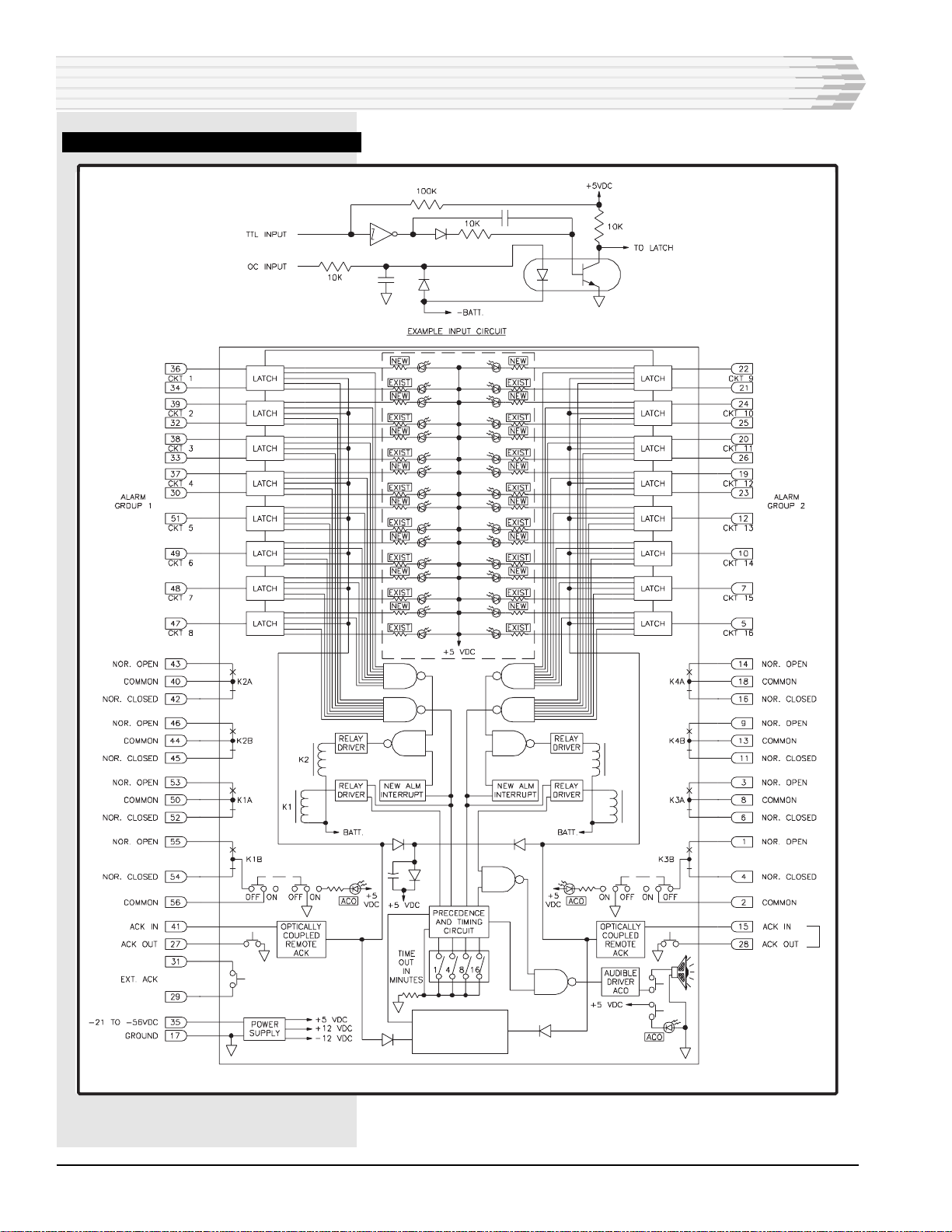
Afunctional schematic for the 46017 Summary Audible
Alarm Module is shown in Fig. 1. Here is a brief description
of each of the functional parts of the circuit:
Input Latching Circuits
There are 16 alarm input circuits. Each one has an input latch-
ing circuit that remains inactive with a high state present until
an alarm is indicated (when an input goes to ground). When an
alarm occurs, even momentarily, the input latch circuit holds
(latches) its output to the alarm summing logic.
When an alarm comes in, two front panel LEDs light. The LED
labeled EXIST follows the input signal, but the NEW LED is
held by the latch circuit until someone acknowledges the alarm.
When alarms are acknowledged, the NEW LEDs go out. There
are four ways to acknowledge alarms:
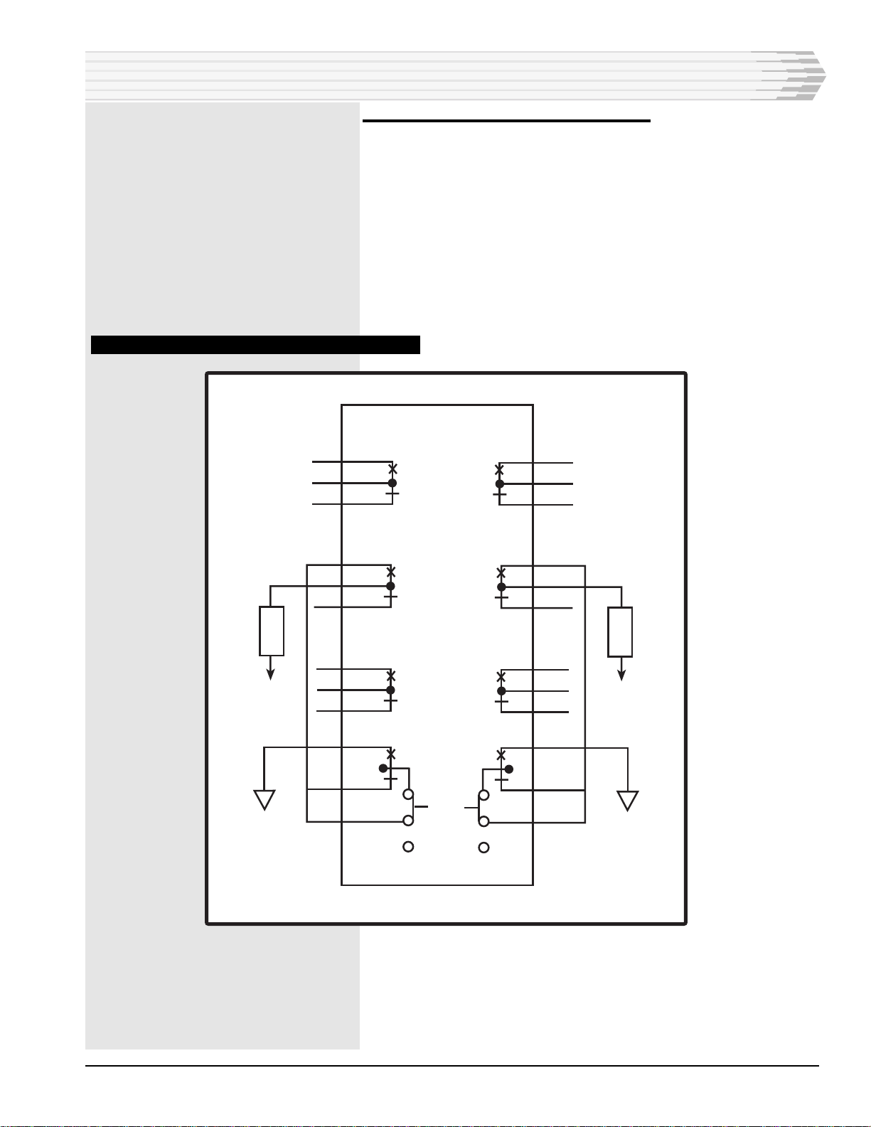
♦Push the front panel acknowledge (ACK) buttons in factory-
wired applications. Pins 27 and 41 for Alarm Group 1, and
pins 15 and 28 for Alarm Group 2 are normally wired to-
gether at the factory to enable the buttons to operate.
♦Connect pin 41 for Alarm Group 1 and pin 15 for Alarm
Group 2 to a remote ground source.
♦Connect pin 29 of the EXT ACK to ground. Connect pin 31 to
pins 41 and 15 of 46017 modules. Pressing the EXT ACK
button will acknowledge alarms on the 46017 SAAM and all
modules to which the switch is wired.
♦Set the DIP switches to acknowledge alarms automatically
after a certain time-out period (refer to Table A).
Alarm OR’d Logic
There are two groups of eight inputs combined by the alarm
logic circuit (called alarm OR’d logic). One or more inputs results
in an output to the relay select and driver circuits.
If an alarm signal is present at the alarm OR’d logic and another
alarm signal from the same group comes in, its front panel
LED lights to indicate the additional alarm. The audio alarm
tone rate does not change. However, if the first alarm is from
Group 1 and the second is from Group 2, the Group 2 alarm
takes precedence over the Group 1 alarm. In that case, the audio
alarm rate changes and the device generates a different tone.
Relay Select and Driver Circuit
The alarm signal from each group’s OR’d logic goes to the relay
select and driver circuit to activate relays. Each relay coil
operates two sets of form-C contacts. Refer to Table A.
The NEW relays deactivate when you acknowledge an alarm.
The EXIST relays follow the alarm input. If alarms still exist
when they are acknowledged, the NEW relays deactivate but the
EXIST relays do not.
RELAY COILS
K1 AND K2
Activated by Alarm Group 1.
K3 AND K4
Activated by Alarm Group 2.
K1 AND K3
Activated by a new alarm.
K2 AND K4
Activated by an existing
alarm.
TABLE A - RELAY COILS

PAGE 4 46017-0398 <90-00006>
FIG. 1 - FUNCTIONAL SCHEMATIC, 46017
K4
K3
AUTOMATIC
ALARM
ACKNOWLEDGEMENT
CIRCUIT
TTL
OC
TTL
OC
TTL
OC
TTL
OC
OC
OC
OC
OC
TTL
OC
TTL
OC
TTL
OC
TTL
OC
OC
OC
OC
OC
CIRCUIT DESCRIPTION

46017-0398 <90-00006> PAGE 5
Precedence and Timing Circuit
The precedence and timing circuit receives alarm signals from
the OR’d logic and sets the alarm group precedence (Alarm
Group 2 always has precedence). This provides two advantages:
♦It prevents more than one alarm at a time from turning on
the audible alarm
♦It provides a different output signal for each alarm group:
Group 1 - two seconds on, one second off
Group 2 (with precedence) - one second on, one
second off
Alarms can be acknowledged automatically after a time-out of 1,
4, 8 or 16 minutes. The time-out disables the audible alarm,
turns off any NEW alarm LEDs, and releases relays K1 and K3.
After the time-out period, any new alarms will reactivate the
relays and audible alarm, and restart the timer. When the time-
out function is not used, the relays and audible alarm remain
active until you acknowledge the alarms.
Audio Driver and ACO
When a NEW alarm comes in, the output from the precedence
and timing circuit turns on the audio driver. The audio driver
powers the audible alarm, and the sound alerts service person-
nel of the alarm condition.
On the front panel an ACO (Alarm Cut-Off) switch shuts off the
audible portion of the alarm reporting. A front panel LED
remains on as long as the ACO switch is on. This LED serves to
remind service personnel that the audio has been shut off and
they will not hear subsequent alarms.
Power Supply
The power supply operates on -21 to -56 VDC input power. It
supplies regulated +5 VDC as well as +12 and -12 VDC power to
the 46017 module’s circuits.
CIRCUIT DESCRIPTION

PAGE 6 46017-0398 <90-00006>
APPLICATION INFORMATION
This section describes four example applications: Multiple
Level, Single Level, Single or Multiple Level, and External
Device.
Multiple-Level Application
Fig. 2 shows a multiple-level alarm reporting application using
46009 and 46010 Multiple Alarm Transmitters (MATs). The
46017 SAAM optically coupled inputs connect to the MAT alarm
bus outputs. This application can use up to 8 MATs.
The 46017 SAAM reports alarms on only two levels. Group 2
always precedes Group 1. Connect a second 46017 SAAM for
additional alarm level inputs.
Each of the four groups provides a different audio and/or visual
signal. Two groups use the 46017 SAMM on-board Sonalert. The
other two control an external audio or visual device with their
alarm-enabled relays (K1-B, pins 56 and 54 or 55 in Group 1,
and K3-B, pins 2 and 1 or 4 in Group 2). Setting the ACO switch
to ON disables the Sonalert.
FIG. 2 - MULTIPLE-LEVEL ALARM REPORTING APPLICATION
C
46009
or 46010
Multiple
Alarm
Transmitter
(MAT)
REMOTE SITE 46017 Summary
Audible Alarm
Module
Alarm
Group 1
Alarm
Group 2
Relay
Out
A
B
C
D
ALARM
INPUTS
A
B
C
D
ALARM
INPUTS
A
B
D
ALARM
INPUTS
A
B
C
D
TO: 46020 MULTIPLE ALARM PROCESSOR
To External
Audio Visual
Devices
Acknowledge In
External
Acknowledge
Relay
Out
46017 Summary
Audible Alarm
Module
ALARM
INPUTS
MAT
MAT
Alarm
Group 2
Alarm
Group 1
A
A
A
A
C
C
C
C
B
B
B
B
D
D
D
D
MAT

46017-0398 <90-00006> PAGE 7
Single-Level Application
Fig. 3 shows a single-level alarm reporting application using
46009 and 46010 MATs. The 46017 SAAM connects to each of 16
MAT priority alarm level A outputs. The output indicates an
alarm condition to service personnel. This application can use up
to 16 MATs.
Level A outputs with the greatest priority should connect to
Group 2, because that group always precedes Group 1.
FIG. 3 - SINGLE-LEVEL ALARM REPORTING APPLICATION
ALARM OUTPUT
"A"
46009
or 46010
Multiple
Alarm
Transmitter
(MAT)
No. 1
No. 2
No. 3
MAT
46028 or 46029
Point Module
(CPM)
No. 16
ALARM
OUTPUT
"A"
ACKNOWLEDGE IN
46017 Summary
Audible Alarm
Module
ALARM
OUTPUT
"A"
TO: 46020
MULTIPLE ALARM
PROCESSOR
ACK
ALARM OUTPUT "A"
MAT
MAT
APPLICATION INFORMATION

PAGE 8 46017-0398 <90-00006>
Single or Multiple Level Application
Fig. 4 shows a single or multi-level alarm reporting application
using 46020 Multiple Alarm Processors (MAPs). The 46017
SAAM TTL compatible alarm inputs connect to one or more
MAP external alarm outputs (pins 29-32).
Use of 46017 SAAM TTL inputs reduces the available number of
alarms from 16 to 8 (4 for each alarm group). Use alarm group
TTL inputs for in-shelf applications only.
FIG. 4 - SINGLE-LEVEL OR MULTIPLE-LEVEL ALARM REPORTING APPLICATION
46017 SUMMARY
AUDIBLE ALARM
MODULE
46020 MULTIPLE
ALARM PROCESSOR
DATA PORT
Subassembly Communications
Interface (Modem, etc.)
46020 MULTIPLE
ALARM PROCESSOR
Subassembly Communications
Interface (Modem, etc.)
TTL
Subassembly Communications
Interface (Modem, etc.)
46020 MULTIPLE
ALARM PROCESSOR
46020 MULTIPLE
ALARM PROCESSOR
Subassembly Communications
Interface (Modem, etc.)
TTL
TTL TTL
TO: OPERATIONS CENTER
TO: ALARM SYSTEM
COMPONENTS
(MATs, MACs, CPMs, etc).
DATA PORT
APPLICATION INFORMATION

46017-0398 <90-00006> PAGE 9
External Device Connection Application
Fig. 5 shows an external device connection application. External
devices chain EXIST relay(s) and NEW relay(s) together after
alarms or acknowledgment.
If the EXIST relay drops, its contacts open and the closed NEW
relay contact does not signal the external device. If the NEW
relay drops, the EXIST relay does not signal the external device.
The built-in audible device continues operating until it times out
or it acknowledges the alarms.
FIG. 5 - EXTERNAL DEVICE CONNECTION APPLICATION
-V
EXTERNAL
DEVICE
K3B
(NEW)
K1B
(NEW)
K3A
K1A
K4B
(EXIST)
K2B
(EXIST)
K4A
K2A 14
18
16
9
13
11
3
8
6
1
4
2
ACO
OFF
ON
54
56
43
40
42
46
44
45
53
50
52
55
-V
EXTERNAL
DEVICE
APPLICATION INFORMATION

PAGE 10 46017-0398 <90-00006>
INSTALLATION
Installation consists of setting the switches, wiring for alarm
acknowledgments, wiring relays, and installing the module in
the equipment shelf.
1. Set the switches.
To set the time-out switch options, refer to Table B and Fig. 6.
The time-out automatically disables the audible alarm, turns off
any NEW alarm LEDs, and releases the NEW relays. After the
time-out period, any new alarms will reactivate the relays and
audible alarm, and restart the timer. When the time-out func-
tion is not used, the relays and audible alarm remain active
until you acknowledge the alarms.
TABLE B- TIME-OUT SWITCH SETTINGS
SWITCH SETTINGSTIME PERIODS
Continuous (no time-out)
1 minute
4 minutes
8 minutes
16 minutes
S1
OFF
ON
OFF
OFF
OFF
S2
OFF
OFF
ON
OFF
OFF
S4
OFF
OFF
OFF
OFF
ON
S3
OFF
OFF
OFF
ON
OFF
FIG. 6 - SWITCH LOCATION, 46017 SUMMARY AUDIBLE ALARM MODULE
1234
OFF
ON

46017-0398 <90-00006> PAGE 11
2. Wire for alarm acknowledgment, if necessary.
When the 46017 SAAM reports alarms, you can acknowledge
them automatically with the time-out feature, or you can push
the front panel ACK buttons. Or, you can wire the module as
indicated below:
♦Connect pin 41 for Alarm Group 1 and pin 15 for Alarm
Group 2 to a remote ground source.
♦Connect pin 29 of the EXT ACK to ground. Connect pin 31 to
pins 41 and 15 of 46017 modules. Pressing the EXT ACK
button will acknowledge alarms on all the modules to which
the switch is wired.
3. Wire relays, if needed.
You can wire the relays to external audio and visual alarm
indicating devices.
One method is shown in Fig. 7 where external devices follow the
alarms or acknowledgment by chaining the EXIST and NEW
relays together.
If an EXIST relay drops, its contacts open and the NEW relay
contacts that are closed can not go to the external device. On the
other hand, if the NEW relay drops, the EXIST relay can not
signal the external device. This is true only for an external
device. The built-in audible alarm continues to operate until it
times out or until the alarms are acknowledged.
FIG. 7 - EXTERNAL DEVICE CONNECTION OPTION
-V
EXTERNAL
DEVICE
K3B
(NEW)
K1B
(NEW)
K3A
K1A
K4B
(EXIST)
K2B
(EXIST)
K4A
K2A 14
18
16
9
13
11
3
8
6
1
4
2
ACO
OFF
ON
54
56
43
40
42
46
44
45
53
50
52
55
-V
EXTERNAL
DEVICE
INSTALLATION

PAGE 12 46017-0398 <90-00006>
4. Install the module in the proper slot in the equipment
shelf.
The 46017 is usually installed in a pre-wired Dantel shelf. Refer
to Fig. 8 if custom wiring is required.
FIG. 8 - PIN DESIGNATIONS, 46017
INSTALLATION
56 55
54 53
52 51
50 49
48 47
46 45
44 43
42 41
40 39
38 37
36 35
34 33
32 31
30 29
28 27
26 25
24 23
22 21
20 19
18 17
16 15
14 13
12 11
10 9
87
65
43
21
CIRCUIT SIDE
OF PC BOARD
COMPONENT SIDE
OF PC BOARD
K1-B-NOR, Open
K1-B, Common
K1-A-NOR, OpenK1-B-NOR, Closed
Circuit 5, O.C. InputK1-A-NOR, Closed
Circuit 6, O.C. InputK1-A, Common
Circuit 8, O.C. InputCircuit 7, O.C. Input
K2-B-NOR, ClosedK2-B-NOR, Open
K2-A-NOR,OpenK2-B, Common
Group 1, Acknowledge InK2-A-NOR, Closed
Circuit 2, TTL InputK2-A, Common
Circuit 4, TTL InputCircuit 3, TTL Input
-21 to -56 VDCCircuit 1, TTL Input
Circuit 3, O.C. InputCircuit 1, O.C. Input
External AcknowledgeCircuit 2, O.C. Input
External AcknowledgeCircuit 4, O.C. Input
Group 1 Acknowledge ButtonGroup 1 Acknowledge Button
Circuit 10, O.C. InputCircuit 11, O.C. Input
Circuit 12, O.C. InputCircuit 10, TTL Input
Circuit 9, O.C. InputCircuit 9, TTL Input
Circuit 12, TTL InputCircuit 11, TTL Input
GroundK4-A, Common
Group 2 Acknowledge InK4-A-NOR, Closed
K4-B, CommonK4-A-NOR, Open
K4-B-NOR, ClosedCircuit 13, O.C. Input
K4-B-NOR, OpenCircuit 14, O.C. Input
Circuit 15, O.C. InputK3-A, Common
Circuit 16, O.C. InputK3-A-NOR, Closed
K3-A-NOR, OpenK3-B-NOR, Closed
K3-B-NOR, OpenK3-B, Common

46017-0398 <90-00006> PAGE 13
CHECKOUT
To check the operation of the 46017 SAAM, monitor the unit in a
system:
1. Apply an alarm at each input being used and observe the front
panel for proper audible alarm, LED, and relay operation.
2. Acknowledge the alarms and verify that the audible alarms stops,
the NEW LEDs turn off, and the NEW relays release.
3. Clear the alarms and verify that the EXIST LEDs turn off and the
EXIST relays release.
INSTALLATION
OPERATION
For the most part, operation of the 46017 Summary Audible
Alarm Module consists of observing the lamps and audible
alarm for alarm indication or operating one of the front panel
Alarm Cut-Off (ACO) switches.
♦The front panel of the 46017 Summary Audible Alarm Mod-
ule has two LEDs for each alarm input:
• The upper row of LEDs in each alarm group (EXIST) indi-
cates which of the 16 alarm inputs has an alarm present.
• The lower row of LEDs in each alarm group (NEW) indi-
cates an alarm that has not been acknowledged.
♦You can acknowledge alarms in one of several ways:
• Press the acknowledge (ACK) buttons on the front panel.
• Acknowledge the alarms remotely if the acknowledge in-
puts are connected to a remote ground source.
• Press the EXT ACK button on the front panel if the button
is wired for operation.
• Wait for the alarms to acknowledge automatically if you
are using the time-out function.
♦To disable the audible alarm, place the bottom ACO switch
ON. The bottom ACO LED will light.
♦To disable external alarm indicating devices connected to the
module relays, place the ACO switches for groups 1 or 2 ON.
The corresponding ACO LED will light.
♦To adjust the volume of the audible alarm, rotate the damper
over the audible alarm at the bottom of the front panel.
46017-00
SUMMARY
AUDIBLE ALARM
ON
ACO
EXIST
NEW
ACK
ON
ACO
EXIST
NEW
ACK
ON
ACOACK
A11-46017-00 REV__
GROUP 1
GROUP 2

PAGE 14 46017-0398 <90-00006>
TECHNICAL SPECIFICATIONS
DESCRIPTION
Input Power
Input Current
Idle (+20%)
@ -21 VDC
@ -56 VDC
Operate (+10%)
@ -21 VDC
@ -56 VDC
Heat Dissipation
Idle (+20%)
@ -21 VDC
@ -56 VDC
Operate (+10%)
@ -21 VDC
@ -56 VDC
Relay Contact Ratings
@ 30 VDC
@ 125 VAC
Alarm Input Requirements
TTL Inputs
Optically Coupled Inputs
Audio Alarm Type and Frequency
Temperature Range
Physical Dimensions
Weight
VALUE
-21 to -45 VDC
50 mA
40 mA
250 mA
280 mA
3.6 Btu/Hr
7.6 Btu/Hr
17.9 Btu/Hr
53.5 Btu/Hr
2.0 Amp
0.5 Amp
Ground to Operate (equal to or less
than 1.0 volt above ground)
Ground to Operate (greater than 1.0
mA at -21 to -56 VDC)
Sonalert #PAL-328N @ 3600 Hz
0° to 60° C.
1.4" x 6.0" x 5.6"
12.5 ounces

46017-0398 <90-00006> PAGE 15
NOTES

PAGE 16
16 PAGES 46017-0398 <90-00006>
LIMITED WARRANTY
The Seller warrants that the standard hardware products sold will be free from defects in material and work-
manship and perform to the Seller’s applicable published specifications for a period of 18 months for hardware,
and 3 months for software, from the date of the original invoice. The liability of the Seller hereunder shall be
limited to replacing or repairing, at its option, any defective products which are returned F.O.B. to the Seller’s
plant, (or, at the Seller’s option, refunding the purchase price of such products). In no case are products to be
returned without first obtaining permission and a customer return authorization number from the Seller. In
no event shall the Seller be liable for any consequential or incidental damages.
Equipment or parts which have been subject to abuse, misuse, accident, alteration, neglect, unauthorized
repair or installation are not covered by warranty. The Seller shall make the final determination as to the
existence and cause of any alleged defect. No warranty is made with respect to custom equipment or products
produced to the Buyer’s specifications except as specifically stated in writing by the Seller in the contract for
such custom equipment.
This warranty is the only warranty made by the Seller with respect to the goods delivered hereunder, and may
be modified or amended only by a written instrument signed by a duly authorized officer of the Seller and
accepted by the Buyer.
Warranty and remedies on products not manufactured by the Seller are in accordance with warranty of the
respective manufacturer. THE SELLER MAKES NO OTHER WARRANTY OF ANY KIND WHATSOEVER,
EXPRESSED OR IMPLIED; AND ALL IMPLIED WARRANTY OF FITNESS FOR A PARTICULAR PUR-
POSE WHICH EXCEEDS THE AFORESAID OBLIGATIONS IS HEREBY DISCLAIMED BY THE SELLER.
INCASE OF DIFFICULTY
If you experience difficulty with this equipment, check the following, as appropriate:
1. Switch settings
2. Signal levels
3. Software configuration
4. Connections between Dantel’s equipment and your equipment.
If there is still a problem, substitute equipment that is known to be good. For additional assistance, call
Dantel’s Technical Field Service Department weekdays, 6 A.M. to 5 P.M. pacific time:
1-800-4DANTEL(1-800-432-6835).
If a thorough checkout shows a piece of equipment has malfunctioned, you may return it to the factory. For
repairs and emergency replacements, obtain a Return Material Authorization (RMA) number from the Cus-
tomer Service Representative at 1-800-4DANTEL (1-800-432-6835).
To ensure expedient processing of your order, provide a purchase order number and shipping and billing
information when requesting an RMA number. Also, when the units are returned to Dantel, include a descrip-
tion of the failure symptoms for each unit returned. Send defective equipment to:
Dantel, Inc. • 2991 North Argyle Avenue • Fresno, California 93727-1388
P.O. Box 55013 • Fresno, CA 93747-5013 Phone (209) 292-1111 Fax (209) 292-9355 http://www.dantel.com
WARRANTY
This manual suits for next models
2
Table of contents
Other Dantel Control Unit manuals