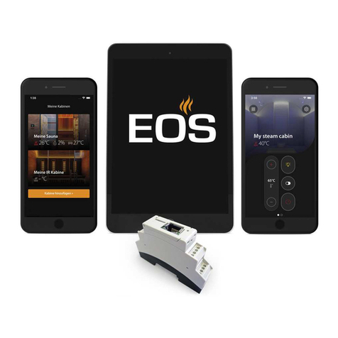
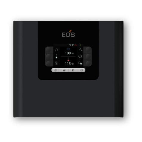
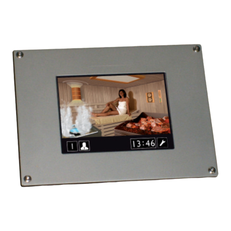
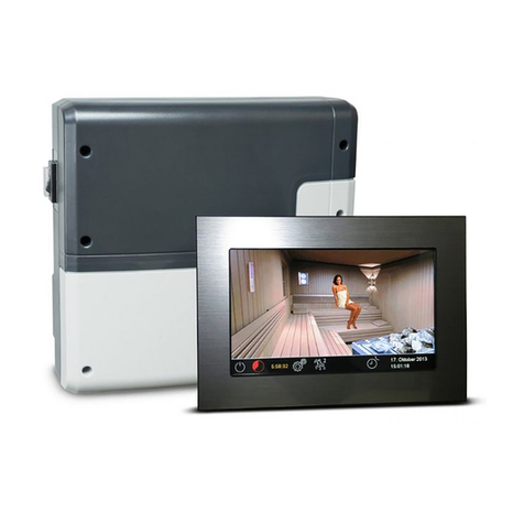
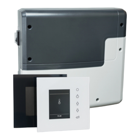
EOS EmoTouch II + User manual

I N N O V A T I V E S A U N A T E C H N O L O G Y
Made in Germany
Control panel is not at 945950
Print no. 29344773 de / 39.16
Technical data subject to change
GB Installation and operating manual
EmoTouch II + Steam
Steam bath control unit

2GB
English
Content
Scope of Delivery ................................................................................................................................................... 4
Accessories ................................................................................................................................................................ 4
Technical data........................................................................................................................................................... 5
General information about the steam bath................................................................................................... 6
General safety regulations................................................................................................................................... 7
Installation ................................................................................................................................................................. 9
Main relay box.............................................................................................................................................9-10
Display panel...................................................................................................................................................11
Temperature sensor......................................................................................................................................14
Electrical connection............................................................................................................................................16
Connection of the steam generator .......................................................................................................16
Connection of the lighting.........................................................................................................................17
Connecting a power extension unit .......................................................................................................17
Heating time limitation ...............................................................................................................................17
Installation diagram and terminal arrangement................................................................................18
Putting into service (initial setup) ...................................................................................................................21
Operation .......................................................................................................................................................... 22-33
Overview...........................................................................................................................................................22
Symbol explanation (start screen)...........................................................................................................23
Description of icons (advanced settings)..............................................................................................24
Graphical user interface / querying the climate readings ..............................................................25
Operation and settings (main functions)....................................................................................... 26-29
Other settings .......................................................................................................................................... 30-33
Service level settings..................................................................................................................................... 34-36
Error messages (troubleshooting)...................................................................................................................37
The device switch (switch-o)..........................................................................................................................38
Recycling ..................................................................................................................................................................39
Service Address:.....................................................................................................................................................39
Guarantee ................................................................................................................................................................39
General Terms and Conditions of Service.....................................................................................................40

3
GB

4GB
Delivery scope
(Subject to change)
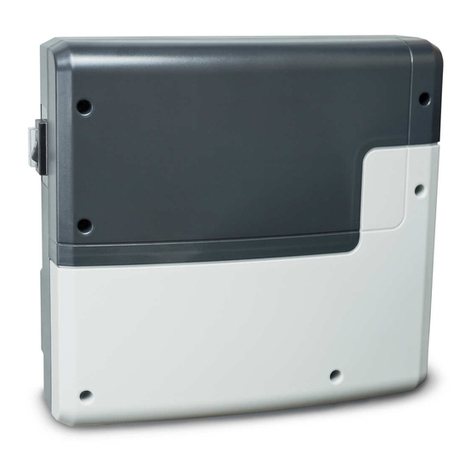
1. Main relay box (2-part front cover), wall-mounted
2. Control panel with 7“ touchscreen display (upper part of housing) -not for 945950-
3. Lower part of housing (for installation of the control panel) -not for 945950-
4. Dismantling tools for control panel (2x) -not for 945950-
5. Temperature sensor with a) cylindrical stainless steel housing Ø15 x 65 mm
and b) pre-mounted connection cable line 5 m, with RJ10 connector
6. Connection cable (control panel to relay box) with RJ14 / RJ10 modular plug -nit for 945950-
7. Plastic bag containing three 4 mm x 20 mm screws
8. 5 wire protection sleeves
9. Installation/operating instructions
Optional accessories and extensions:
Colour light control module....................#94.5996 / 94.6007
Sound module..............................................#94.5921 / 94.5920
Extractor fan..................................................#92001.4402
Disc valve (plastic).......................................#2001.4404
Disc valve (stainless steel) ........................#2001.5210
4
9
78
5b
1
2
3
6
a

5
GB
Technical data
Nominal voltage: 400 V AC, 3 N, 50 Hz
Power output: max. 9 kW resistive load, expandable to 36 kW by connecting power
switchgear
Heating time limitation: 6 hours / 12 hours / no limit (display: --:--:--)
Housing: plastic (contactor box and control panel)
Display: high-resolution 7" touch screen colour display, 16:9
Operation: Via touch screen GUI or symbols.
Temperature control range: 25° - 50°C
Sensor system: Digital sensor in the cylindrical stainless steel housing Ø15 x 65 mm
Control characteristics: digital two-step control, adjustable hysteresis
Fan connection: min. 5 W, max. 150 W (only fans without starting capacitor)
Only use fans suitable for phase lead edge control, otherwise the fan or
the control unit may be damaged!
Connection for cabin light: min. 5 W (20 mA),
Resistive loads - max. 150 W,
Dimmable energy-saving lamps - max. 35 W
Lights on conventional transformers - max. 60 VA.
Note: Only connect dimmable illuminants and transformers!
!
!
!
!
!
!
!
!
!
!
!
!
!
!
!
!
!
!
!
!
!
Fan and light connection share a 5 AT fuse for protection.
Volt-free output: contact's resistive load carrying capacity:
maximum current: 16 A
maximum voltage: 30 V DC / 250VAC
Pre-set timer: up to 24 hours in advance
Recurrent switching timer: weekly timer, 4 times per day or single event timer
Error messages: plain text on the display
Outputs: 3 x RJ10 socket for sensor
2 x RJ14 sockets for control panel and extension modules
1 x volt-free contact (terminals 3 and 4)
Output S1: maximal load 50 W / 50 VA, no capacitive loads allowed.
Terminal block area for power supply and steam generator connection:
0.5 – 2.5 mm² rigid or exible crimped wire, two cores with the same
cross section per terminal may be connected
Terminal block area WM, 3, 4, light, fan:
0.34 – 2.5 mm² rigid or exible crimped wire
Please observe the minimal cross section as per fuse protection of the line!
Card reader: SD card reader in control panel (for SD and SD.HC cards).
Ambient temperature: -10°C to +35°C
Storage temperature: -20°C to +60°C
Relay box dimensions H 270 x W 300 x D 100 mm
Control panel dimensions H 142 x W 210 x D 42 mm (tted version)
installation depth: approx. 35 mm

6GB
Dear customer,
On purchasing this control unit, you have ac-
quired a high-quality device that was develo-
ped and manufactured in compliance with the
latest standards and quality guidelines. Please
note that perfect interaction of the steam
bath cabin, the steam generator and control
unit must be guaranteed to achieve the typi-
cal pleasant steam bath atmosphere in your
cabin. This high-quality control unit is used to
'operate' your steam bath system; its many pro-
gramming options allow you to quickly nd the
settings that best suit your requirements.
Everybody experiences the climate in
the steam bath dierently, which is
why you need to nd your own indivi-
dual settings, or those of your family.
The following operation instructions de-
scribe how to pre-select "your" climate in
the cabin. Read these instructions careful-
ly, so that you can quickly and easily nd
your way though the programming process.
Please note that there are dierent tempera-
tures in the cabin of your steam bath.
Therefore there will always be temperature va-
riations between the control unit temperature
sensor and the thermometer in the cabin.
For instance, a pre-selected temperature of 50
°C may show a value of 38°C on your display
thermometer. This would then also correspond
to the typical climate data in the cabinet.
Only use suitable cabin lights. Always ensure
hygienic conditions.
To prevent draughts inside the cabin, try to
avoid using the fan function during your steam
bath. It should only be used if recommended
by the cabin manufacturer.
General information for steam baths

7
GB
• This device can be used by children aged
8 upwards and by persons with physical,
sensory, or mental disabilities, or persons
who have inadequate experience and
knowledge if they are supervised or if they
have received adequate instruction in how
to use the device safely and understand
the associated risks. Children may not play
with this device. Children may not clean
or carry out any user maintenance if un-
supervised.
• Children should be supervised to ensure
that they do not play with the device.
• Caution: The unit may not be instal-
led in closed switch cabinets or behind
closed wooden panels!
• Only qualied electricians may install the
device.
• You must comply with the regulations of
your electrical supplier and applicable VDE
regulations (DIN VDE 0100).
• Caution, risk of fatal injuries: Ne-
ver carry out repairs or installation work
yourself. Only a qualied technician may
remove the housing cover.
• Please always observe the dimensions
stated in the assembly instructions when
installing the temperature sensor. The
temperature limit values can only be ob-
served if the assembly work is carried out
correctly, and there is a very low tempera-
ture uctuation in the steam cabin.
• The unit may only be used as intended as
a control unit for steam generators up to 9
kW. Control units where there is the opti-
on of increasing the switching capacity in
combination with a power switching unit
can be used up to 36 kW.
• The system must be completely discon-
nected from the mains supply before car-
rying out any installation work or repairs,
i.e. switch o fuses and master switch.
• Observe the safety and installation infor-
mation provided by the manufacturer of
the unit.
• Please also observe the information and
instructions provided by the cabin manuf-
acturer.
General Safety Regulations
8GB
!
!
!
!
!
!
!
!
!
!
!
!
!
!
!
!
!
!
!
!
Caution!
Dear Customer, In compliance with the
current regulations, only a qualied
electrician may connect the electrical
elements of the steam generator or the
steam bath control unit.
We would like to remind you that, in case
of a warranty claim, you will need to pro-
vide a copy of the authorised electronics
company's invoice.

9
GB
Installation of the main electronic unit
1. Take the lower part of the front cover o the relay box. For this undo 3 xation screws, then
pull the cover slightly downwards and take it o. See the g. 1 for details.
The main electronic unit (relay box) may be installed only outside sauna cabin. The recommended
places of installation are the outer sauna wall or a plant room (technical room). The installation
on the sauna roof is also possible. If empty ducts for connection cable are already available, then
they usually predetermine the installation position. The installation shall be carried out as follows:
1.
2.
210
180
3
!
!
!
!
!
!
!
!
!
!
!
!
!
!
!
!
!
!!
Attention: It is forbidden to install the
control box in a closed switch cabinet or
behind a wooden panelling!
Fig. 1
Fig. 2
2. The relay box has three mounting holes on the rear side. Refer to g. 2 below for dimensions
in order to mark the position on the wall (template). The central upper screw shall be used to
hang the relay box onto it with the corresponding opening on its rear side. Two lower screws
shall be used to secure the housing to the wall after it is hanged on the upper screw.

10 GB
180 mm
210 mm
Lower mounting holes
Fig. 3
3. Hang the housing on the central upper screw. Make sure that this screw stands out ap-
prox. 3 mm from the wall surface. If the connection cables shall be connected from the rear,
knock out the corresponding openings in the housing and insert the supplied cable glands
(rubber cable holders) into these openings. Pull the cables through them into the housing.
Secure the housing with two mounting screws 4x25 mm through the corresponding holes as
shown on g. 3 below.
Fig. 4
Knock-out openinigs for connection cables
for heater, vaporizer, fan, lamp.
Knock-out openings
for sensor cables
upper central mounting hole

11
GB
at eye level
188 mm
127 mm
ca. 350 mm
Outer sauna
wall
Insulation
Connection cable
Inner sauna wall
Draw the connection cable from the relay box
to the control panel.
The connection cable may be laid only be-
tween the outer sauna wall and insulation layer
to prevent overheating (Fig. 6).
The insulation should ensure that the temper-
ature at the outer sauna wall may not exceed
75° C.
Pay attention to that the bigger plug (RJ14)
shall be oriented towards the relay box and the
smaller plug RJ10 towards control panel.
Fig. 5
Control panel
Installation place
The control panel may only be mounted out-
side the sauna cabin. If ductwork is already
provided for electrical installations then the
position of the control unit is predetermined
by that. The control panel is designed for
ush-mounted installation into the sauna wall
or a similar adjacent wall. The installation shall
be carried out as follows.
First of all determine the installation position.
Ideally it should be at the eye sight height, as
shown on g. 5
Make a cut-out in the wall with dimensions 127
mm height x 188 mm width.
Be careful not to make it larger than the ange
of the control panel.
Fig. 6
Cable connection
Use the supplied 5 m connection cable with
RJ10 plug (control panel side) and RJ14 plug
(relay box side).
If necessary this connection line may be ex-
tended up to approx. 30 m length. For this you
will need to use a standard coupling RJ14/RJ14
and the extension cable with RJ14 plugs in re-
quired length. The coupling and extension ca-
ble may be purchased from specialist dealers.
Fig. 6.1
RJ14
RJ10
ferrite cylinder
RJ10 jack
rear side of the display panel
pull control unit cable in a loop
through the ferrite cylinder
Note: For the control unit not to be suspended
from the owing steam, the controller attach
opposite the door opening!

12 GB
127
35
188
140
Wandausschnitt
Breite 188 mm
Höhe 127 mm
Tiefe mind. 35 mm
alle Maße in mm
200
4x
4x
4x
4x
4x
Fig. 8
Wall panelling min. 35 mm
First install the housing base into the sauna wall (see g. 8):
1. Loosen 4 screws holding mounting brackets in the base
2. Pull the connection cable through the opening in the housing base.
3. Insert the housing base into the wall cut-out.
4. Adjust the metal brackets to the wall panelling thickness.
5. Tighten the screws - the brackets will be pulled to the wall panelling from inside and will fas-
ten the housing base in the opening.
Wall aperture:
Width 188 mm
Height 127 mm
Depth min. 35 mm
Installation of the housing base
Flush-mounted installation
Fig. 7
cable opening
Notice:
Pay attention to the correct ori-
entation of the housing base, the
opening for connecting cable
should be at the bottom side as
shown on g. 7
all sizes in mm

13
GB
Installation of the upper part (control panel with display)
Place the control panel directly in front of the housing base and pay attention to the correct ori-
entation - the cable connector shall be at the bottom and the SD card slot at the top. Plug in the
connection cable with RJ10 plug which you pulled through the housing base.
Now carefully press the control panel into the housing base until you hear a click sound (hooks of
the upper part should snap into the holders in the base). Make sure the control panel sits reliably
in the base part.
Installation hint: When you lay the connection cable allow some extra length around the base, so
that later you can take the control panel out of the base easily.
Fig. 9
Taking the control panel out
To remove (detach) the control panel use the included de-installation
tools or two slotted screwdrivers. Insert the tools or screwdrivers into the
grooves located on the bottom side (between housing upper part and
housing base) and carefully pull it away from the wall until control panel
is released from the base and may be taken out. Do not apply excessive
force as this may damage the inner holders.
Take the control panel out of the base and detach the connection cable.

14 GB
ca. 160 - 170 cm
15-25 cm
Temperature sensor connection
You should not install sensor and power supply lines together, or lead them through the same
duct. Installing these together may leads to malfunctions in the electronics, e.g. error messages
that the heater sensor cannot be recognised.
Any cable shielding (if any) must be connected to the earth in the control unit.
Please note that the following dimension information are only indications with which the best
climate in the cabin can be reached. Fig. 8-10 give you an overview of the mounting point of the
sensor.
Connect the sensor cable to one of three “sensor bus” RJ10 con-
nectors as shown on page 20 (arrangement of terminals). The tem-
perature sensor may be plugged in any of the three sensor bus
connectors.
The control unit will automatically detect the connected sensor.
Fig. 8
Temperature sensor installation
}
}
}
JP5
Sensor bus
Sauna bus
The temperature sensor should not be installed in the direct proximity of the steam outlet. The
sensor should be mounted either opposite or at a reasonable distance to the steam outlet de-
pending on the steam room size and layout.
A too close installation may cause the steam production to be stopped too early. Too remote in-
stallation in large cabins may cause the sensor react too late to temperature changes which may
create a risk of too high temperatures around the steam outlet.
An optimal position depends on the steam room and may require testing on site.

15
GB
15.Oktober2013
14:22:38
ca. 160 - 170 cm
min. 3 cm
min.
3 cm
Temperature sensor
Sensor cable
Sensor connection RJ10
in the contactor box
Fig. 9
Fig. 10
Temperature sensor - installation overview
Tile
Adhesive
Vapour barrier
ISO panel
Masonry
sealed
with silicone
Notice: If the sensor is mounted with less than
30 mm sticking out of the wall it is likely not to
acquire the air temperature properly. The inu-
ence of the cabin wall temperature has to be
taken into consideration.
The accuracy of temperature control may be
also inuenced by the cabin ventilation (extract
fan duct vent location, ventilation rate).

16 GB
Electrical connections
The electrical connection may only be
carried out by a certied electrician in
compliance with the local legal norms
and applicable guidelines (e.g. VDE).
In general, there may be only one permanent
connection line to the network; therefore
equipment should be provided that makes it
possible to disconnect the system with all poles
from the network with a contact opening width
of minimum 3 mm.
All electrical installations and connection lines
installed inside the cabin must be suitable for
use in steam rooms (IP 65)
Lay the control line(s) from the control panel to
the contactor box and connect them according
to the wiring diagram.
Lay the power supply line to the contactor box
and connect it to the power input terminals
(see wiring diagram).
Mount the steam generator in compliance with
the manufacturer's installation instructions.
Lay the silicone line and connect it to the ap-
propriate terminals as shown in the wiring
diagrams of the control unit and of the steam
generator.
Take heed of the installation diagrams on pag-
es 17 - 19 showing connection examples.
Connection of the steam
generator
Illust. 13
Contactor box, bottom of front cover
open

17
GB
Heating time
LSG
Connecting a power switch-
ing device
Usually, steam generators have a separate
power supply and their own respective power
switching devices (contactors), so that the con-
trol unit will only supply the switching signal.
The control unit may be however used to sup-
ply up to 9 kW power. The switching capacity of
the control unit can be expanded if necessary
by connecting an optional power switching
unit (LSG) to provide the total switching capac-
ity above 9 kW.
Details can be found in the power switchgear
installation instructions.
Setting jumper 5 on the main board (pages 18
- 19) allows you to limit the maximum heating
time to 6 or 12 hours or to unlimited operation.
"Unlimited" means that the unit needs to be
turned o manually. This function is only al-
lowed in monitored commercial systems.
Otherwise, if the steam room is set to "private"
use, the heating time will be automatically lim-
ited to 6 hours.
The jumper setting has rst priority.
The factory default of all control units is "6
hours".
Connection of the cabin
light
!
!
!
!
!
!
!
!
!
!
!
!
!
!
!
!
The lamp must have protection class IPX6
and be resistant to the ambient temperature.
The lamp can be mounted at any point, how-
ever not directly adjacent to the rising ow of
steam emerging from the steam nozzle.
Use dimmable bulbs only. Take heed of the
maximum output! The control unit detects
highly inductive loads and adapts the phase
shift accordingly.
!
!
!
!
!
!
!
!
!
!
!
!
!
!
!
Caution! Use dimmable bulbs and
transformers only! Connecting non-dimma-
ble bulbs or transformers may damage the
bulb or the control unit. This will void the
warranty (guarantee).
Extractor fan connection
Only fans with the phase lead edge
rotation speed control are suitable.
The extractor fan should have at
least IPx6 protection class. The fan should not
be mounted inside the steam cabin.
Recommended position of the duct vent for
air extraction is in the ceiling of the cabin. The
position of the duct vent may have an inu-
ence on the temperature regulation if the fan
is operated during steam production.
Connect the fan as per wiring diagram.

18 GB
!
!
!
!
!
!
!
!
!
!
!
!
!
!
!
!
!
!
WARNING! RISK OF
FATAL INJURIES!
Never carry out repairs or installation
work yourself. Only a qualied technician
may remove the housing cover.
!
!
!
!
!
!
!
!
!
!
!
!
!
!
!
!
ATTENTION!
Connecting a sensor to the sauna bus
(RJ14 socket) may damage the sensor
and the control unit main board!
Installation diagram example EmoTouch II+ Steam
Connect the sensor cable to one of three RJ10
connectors of the sensor bus as shown on page
20 (arrangement of terminals). The tempera-
ture sensor may be plugged in any of the three
sensor bus connectors.
The control unit will automatically detect the
connected sensor.
Installation diagram EmoTouch II+ Steam with Steamtec Classic
Schaltlasterweiterung
LSG, optional
Power extension,
optional
Temperaturfühler
Temperature sensor
P max. 9 kW
Sensorbus
Saunabus
reserviert
L2 + L3 optional, wenn V+W nicht verwendet werden
STB
L1 L2 L3 N W V U N N FL F N LL L N
WB
WM
PE
NL1 L2 L3
Leistungsteil
Main unit (relay box)
Relais box
Силовой блок
potentialfreier
Kontakt
3 4
S1
S1 N
Bedienteil
Control panel
Tableau de commande
Пульт управления
EmoTouch II+
STB
L1 L2 L3 N W V U N NFL F N L L LN
WB
WM
Leistungsteil
Main unit (relay box)
Relais box
Силовой блок
3 4
S1
S1 N
PE
N
L
potentialfr. Kontakt
volt-free contact
L1
L2L3 N PE 27 28 S1
LWB PEN
Steamtec Classic
Emotouch II+ Steam / LSG Steam
X3
400 V 3N
AC 50 Hz
PE

19
GB
Installation diagram example EmoTouch II+ Steam with Steamtec II Basic
1 2 3 4 5 6 7 8 9 10 11 12 13 14 15 16 17
1 2 3 4 5 6 7 8 9 10 11 12 13 14 15 16 17 18 19 20 21 22 23 24
N
S1
Wb
PE
N
S1
Wb
PE
L1
L2
L3
N N N N PE PE
L1
L1
L2
L2 L3 L3 N N N N N N N N PE PE
Steamtec II Basic
9,0 kW
Steamtec II Basic
18,0 kW (Supply 3 x 32 A)
L1
L2
L3 N PE
400 V 3N 50 Hz AC 32 A + PE
L1
L2
L3 N PE
400 V 3N 50 Hz AC
16 A + PE
1 2 3 4 5 6 7 8 9 10 11 12 13 14 15 16 17 18 19 20 21 22 23 24
N
S1
Wb
PE
L1
L4
L2
L5 L3 L6 N N N N N N N N PE PE
Steamtec II Basic
18,0 kW (Supply 6 x 16 A)
L1
L2
L3 N PE
400 V 3N 50 Hz AC 16 A + PE
Temperaturfühler
Temperature sensor
L4 L5 L6
N PE
400 V 3N 50 Hz AC 16 A + PE
3 Brücken entfernen
(1-2/3-4/5-6)
remove 3 bridges
(1-2/3-4/5-6)
25 26 27 28
N
A2
PE
FRAGRANCE
25 26 27 28
N
A2
PE
FRAGRANCE
Sensorbus
Saunabus
reserviert
Bedienteil
Display
STB
PE
N
L
Leistungsteil
Main unit (relay box)
Relais box
Силовой блок
Emotou ch II+ Steam / LSG St eam
PE
230 V AC
Steuerung
Control
L1 L2 L3 N W V U N FL F N L L L N
potentialfreier
Kontakt
3 4
S1
S1 N
Temperaturfühler
Temperature sensor
Sensorbus
Saunabus
reserviert
Bedienteil
Display
STB
PE
N
L
Leistungsteil
Main unit (relay box)
Relais box
Силовой блок
Emotou ch II+ Steam / LSG St eam
PE
230 V AC
Steuerung
Control
L1 L2 L3 N W V U N FL F N L L L N
potentialfreier
Kontakt
3 4
S1
S1 N
Temperaturfühler
Temperature sensor
Sensorbus
Saunabus
reserviert
Bedienteil
Display
STB
PE
N
L
Leistungsteil
Main unit (relay box)
Relais box
Силовой блок
Emotou ch II+ Steam / LSG St eam
PE
230 V AC
Steuerung
Control
L1 L2 L3 N W V U N NFL F N L L L N
WB
WM
potentialfreier
Kontakt
3 4
S1
S1 N
18 19 20 21
N
A2
PE
FRAGRANCE
N
WB
WM
N
WB
WM

20 GB
Terminal arrangement on the main board (relay box)
Temperature
limiter (STB)
}
}
}
I
II
WB
N
STB
fan light
FL
WM
FN LL LN
L1 L2 L3 N W V U N 3 4
S1
S1 N
M A I N S O V E N V A P.
JP5
Neutral
Neutral
Sensor bus
Status LEDs
Sauna bus
reserved
Button for programming the
cabin address (green)
Power extension output
Power supply, phase 1
Power supply, phase 2
Power supply, phase 3
Heater output, phase 1
Heater output, phase 2
Heater output, phase 3
Fan output / phase
Fan output / neutral
Light output, phase
Light output, neutral
Floating contact, 16 A
Programming the cabin address
1. Press button >4s – to start the program-
ming mode; the red light ashes approx.
150ms on, 500ms o
2. Press button briefly (> 0.5s) – the green LED
shows the set address via the number of
flashes; the switching times: approx. 400ms
on, 400ms off
3. The next address is selected every time the
button is pressed.
4. As the control unit is usually supplied with
address 1, pressing the button for the first
time after starting the programming mode
sets the address 2; the green LED flashes
twice.
5. Address 1 follows address 8
6. the programming mode is automatically
quit if no button is pressed form more than
10s. The new address is thereby perma-
nently saved.
Commissioning:
Steam expansion kit Art. No.: 945950
The maximum temperature in a steam bath
cabin may not exceed 50°C. If, on the basis of
its output, the steam generator is capable, the
maximum temperature needs to be reduced
manually, if the software status of the control
panel is older than V3.07. To do this, touch the
settings symbol for more than 5s and en-
ter the following code 3715 as requested. The
maximum settable temperature can now be
reduced to 50°C in the following menu. After
quitting the setting menu, check that the set
maximum temperature is now 50°C.
Jumper 5
6 h
12 h
∞
Adress 1 = Sauna
Adress 2 = Steam bath
Jumper liegen dem Gerät
bei / sind blind gesteckt
Other manuals for EmoTouch II +
2
Table of contents
Other EOS Control Unit manuals
Popular Control Unit manuals by other brands

mikroElektronika
mikroElektronika click BOARD IR reflect click manual

GEM
GEM 563 Installation, Operating and Maintenance Instructions for the Installer and the User

Gifas-electric
Gifas-electric TrafficLED installation instructions

CALEFFI
CALEFFI 200000 manual

Keba
Keba KeDrive D3-DU 3 A Series Project engineering manual

Viessmann
Viessmann VITOSOLIC 100 operating instructions