Diodes AL8843EV1 User manual
AL8843EV1 User Guide
AL8843EV1 Page 1 of 10
Dec 2017
www.diodes.com
General Description
The AL8843 is a hysteresis mode DC-DC
step-down converter, designed for driving
single or multiple series connected LEDs
efficiently from a voltage source higher
than the LED voltage. The device can
operate from an input supply between 4.5V
and 40V and provide an externally
adjustable output current up to 3A.
Depending upon supply voltage and
external components, this converter can
provide up to 60W of output power.
The AL8843 integrates the power switch
and a high-side output current sensing
circuit, which uses an external resistor to
set the nominal average output current.
Dimming can be realized by applying an
external control signal to the CTRL Pin. The
CTRL Pin will accept either a DC voltage
signal or a PWM signal.
The soft-start time can be adjusted by an
external capacitor from the CTRL Pin to
Ground. Applying a voltage of 0.3V or lower
to the CTRL Pin will shut down the power
switch.
Applications
LED Retrofit for Low Voltage Halogen
Low Voltage Industrial Lighting
LED Backlighting
Illuminated Signs
External Driver with Multiple Channels
Key Features
Wide Input Voltage Range: 4.5V to 40V
Output Current up to 3A
Internal 40V NDMOS Switch
Typical 4% Output Current Accuracy
Single Pin for On/Off and Brightness
Control by DC Voltage or PWM Signal
Recommended Analog Dimming Range:
10% to 100%
Soft-Start
High Efficiency (Up to 97%)
LED Short Protection
Inherent Open-Circuit LED Protection
Over Temperature Protection (OTP)
Up to 1MHz Switching Frequency
SO-8EP Packages Available in Green
Molding Compound (No Br, Sb)
AL8843EV1 Specifications
Parameter
Value
Input Voltage
5VDC to 40VDC
LED Current
2A
Number of LEDs
1~10 LEDs
XYZ Dimension
63mm x 40mm x 10mm

AL8843EV1 User Guide
AL8843EV1 Page 2 of 10
Dec 2017
www.diodes.com
Figure 1: Top View
Figure 2: Bottom View
Connection Instructions
Power Supply Input: 5~40VDC (VIN, GND)
CTRL: Internal voltage ref. pin (2.5V). This pin can be used to achieve dimming and for switching
the output current off. Leave floating for normal operation.
PWM Signal Input: Remove C4, apply PWM signal to CTRL (CTRL, GND)
Analog Signal Input: Connect 470nF capacitor to C4, apply analog signal to CTRL (CTRL, GND)
LED A: LED A connects to the external LED anode
LED K: LED K connects to the external LED cathode
AL8843EV1 User Guide
AL8843EV1 Page 3 of 10
Dec 2017
www.diodes.com
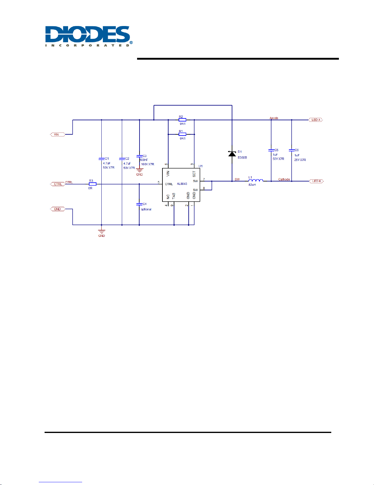
Evaluation Board Schematic
Figure 3: Evaluation Board Schematic
AL8843EV1 User Guide
AL8843EV1 Page 4 of 10
Dec 2017
www.diodes.com
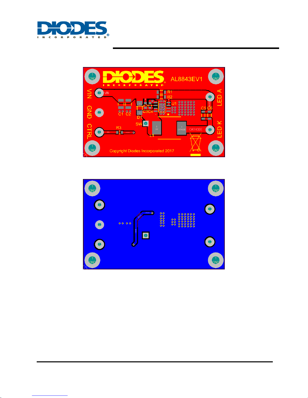
Evaluation Board Layout
Figure 4: PCB Board Layout Top View
Figure 5: PCB Board Layout Bottom View
Quick Start Guide
1. By default, the evaluation board is preset at 2A LED Current by R1 and R2.
2. Non-dimming operation: Leave CTRL pin floating for normal operation.
3. Power Supply: Connect the 5~40VDC to VIN & GND pin to supply the system and AL8843.
4. PWM Dimming: Remove C4; apply a PWM signal (low level < 0.3V and high level > 2.5) to
CTRL pin to dim the LEDs. The recommended PWM signal frequency is from 100Hz to 1kHz,
and the PWM duty is from 1% to 100%.
5. Analog Dimming: Connect 470nF capacitor to C4; the CTRL pin may be driven between 0.4V
and 2.5V adjusting the output current from 10% to 100% of ILED.

AL8843EV1 User Guide
AL8843EV1 Page 5 of 10
Dec 2017
www.diodes.com
Bill of Material
Ref
Value
Package
Part Number
Manufacturer
Notes
U1
AL8843
SO-8EP
AL8843SP-13
Diodes
DC-DC converter
D1
60V, 3A
SMB
B360B-13-F
Diodes
Schottky diode
R1, R2
0R100
1206
Generic
+/-1%
R3
0R
0805
Generic
+/-5%
C1, C2
4.7uF, 50V
1210
C1210X475K5RAC
Generic KEMET
X7R
C3
100nF,100V
0805
Generic
NMC0805X7R104K100
NIC
Components
X7R
C4
Not Fitted
0805
Optional soft start
capacitor
C5, C6
1uF, 100V
1206
Generic
NMC1206X7R105K100
NIC
Components
X7R
L1
82uH
1280
744770182
Würth Elektronik
82uH, ~0.16R, ~2.45A
Note: The component part numbers are correct at the time of publication. Diodes Inc reserves the right to
substitute other parts where necessary, without further notification.
Table of contents
Other Diodes Media Converter manuals


Popular Media Converter manuals by other brands


H&B
H&B TX-100 Installation and instruction manual

Bolin Technology
Bolin Technology D Series user manual

IFM Electronic
IFM Electronic Efector 400 RN30 Series Device manual

GRASS VALLEY
GRASS VALLEY KUDOSPRO ULC2000 user manual

Linear Technology
Linear Technology DC1523A Demo Manual

Lika
Lika ROTAPULS I28 Series quick start guide

Weidmuller
Weidmuller IE-MC-VL Series Hardware installation guide

Optical Systems Design
Optical Systems Design OSD2139 Series Operator's manual

Tema Telecomunicazioni
Tema Telecomunicazioni AD615/S product manual

KTI Networks
KTI Networks KGC-352 Series installation guide

Gira
Gira 0588 Series operating instructions

Lika
Lika SFA-5000-FD user guide