Diodes AP63201 User manual

AP63201
EVB User Guide
This EVB User Guide contains new product information. Diodes, Inc. reserves the right to modify the product specification without
notice.
No liability is assumed as a result of the use of this product. No rights under any patent accompany the sale of the product.
1 of 6
www.diodes.com
June 2019
© Diodes Incorporated
AP63201 EVB User Guide
AE Department
1. General Description
The AP63201 is a 2A, synchronous buck converter with up to 32V wide input voltage range, which fully
integrates a 140mΩ high-side MOSFET and a 70mΩ low-side MOSFET to provide high efficiency
step-down DC/DC conversion. The AP63201 adopts peak current mode control with the integrated
compensation network, which makes AP63201 easily to be used by minimizing the off-chip component
count..
The AP63201 is an Electromagnetic Interference (EMI) friendly buck converter with implementing
optimized design for EMI reduction. The AP63201 features Frequency Spread Spectrum (FSS) with ±6%
jittering span of the 500 kHz switching frequency and modulation rate 1/512 of switching frequency to
reduce the conducted EMI. The converter has proprietary designed gate driver scheme to resist switching
node ringing without sacrificing MOSFET turn on and turn off time, which further erases high frequency
radiation EMI noise caused by the MOSFETs hard switching.
The AP63201 offers output overvoltage protection, cycle-by-cycle peak current limit, and thermal
shutdown protection. The device is available in a low-profile TSOT23-6 package.
2. Applications
White Goods, Home Appliance
Surveillance
Audio, WiFi Speaker
Printer
DTV, STB, Monitor/LCD Display
Charging Station
AP63201
EVB User Guide
This EVB User Guide contains new product information. Diodes, Inc. reserves the right to modify the product specification without
notice.
No liability is assumed as a result of the use of this product. No rights under any patent accompany the sale of the product.
2 of 6
www.diodes.com
June 2019
© Diodes Incorporated
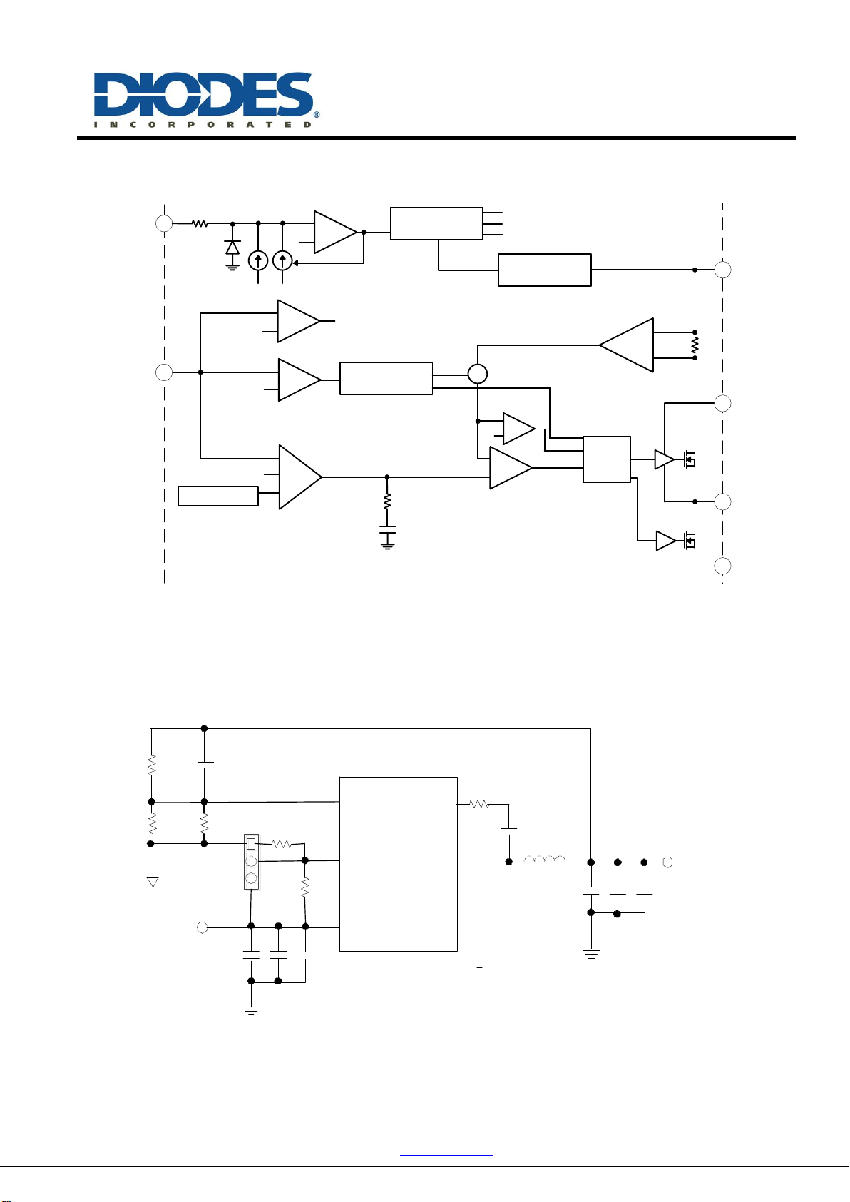
3. Function Block
0.4V
0.8V
1.1V
+
-
+
-
+
-
-
+
0.88V
0.6V
+
0.8V
Internal SS
Error
Amplifier
OVP
PWM
Comparator
Oscillator
500kHz +
Logic
-
+
Ref OCP
7.6nF
18k
SE= 0.9V/T
RT= 0.xxV/A
UVP
HS
LS
1
2
EN
FB
4GND
5SW
6BST
3VIN
gm
20k +
-
Internal
Reference
VCC
Regulator
ON
1.18V
1.5uA 4uA
COMP
4. AP63201 EV Board Schematic
R3
VIN
BS
LX
FB
L1
C1~3
GND
C6~8
VOUT
AP63201
C4
C5
EN
R1
VIN
R2
R5
R6
R4
H
EN
L
AP63201
EVB User Guide
This EVB User Guide contains new product information. Diodes, Inc. reserves the right to modify the product specification without
notice.
No liability is assumed as a result of the use of this product. No rights under any patent accompany the sale of the product.
3 of 6
www.diodes.com
June 2019
© Diodes Incorporated
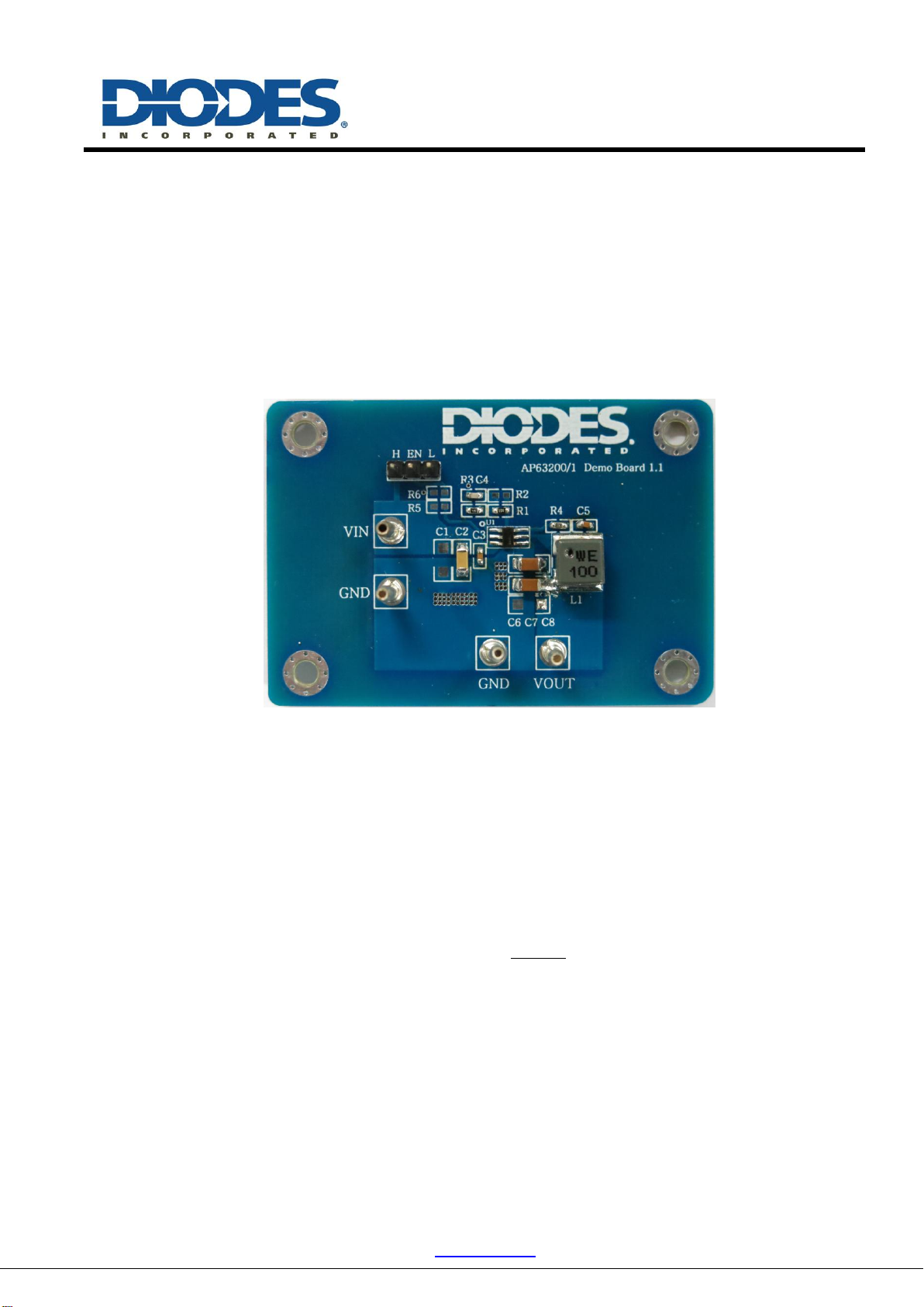
5. AP63201 EV Board Description
The EV board is suitable evaluation board for the AP63201, a DC/DC converter. The board is targeted to
be used in providing a simple and convenient evaluation environment for the AP63201. Requires parts,
power supply connectors etc. on the board, which makes it easy to be evaluated.
6. AP63201 EV Board View
7. Setting the Output Voltage of AP63201
(1) Setting the output voltage
The AP63201 features external programmable output voltage by using a resistor divider network R3 and R1
as shown in the typical application circuit. The output voltage is calculated as below,
1
31
8.0 RRR
VOUT
First, select a value for R1 according to the value recommended in the table 1. Then, R3 is determined. The
output voltage is given by Table 1 for reference. For accurate output voltage, 1% tolerance is required.
(2) Output feed-forward capacitor selection
The AP63201 has the internal integrated loop compensation as shown in the function block diagram. The
compensation network includes an 18k resistor and a 7.6nF capacitor. Usually, the type II compensation
AP63201
EVB User Guide
This EVB User Guide contains new product information. Diodes, Inc. reserves the right to modify the product specification without
notice.
No liability is assumed as a result of the use of this product. No rights under any patent accompany the sale of the product.
4 of 6
www.diodes.com
June 2019
© Diodes Incorporated
network has a phase margin between 60 and 90 degree. However, if the output capacitor has ultra-low ESR,
the converter results in low phase margin. To increase the converter phase margin, a feed-forward cap C4 is
used to boost the phase margin at the converter cross-over frequency,
C
f
. The feed-forward capacitor is
given by Table 1 for reference. The feed-forward capacitor is calculated as below,
3
42
1
R
CfC
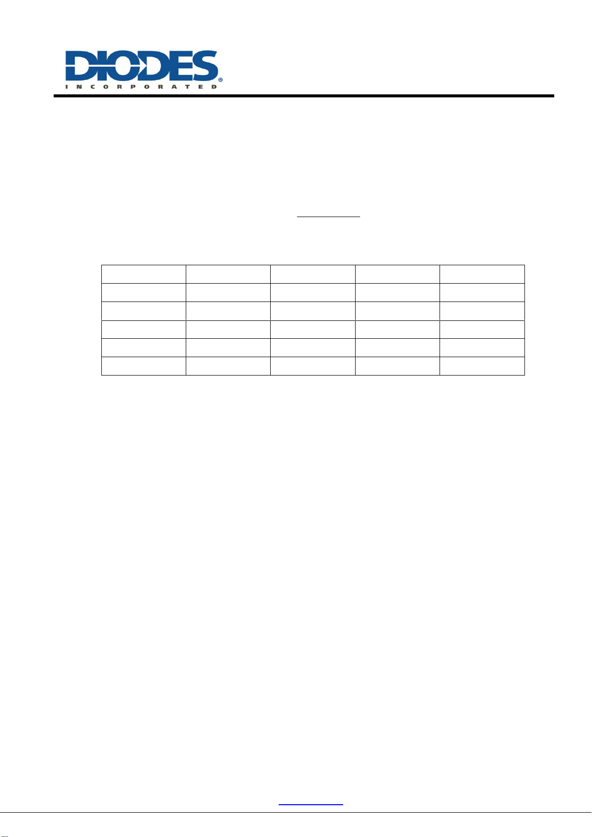
Table 1. Resistor selection for output voltage setting
Vo
R3
R1
C4
C6-C8
1.8V
77.5 KΩ
62 KΩ
100pF
22uFx2
2.5V
131 KΩ
62 KΩ
100pF
22uFx2
3.3V
182 KΩ
62 KΩ
100 pF
22uFx2
5V
157 KΩ
30 KΩ
100 pF
22uFx2
12V
249 KΩ
18 KΩ
56 pF
22uFx4
8. External Components Selection
1) Input & output Capacitors (Cin, Cout)
(1) For lower output ripple, low ESR is required.
(2) Low leakage current needed, X5R/X7R ceramic recommend, multiple capacitor parallel
connection.
(3) The Cin capacitances are greater than 10uF.
(4) 44μF ceramic output capacitors recommended work for most applications, ue to a capacitor’s
de-rating under DC bias, The 88uF is recommend for high output voltage condition. the output
capacitor choose is shown on table1.
2) Bootstrap Voltage Regulator
(1)An external 0.1uF ceramic capacitor is required as bootstrap capacitor between BST and SW pin to
work as high side power MOSFET gate driver.
3) Inductor (L)
(1) Low DCR for good efficiency
(2) Inductance saturate current must higher than the output current
(3) The recommended inductance is shown in the table 2 below.
AP63201
EVB User Guide
This EVB User Guide contains new product information. Diodes, Inc. reserves the right to modify the product specification without
notice.
No liability is assumed as a result of the use of this product. No rights under any patent accompany the sale of the product.
5 of 6
www.diodes.com
June 2019
© Diodes Incorporated
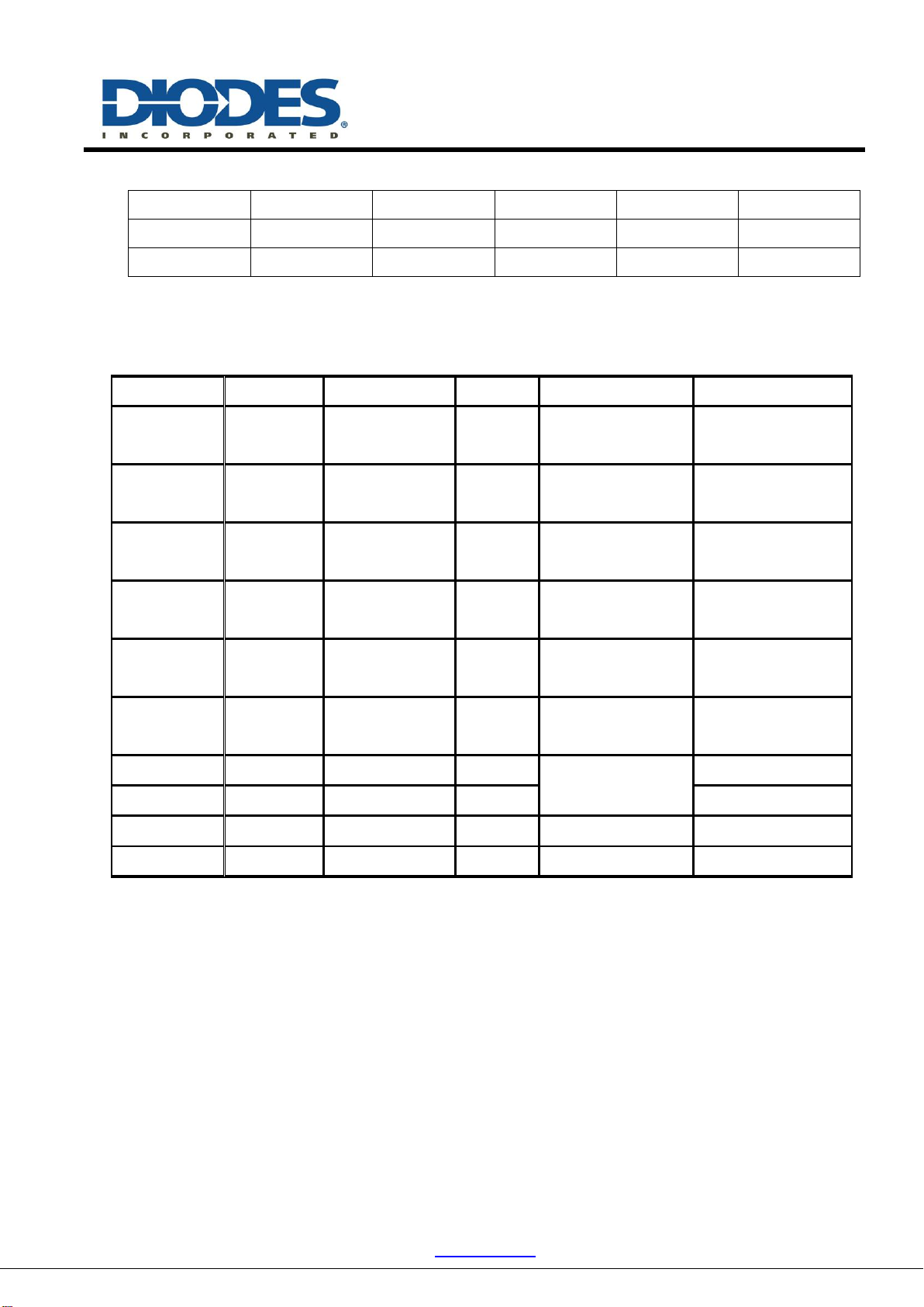
Table 2. Recommended inductors
Output Voltage
1.8V
2.5 V
3.3 V
5.0 V
12 V
Inductor
3.3 uH
3.3 uH
6.8 uH
10 uH
15 uH
Würth PART
744 393 440 33
744 393 440 33
744 393 460 68
744 393 461 00
744 393 461 50
9. EV Board BOM List for AP63201
Item
Value
Type
Rating
Description
Description
C2
10uF
X5R/X7R,
Ceramic/1206
35V
Input CAP
C3
0.1uF
X5R/X7R,
Ceramic/0603
50V
Input CAP
Würth PART
885 012 206 095
C4
100pF
0603
100V
Feedback CAP
Würth PART
885 012 206 102
C5
0.1uF
X5R/X7R,
Ceramic/0603
50V
Bootstrap CAP
Würth PART
885 012 206 095
C6 & C7
22uF
X5R/X7R,
Ceramic/1206
25V
Output CAP
L1
10uH
6060
5.0A
Inductor
Würth PART
744 393 461 00
R1
30K
0603
1%
Voltage set RES*
R3
157K
0603
1%
R4
0
0603
1%
Bootstrap RES
U1
AP63201
TSOT23-6
Diodes BCD
*Note: The present value of R3/R1 are based on Vout=5.0V
AP63201
EVB User Guide
This EVB User Guide contains new product information. Diodes, Inc. reserves the right to modify the product specification without
notice.
No liability is assumed as a result of the use of this product. No rights under any patent accompany the sale of the product.
6 of 6
www.diodes.com
June 2019
© Diodes Incorporated
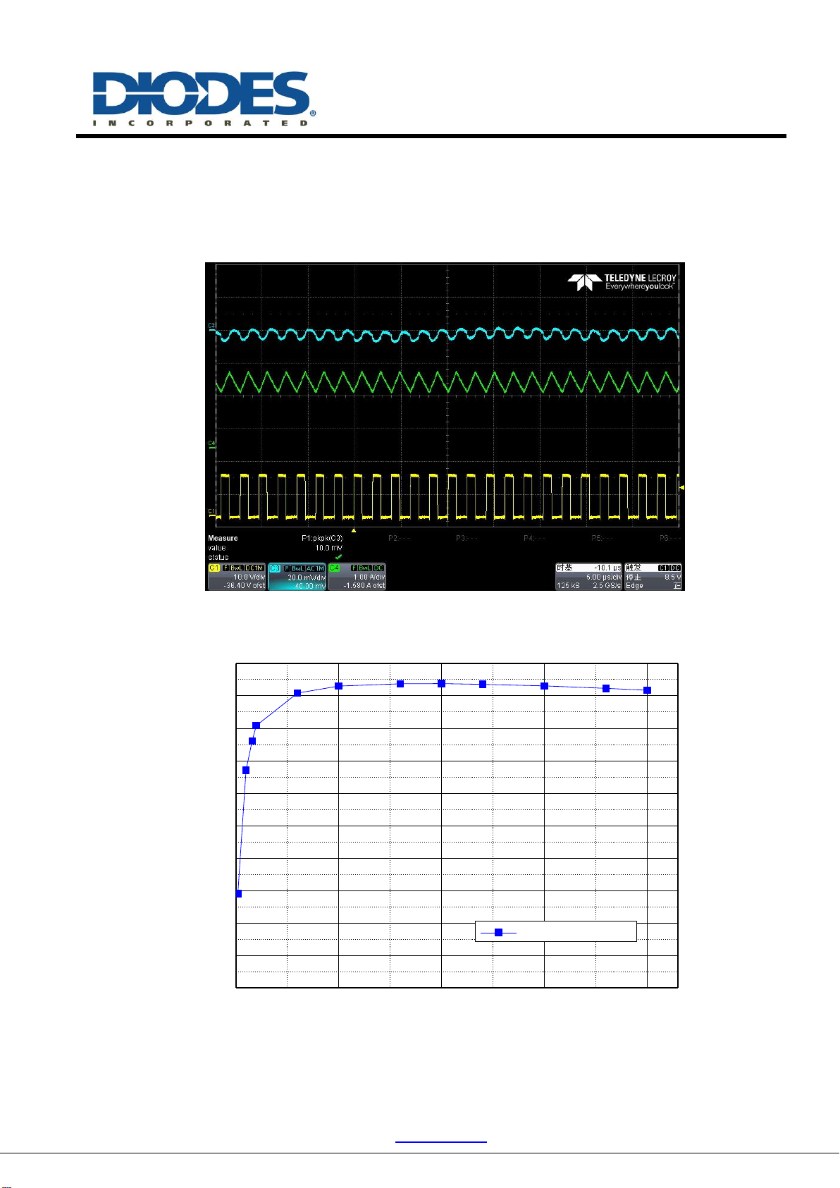
10. Test Waveforms
Test condition: Vin=12V Vo=5.0V Io=2.0A
(Blue: Vout-AC; Yellow: Vsw; Green: IL)
500 1000 1500 2000
0
10
20
30
40
50
60
70
80
90
100
Efficiency(%)
Input Current(mA)
Vin=12V Vo=5V
Table of contents
Other Diodes Media Converter manuals


