diodor DIO-FL200W-WM Manual

DIODOR LED POWERHOUSE
Diodor Pro 120W / 200W LED Floodlights
Models:DIO-FL120W-WM & DIO-FL200W-WM
Installation & operating instructions

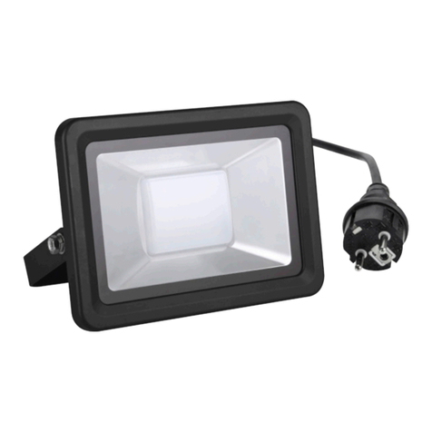
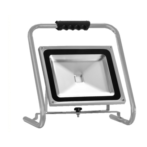
TheDIODOR LED Powerhouse floodlighta high-powered, professional LED floodlight whichis suitable for use outdoors in a
rangeofcommercialapplicationsincludinglightingperimeters,carparks,gardenareasandoutsidewarehousefacilities.
Theunitrequiresconnectiontoa230AC50Hzmainselectricitysupply.
WARNING: THIS PRODUCT MUST BE INSTALLED BY A QUALIFIED ELECTRICIAN, AND CHECKED TO ENSURE
IT IS SAFE, BEFOREUSING.
PLEASE FOLLOW THESE INSTRUCTIONS CAREFULLY BEFORE ATTEMPTING TO INSTALL ANDOPERATE
THIS LIGHT.
Theriskofelectricshockshouldbeminimizedbytheinstallationofappropriatesafetydevicesincludingtheincorporation
ofanRCCB(ResidualCurrentCircuitBreaker)intothemaindistributionboard.
DONOTwirethisfloodlightinto thelightingcircuit.Useaswitched fusedspur.Cablesshouldalwaysbeprotectedagainst
shortcircuitandoverloadbyuseof anRCD.
Ensurethevoltagemarkedontheproductis thesameas theelectricalpowersupplytobe used.
DONOTinstallthelightindooror whereit islikelytobeknockedorhit;inhotorhumidconditionssuchasnearanexhaust
outlete.g.boilerflue,dryeroutlet.
DONOTpositionthelightnearflammableorcombustiblematerials(suchaswood,cloth,paper)or nearflammable,
combustibleorexplosiveliquids,solids,gasesorequipment.
DONOTdirectthelightintoaperson’seyes.Thislighthas averyintensivelightoutput,whichif incorrectlyusedcould
cause eyedamage.
ALWAYSdisconnectthemainspowersupplybeforeservicingorperforminganymaintenance.
ALWAYSmaintainthelightingoodcondition,withrepairsonlyundertakenbya qualifiedelectrician.
ONLYcarryoutrepairsusinggenuineparts.Non-authorizedpartsmaybe dangerousandwillinvalidatethewarranty.
Diodor LED Powerhouse – INSTALLATION AND OPERATING INSTRUCTIONS
1. IMPORTANT SAFETY INSTRUCTIONS
1.1. IMPORTANT INSTALLATION INSTRUCTIONS
1.2. IMPORTANT OPERATION
& MAINTENANCE INSTRUCTIONS
INCLUDED REQUIRED
1
LED s
o
1
2 M3 10
2 M8 12
2 M8 12
6 M8 10
2 M3
4 6mm
4 1
1 35.5cm
1
125m
m
320m
m
125mm

•
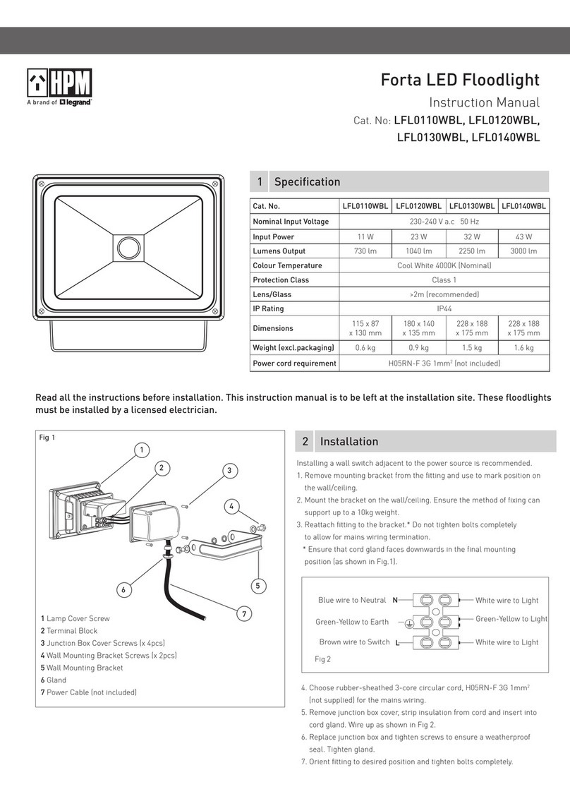
Theunit requires connectionto a 230 AC 50Hz mainselectricity supply.
•
Itis recommended thatthe unitis connectedtothelighting circuit viaa 5 ampfusedspurandusing Twin& Earth 2-Core
roundflexiblecable of at least 1mm
2
gauge(waterproof cable shouldbe used for outdoor installations).
•
It is also advisable to installa single pole wall switch to alloweasycontrol of the floodlight [Fig. 1].
WARNING: Isolate the power supply beforeinstallation.
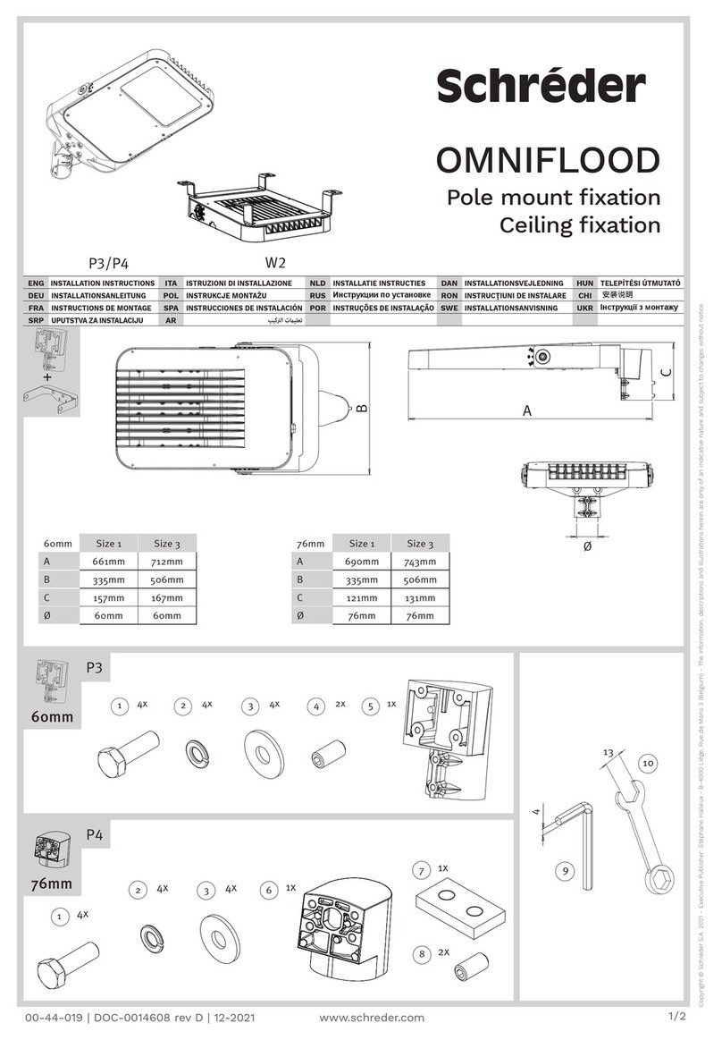
The
Diodor LED Powerhouse
canbefixedinpositionbyEITHER:
Option 1: Attachingthe U bracket to the mounting surface and attaching the Powerhouse to the U bracket, or Option
2: Clampingthepipe bracket to the U bracket around a pipe or pole, and then attaching the Powerhouse.
If attaching the Powerhouse directto a wall usingthe U bracket:
•
Select a mountingpoint which is strong enough to support the weight of the Powerhouse.
•
Attachthe Powerhouse to theU bracket using the two securingbolts provided [Fig.2].
•
PositiontheunitagainstthemountingsurfaceandmarkthepositionfortheUbracket,ensuringthewirescaneasily
reach the unit.
•
UsetheU bracket FixingHoles [Fig.3] to markthe 4drillholesrequired tosecuretheU bracket tothe wall (andmark the
cable outlet location ifrequired).
•
DetachthePowerhouse from theU bracket, drill thewall and screw U bracketonto the wall usingappropriate fixings
which are able support the weight of thePowerhouse.
•
Once the U bracketis securely attachedto thewall, offer the Powerhouse up to theU bracketandsecure using the
securing bolts, spring washers and washers provided[Fig.2].
•
Loosen the 4 screwsholdingthe front of the connection box in placeand remove.
•
Feed the wirethroughthe cableglandon theconnectionbox gentlytighteningglandnutup againstthe glandbody
[Fig. 4] to ensure the wire(s)is secured in placeand no watercan get though into the connection box.
•
Wire the Powerhouse as described in Section4.
2. WIRING REQUIREMENTS
3. FIXING
THE Diodor LED Powerhouse
3.1. OPTION
1: ATTACHING THE Diodor LED Powerhouse VIA THE U BRACKE
T

If attachingthePowerhouse to a pipeor postusing the pipe bracket, first ensurethe pole isstrong enoughto support the
weight ofthePowerhousethen proceedas follows:
•
Establish the correct position for the MightylitePro on the pipe ensuring the wirescaneasily reachthe unit.
•
Positionthepipe bracketandU bracketaroundthepipeand secureusingappropriatenuts boltsand washers(included),
as shown in[Fig.5].
•
OfferthePowerhouseup to the U bracketandsecureusingthe securing bolts, springwashersand washers
provided [Fig.2].
•
Loosen the 4 screwsholdingthe front of the connection box in place, and remove.
•
Feedthewirethroughthecablegland,gentlytighteningglandnutupagainsttheglandbody[Fig.4]to ensurethe
wire(s)is secured in placeand no water can get though into the connection box.
•
Wire the Powerhouse as described in Section4.
•
Oncethepowercablehasbeenfedthroughthecable gland,approximately6mmof insulationshouldbestripped
from each of the coresof AC cablereadyto attachit to theterminalblock in the front of the lightfitting.
NOTE: The Diodor LED Powerhouse DIO-FL120W-WM and DIO-FL200W-WM areClass1 fittings and therefore needto be
Earthed
4.1 CONNECTING TO POWERSUPPLY
IMPORTANT:DiodorLEDPowerhouse hastwodualchanneldriverswhichcontrolthe4LEDarrays withintheMightylitePro.
ThefourBROWN(Live)wiresinthePowerhouseterminal,eachoperateas theLiveforeachoftheLEDarrays,enablingthe
arraystobe wiredto beswitched onandoffindependentlyofeachother(SeeSection4.2WiringOptions).ThetwoBLUE
(Neutral)wiresintheterminaloperateastheNeutralforeachofthedrivers.
Theunitis suppliedwithall4wireslinkedinto2 terminalswhichare,in turn,connectedby asingleBROWNwire.Towirethe
unitsoall4LEDarraysoperatetogetherfromasingleswitch(SingleLevelwiring)proceedasfollows:
•
ConnecttheBROWNorRED(Live)wiretoeitherterminal(marked“L”)holding2BROWNwiresinthefloodlightunit,
and linked together by a singleBROWN wire[Fig.6].
•
ConnecttheBLUEor BLACK(Neutral)wiretotheterminal(marked“N”)holdingthe2BLUEwiresinthefloodlightunit
[Fig.6].
•
ConnecttheYELLOW/GREENorBARE(Earth)wiretotheterminal(marked“EARTH”)holdingtheYELLOW/GREEN
wire in the floodlightunit
Note:OneswitchoperatesthePowerhouse whichis always
atfullpower(100%lightlevel)whenswitchedon. Note: One switch operates two of the Powerhouse LED arrays,
and another controls the other two arrays, enabling the unit to
operate at 50% or 100%power dependenton switching.
3.2. OPTION
2: ATTACHING THE Diodor LED Powerhouse VIA THE PIPE BRACKE
T
4. WIRING THE
FLOODLIGHT
4.2
WIRING OPTIONS
7
Live
Neutral

Note:AseparateswitchisusedtocontroleachofthefourLEDarrayswithinoneor more
Powerhouse
units. Diagram
shows 2 units wiredtogetherso thatboth can operateat 25%, 50%, 75% or 100% light leveldependentupon switching.
•
Aftertheconnectionshavebeensecured,thefloodlightfront(ConnectionBoxfront)shouldbefastenedtothe
ConnectionBox usingthe 4 ConnectionBoxScrews.
•
Oncescrewsare secure,thescrew coversshould be fitted [Fig.10]
•
Tosecuretheangleoflightof the
Powerhouse
setthedesiredposition,tightenthe2 Securingboltsthenusethe 2 x
Allen screws and washers to lock the positionof the
Powerhouse
on theU bracket [Fig.11].
5. AFTER CONNECTING POWER SUPPLY
9: 2
NEUTR
NEUTR
Fig. 10 Fig. 11

Ref:
D
IO
-
FL120W
-
WM
DIO
-
FL200W
-
WM
Description:
DIODOR Powerhouse120W Floodlight DIODOR Powerhouse 200W Floodlight
Fascia:
Matt black polycarbonate
Matt black polycarbonate
Backplate:
Matt black aluminium
Matt black aluminium
ens:
Frosted
Frosted
Wattage:
120W
200W
umens generated:
12000
17000
Voltage:
80 -280V
80 -280V
ED array:
96 EDs
168 EDs
Power factor:
>0.9
>0.9
Efficiency:
<80%
<80%
Colour temperature:
ANSI 5700K
ANSI 5700K
Max. ED life
50,000 hrs
50,000 hrs
Operating temperature:
-40°C to +60°C
-40°C to +60°C
Fixed using mounting bracket: Yes
Yes
Optional pipe bracket:
Yes
Yes
Dimensions (mm):
220(H) x 325(W) x 125(D)
220(H) x 325(W) x 125(D)
Weight (kg):
5.0
5.0
Warranty:
3 years
3 years
6. TECHNICAL SPECIFICATION
This manual suits for next models
1
Table of contents
