MacDon 1000 Programming manual

1

2
INTRODUCTION
Your new bale carrier is designed to retrieve and transport a wide range of round bales.
Sizes that can be accommodated range from 4’ (1.2 m) diameter to 6’ (1.8 m) diameter ina variety
of hay crops as well as small grain and flax straw.
This manual contains useful information regarding operation, safety, and maintenance.
Keep this manual handy for reference and to pass on to new operators or owners.
Call your bale carrier dealer if you need assistance, information,oradditional copies of themanual.
NOTE: Right and Left designations are determined from the operator's position, facing forward.
TAMDEM AXLE
STANDARD
BALE LIFT ARM
PUSHER
ROLL BAR
BALE FORKS

3
TABLE OF CONTENTS
INTRODUCTION ..........................................................................................................................1
TABLE OF CONTENTS................................................................................................................3
SAFETY........................................................................................................................................5
SAFETY ALERT SYMBOL................................................................................................5
SIGNAL WORDS ..............................................................................................................5
SAFETY SIGNS................................................................................................................6
GENERAL SAFETY..........................................................................................................7
SPECIFICATIONS........................................................................................................................9
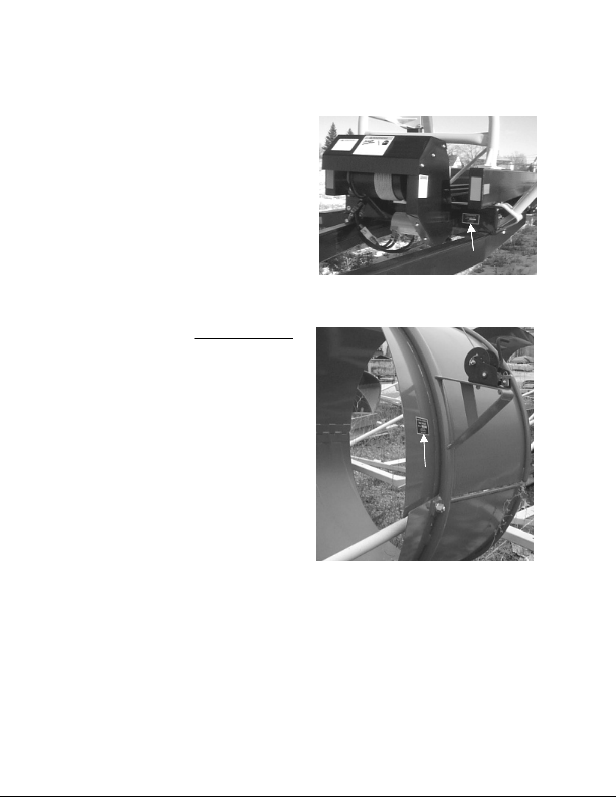
SERIAL NUMBER LOCATION ...................................................................................................10
ASSEMBLY INSTRUCTIONS.....................................................................................................11
LOADING ARM ASSEMBLY...........................................................................................13
OPERATION...............................................................................................................................17
YOUR RESPONSIBILITIES AS AN OWNER/OPERATOR ............................................17
TO THE NEW OPERATOR.............................................................................................18
HYDRAULIC/ELECTRICAL CONTROL..........................................................................18
ATTACHING BALE CARRIER TO TRACTOR................................................................19
ADJUSTING RIGHT WHEELS........................................................................................20
CABLE TENSION............................................................................................................20
CHAIN TENSION............................................................................................................20
CARRIER OPERATION..............................................................................................................22
CARRIER CONTROLS...................................................................................................22
PRE-START CHECKLIST...............................................................................................22
LOADING BALES............................................................................................................23
BALE PUSHER OPERATION.........................................................................................25
UNLOADING...................................................................................................................25
TRANSPORTING CARRIER...........................................................................................27
MAINTENANCE..........................................................................................................................28
FASTENERS...................................................................................................................28
HYDRAULIC SYSTEM....................................................................................................29
CHAIN/SPROCKETS......................................................................................................29
WHEELS/TIRES .............................................................................................................31
LUBRICATION................................................................................................................31
CABLE ............................................................................................................................32
STORAGE ..................................................................................................................................35
END OF SEASON...........................................................................................................35
START OF SEASON.......................................................................................................35
DURING THE SEASON..................................................................................................36
BALE STORAGE.............................................................................................................36

4
SILAGE BAGGER (OPTIONAL).................................................................................................37
OVERVIEW.....................................................................................................................37
INSTALLATION...............................................................................................................38
SETTING YOUR BALER.................................................................................................40
OPERATION...................................................................................................................40
APPENDIX – TIPS FOR SUCCESSFUL SILAGE ..........................................................42
PARTS...................................................................................................................................43-59
TANDEM AXLE...............................................................................................................43
FRAME............................................................................................................................45
CARRIER........................................................................................................................47
DRIVE ASSEMBLY.........................................................................................................49
PUSHER ASSEMBLY.....................................................................................................51
HYDRAULIC/ELECTRICAL ............................................................................................53
DECALS..........................................................................................................................55
RPU.................................................................................................................................57
RPU HYDRAULICS.........................................................................................................59
SILAGE BAGGER (OPTIONAL) .....................................................................................61
SCHEMATICS ............................................................................................................................63
INDEX.........................................................................................................................................64

5
SAFETY
SAFETY ALERT SYMBOL
This safety alert symbol indicates important safety messages in this
manual and on safety signs on the bale carrier.
This symbol means:
ATTENTION !
BECOME ALERT !
YOUR SAFETY IS INVOLVED !
Carefully read and follow the safety message accompanying this symbol.
Why is SAFETY important to you? THREE BIG REASONS:
! ACCIDENTS DISABLE AND KILL
! ACCIDENTS COST
! ACCIDENTS CAN BE AVOIDED
SIGNAL WORDS
Note the use of the signal words DANGER, WARNING, and CAUTION with safety messages. The
appropriate signal word for each message has been selected using the following guidelines:
Indicates an imminently hazardous situation that, if not
avoided, WILL result in death or serious injury. This signal
word is limited to the most extreme situations, typically for
machine components that, for functional purposes, cannot
be guarded.
Indicates a potentially hazardous situation that, if not
avoided, COULD result in death or serious injury, and
includes hazards that are exposed when guards are
removed. It may also be used to alert against unsafe
practices.
Indicates a potentially hazardous situation that, if not
avoided, MAY result in minor or moderate injury. It may
also be used to alert against unsafe practices.
DANGER
WARNING
CAUTION

6
SAFETY SIGNS
The safety signs reproduced below appear on the bale carrier at the locations listed. Make sure all
safety signs areclearly legible. Signs that havebecome illegible should bereplaced. New signs can
be purchased from your dealer or directly from the manufacturer. If new parts are installed, make
sure that the appropriate signs are in place, if applicable.
To install safety signs:
1. Be sure the installation area is clean and dry.
2. Decide on the exact location before you remove the decal backing paper.
3. Remove the smaller portion of the split backing paper.
4. Place the sign in position and slowly peel back the remaining paper, smoothing the sign as it is
applied.
5. Small air pockets can be smoothed out or pricked with a pin.
CABLE DRUM GUARD
1. Keep all shields in place.
2. Stop engine before leaving operator’s position to
adjust, lubricate, clean or unclog machines.
3. Wait for all movement to stop before servicing the
machine.
4. Keep hands, feet and clothing away from power
driven parts.
5. Keep all others off.
6. Make certain everyone is clear of machine before
starting engine or operation.
CAUTION
21547
CABLE DRUM GUARD
21592
HIGH PRESSURE FLUID HAZARD
WARNING
FAILURE TO FOLLOW THESE INSTRUCTIONS
WILL RESULT IN SERIOUS INJURY OR DEATH
- Relieve pressure on system before repairing or adjusting.
- Wear proper hand and eye protection when
searching for leaks. Use wood or cardboard instead of
hands.
- Keep all components in good repair.
PUSHER
RUNNING PUSHER PAST AMBER REFLECTOR
WILL DAMAGE CABLE DRUM
CAUTION
21850
BALE LIFT ARM
SAFETY CHAIN MUST BE SECURED AND
LOCKED FOR TRANSPORT.
RELEASE ONLY FOR FIELD WORK.
CAUTION
21877
ROLL BAR
21841
HIGH PRESSURE FLUID HAZARD
FAILURE TO FOLLOW THESE INSTRUCTIONS
WILL RESULT IN SERIOUS INJURY OR DEATH
- Relieve pressure on system before repairing or
adjusting.
- Wear proper hand and eye protection when
searching for leaks. Use wood or cardboard
instead of hands.
- Keep all components in good repair.
WARNING
SUBFRAME
21991
Bale lift arm can cause
serious injury or death if
person becomes trapped
during arm return.
DANGER
SUBFRAME
21990
WARNING
Bale lift arm can cause
serious pinching or crushing
injury if fingers become
trapped during arm return.
LEFT OUTSIDE CARRIER
BEAM (front)
CAUTION
21860
Gross Vehicle Weight Rating
Model 1000 14,800 lbs (6700 kg)
Model 1100/2000 29,600 lbs (13400 kg)
CHAIN GUARD
WARNING
To prevent serious injury or death from moving
parts:
Close and secure guards and shields before
starting.
Keep hand, feet, hair and clothing away from
moving parts.
Disconnect and lockout power source before
adjusting or servicing.
Do not stand or climb on machine when
operating.
MOVING PART HAZARD
21878

7
GENERAL SAFETY
The following are general farm
safety precautions that should be
part of your operating procedure for
all types of machinery.
1. Protect yourself.
When assembling, operating and servicing
machinery, wear all the protective clothing
and personal safety devices that COULD be
necessary for the job at hand. Don't take
chances.
You may need:
· a hard hat.
· protective shoes with slip resistant soles.
· protective glasses or goggles.
· heavy gloves.
· wet weather gear.
· respirator or filter mask.
· hearing protection. Be aware that prolonged
exposure to loud noise can cause
impairment or loss of hearing. Wearing a
suitable hearing protective device such as
ear muffs (A) or ear plugs (B) protects
against objectionable or loud noises.
2. Provide a first-aid kit for use in case of
emergencies.
3. Keep a fire extinguisher with the machine.
Be sure the extinguisher is properly
maintained and be familiar with its proper
use.
4. Keep young children away from machinery
at all times.
5. Be aware that accidents often happen
when the operator is tired or in a hurry to
get finished. Take the time to consider the
safest way. Never ignore warning signs of
fatigue.
PROTECT YOURSELF
PROTECT AGAINST NOISE
BE PREPARED FOR EMERGENCIES

8
6. Wear close-fitting clothing and cover long
hair. Never wear dangling items such as
scarves or bracelets.
7. Keep hands, feet, clothing and hair away
from moving parts. Never attempt to clear
obstructions or objects from a machine
while the engine is running.
8. Keep all shields in place. Never alter or
remove safety equipment.
9. Use only service and repair parts made or
approved by the equipment manufacturer.
Substituted parts may not meet strength,
design, or safety requirements.
10. Do not modify the machine. Unauthorized
modifications may impair the function
and/or safety and affect machine life.
11. Stop engine and remove key from ignition
before leaving operator's seat for any
reason. A child or even a pet could engage
an idling machine.
12. Keep the area used for servicing
machinery clean and dry. Wet or oily floors
are slippery. Wet spots can be dangerous
when working with electrical equipment.
Be sure all electrical outlets and tools are
properly grounded.
13. Use adequate light for the job at hand.
14. Keep machinery clean. Straw and chaff on
a hot engine are a fire hazard. Do not allow
oil or grease to accumulate on service
platforms, ladders or controls. Clean
machines before storage.
15. Never use gasoline, naphtha or any volatile
material for cleaning purposes. These
materials may be toxic and/or flammable.
16. When storing machinery, cover sharp or
extending components to prevent injury
from accidental contact.
NEVER WEAR LOOSE
OR DANGLING CLOTHES
KEEP AWAY FROM HAZARDS
KEEP SERVICE AREA CLEAN AND DRY

9
SPECIFICATIONS
DIMENSIONS:
Length: 43’ (13.1 m)
Deck Length: 36’ (11.0 m)
Width: 8’ 6” (2.6 m)
Weight (empty): 4,400 lbs (1,995 kg)
CAPACITY:
GVW: 14,800 lbs (6,713 kg)
8 – 4’ bales
7 – 5’ bales
TIRES:
11L x 15 - 6 ply, rib implement, load range D (max. load 3,744 lbs at 60 psi for
speeds less than 25 mph)
6 bolt hubs with twine guards
Heavy duty wheels
CONTROL HANDLE:
Power: 12v
Fuse: 10 amp
HYDRAULICS:
Two double acting auxiliary circuits required
LIFT CYLINDER: 3” bore x 16” stroke – 24” closed center with restrictor
TILT CYLINDER: 3” bore x 16” stroke – 24” closed center with restrictor
TRACTOR:
60 hp (45 kW) minimum
HITCH WEIGHTS:
Frame assembled (no fork): 520 lbs (236 kg)
Frame assembled (with standard pick up arm): 665 lbs (302 kg)
Frame assembled (with rotating pick up unit): 930 lbs (422 kg)

10
SERIAL NUMBER LOCATION
The serial number plate is located on the left side
of the FRONT CROSSMEMBER. Please record
the serial number in the space provided.
1000 Bale Carrier:
Silage Bagger (optional):
BALE CARRIER SERIAL PLATE
L
OC
ATI
O
N
BAGGER SERIAL PLATE LOCATION

11
ASSEMBLY INSTRUCTIONS
The bale carrier is usually shipped fully assembled from the manufacturing plant. However, some
components may have been dismantled to reduce shipping costs and it is normally the dealer’s
responsibility to complete assembly.
If your unit requires assembly please follow the assembly instructions outlined below.
CAUTION: Make sure area is clear of obstructions, well lit, and has
sufficient room for safe assembly.
1. Install wheels onto each TANDEM AXLE
(NOTE:The valves should be facingaway
from the HUBS). HUB BOLTS should be
torqued to 125 ft-lbs (use of a thread
locking compound such as Locktite 271 is
recommended).
2. Slide a TANDEM AXLE together with a
TANDEM AXLE LOCATOR onto AXLE
BEAM. Position TANDEM AXLE as close
as possible to the bolt plate and lock
LOCATOR in place by tightening its set
screw. Slide the other TANDEM AXLE
and TANDEM AXLE LOCATOR onto
opposite end of AXLE BEAM, position it
as close as possible to the bolt plate and
lock LOCATOR in place.
3. Bolt AXLE BEAM to the second (from the
rear) bolt plate on the underside of
SUBFRAME using 1/2” x 1-3/4” grade 5
bolts. NOTE: the longest side of the
BEAM must be placed to the right of the
SUBFRAME and the reflectors on the
TANDEM AXLES must face rearward.
BOLT WHEELS TO TANDEM AXLE
BOLT AXLE BEAM TO SUBFRAME
TANDEM AXLES ON AXLE BEAM
TANDEM AXLE
LOCATOR
LONGEST SIDE
BOLT AXLE BEAM TO FRAME

12
4. Bolt FRONT BRACES to the underside of
SUBFRAME using 1/2” x 1-1/2” grade 5
bolts.
5. Bolt REAR BRACES to the underside of
SUBFRAME and REAR
CROSSMEMBER using 1/2” x 1-1/2”
grade 5 bolts.
6. Bolt CENTER BRACES to FRONT &
REAR BRACES using 1/2” x 3-1/2” grade
5 bolts with flat washers on top of
CENTER BRACES.
7. Bolt ROLL BAR to left side of FRONT
CROSSMEMBERand SUBFRAME using
1/2” x 1-1/2” bolts.
BOLT FRONT BRACES TO SUBFRAME
BOLT CENTER BRACE TO
FR
O
NT
&
REAR BRA
C
E
BOLT ROLL BAR TO SUBFRAME &
FR
O
NT
C
R
OSS
MEMBER
BOLT REAR BRACES TO SUBRFRAME
A
ND RE
A
R
C
R
OSS
MEMBER

13
8. Bolt DUAL LAMP LEFT HAND
ASSEMBLY to the topside of the left side
of REAR CROSSMEMBER, NOTE: The
red lamp is to be visible from the rear.
Connect HARNESS coupler to
CROSSMEMBER HARNESS.
9. Bolt DUAL LAMP RIGHT HAND
ASSEMBLY to the topside of the right
side of REAR CROSSMEMBER, NOTE:
Red lamp to be visible from rear. Connect
HARNESS coupler to CROSSMEMBER
HARNESS.
LOADING ARM ASSEMBLY
Model 1000 Bale Carriers can be equipped
with either a “Fixed Loading arm” or the fully
hydraulic “Rotating Pick Up arm” (RPU).
FIXED ARM
NOTE: The “Fixed Loading arm” may also be
equipped with the optional 1/4 turn bale
deflector.
1. Connect RIGHT BALE LIFT ARM to right
side of FRONT CROSSMEMBER and
SUBFRAME using LIFT ARM PIN and
secure with 3/8” x 2-1/2” bolt. Use
SHORT CYLINDER PIN toattach rod end
of LIFT CYLINDER to BALE LIFT ARM
(secure with 3/8” x 2” bolt).
2. Slide a LEFT and RIGHT BALE FORK
onto BALE LIFT ARM and secure with
5/8” x 6” bolts with the heads forward.
Position FORKS to suit bale. It is
recommended that the outside BALE
FORK be positioned at the end of BALE
LIFT ARM and the inner BALE FORK
about 36” (91 cm) from the end.
STANDARD BALE LIFT ARM
BALE FORKS
DUAL LAMP
LEFT HAND
ASSEMBLY
DUAL LAMP
RIGHT HAND
ASSEMBLY
INSTALL LAMP ASSEMBLIES

14
3. 1/4 Turn Deflector assembly: Attach the
RIGHTBALE DEFLECTOR to the outside
BALE FORK with 5/16” x 6-1/2” bolts
(heads forward) and 1/2” x 1-1/2” set
screws.
ROTATING PICK UP ARM (RPU)
The Rotating Pick Up arm is designed to
automatically pick up the bale, rotate it 90°
and load it onto the carrier. This allows the
operator to follow the baler around the field.
1. Remove the RPU from its shipping pallet
andconnect ROTATING BALE LIFT ARM
to front and second crossmembers using
LIFT ARM PIN supplied. Secure with 3/8”
x2-1/2” bolt. Use SHORT CYLINDERPIN
to attach rod end of LIFT CYLINDER to
BALE LIFT ARM (secure with 3/8” x 2”
bolt).
2. Detach hosesfrom the couplings installed
on the LIFT CYLINDER. Remove elbow
fitting from rod end port and install a male
tee.Install pilot check valve assembly(the
hose end should connect to elbow in the
clevis end port and the female swivel to
tee fitting).
PILOT CHECK VALVE ASSEMBLY
1/2" X 1-1/2"
SET SCREWS
5/16" X 6-1/2"
BOLTS
INSTALL BALE DEFLECTOR
ROTATING PICKUP UNIT

15
3. Connect 68” hose from teeonSOLENOID
CHECK VALVE to male connector on
pilot check valve assembly.
4. Connect 102” hose from rod end port of
the ROTATE CYLINDER and #2 port of
the sequence valve to straight male
adapter on the pilot check valve. Remove
80” hose from elbow fitting in port #2 of
the SOLENOID VALVE. Connectone end
of 80” hose to clevis end of the ROTATE
CYLINDER and the opposite end to tee
fitting on LIFT CYLINDER. NOTE: Make
sure both hoses are inserted through
hose loops along the top of the BALE
LIFT ARM.
5. Connect 60” hose to elbow fitting in port
#2 of the solenoid valve. Connect
opposite end to male tee in port #1 of
sequence valve.
PORT #2
SOLENOID VALVE
80" HOSE
102" HOSE
ROTATE CYLINDER HYDRAULICS
SOLENOID CHECK VALVE
68" HOSE
ATTACH HOSE TO SEQUENCE VALVE
SEQUENCE
VALVE

16
CONVERTING FIXED ARM TO RPU
1. Remove existing Fixed Loading arm.
Remove the RPU from its shipping pallet
andconnect ROTATING BALE LIFT ARM
to front and second crossmembers using
LIFT ARM PIN supplied. Secure with 3/8”
x2-1/2” bolt. Use SHORT CYLINDERPIN
to attach rod end of LIFT CYLINDER to
BALE LIFT ARM (secure with 3/8” x 2”
bolt).
Follow steps 2 to 5 in the previous section
(“Rotating Pick Up Arm”).
Contact your dealer or the manufacturer if
there are any assembly details not clearly
understood.
CAUTION: Use the SAFETY
LOCK BRACKET to secure the
BALE LIFT ARM in the raised
position FOR TRANSPORT.
Make sure the CHAIN LATCH
(on Fixed Loading arm) is in
place to prevent CHAIN from dislodging.
SAFETY LOCK BRACKET
FIXED LOADING ARM (RAISED POSITION)

17
OPERATION
YOUR RESPONSIBILITIES AS AN OWNER/OPERATOR
CAUTION:
1. It is your responsibility to read and
understandthis manual completelybefore
operating the bale carrier. Contact your
dealer if an instruction is not clear to you.
2. Follow all safety messages in the manual
and on safety signs on the machine.
3. Remember that YOU are the key to
safety. Good safety practices protect you
and the people around you.
4. Before allowing anyone to operate the
machine, for however short a time or
distance, make sure they have been
instructed in its safe and proper use.
5. Review the manual and all safety related
items with all operators annually.
6. Be alert for other operators not using
recommendedproceduresornotfollowing
safety precautions. Correct these
mistakes immediately, before an accident
occurs.
7. Maintain the bale carrier correctly. Be
sure all controls are functioning properly
before use.
8. Do not modify or remove shields.
Unauthorized modifications may impair
the function and/or safety and affect
machine life.
9. The safety information given in this
manual does not replace safety codes,
insurance needs, or laws governing your
area. Be sure your machine meets the
standards set by these regulations.
READ THE OPERATOR'S MANUAL
FOLLOW SAFETY RULES

18 CONTROL HANDLE WIRING
TO THE NEW OPERATOR
It's natural for an operator to be anxious to get started with a new machine. Please take the time to
familiarize yourself with the bale carrier by reading this manual and all safety signs before
attempting operation. Study the operating procedures so you will know what to expect.
HYDRAULIC/ELECTRICAL
CONTROL
•Two remote hydraulic outlets arerequired
to operate the bale carrier. One outlet
controls the MOTOR and the second
outlet controls the LOADING ARM / BED
TILT functions.
•The loading arm and the bed tilt (bale
unloading) functions share a common oil
supply but are controlled by means of the
hydraulic lever and an electric switch
mounted to the hydraulic lever.
•Mount CONTROL HANDLE to the tractor
hydraulic lever that willbe used to operate
carrier hydraulic system (LOAD / TILT
and PUSH systems).
•Connect control handle wiring harness to
the SOLENOID HARNESS. Connect
SOLENOID HARNESS to SOLENOID
VALVE.
•Battery connections
Attach the red and black wires (from the
control handle) to the battery or main
tractor power posts:
Red to positive terminal
Black to negative
HYDRAULIC HOOK-UP

19
ATTACHING BALE CARRIER TO TRACTOR
CAUTION: Shut off tractor, engage parking brake and remove key before
working around hitch.
CAUTION: Never attach bale carrier to rear axle or three point hitch arms.
Use only the drawbar. Make sure tractor size is adequate (60 hp or greater)
and drawbar is capable of supporting the torque whether empty or loaded.
1. HITCH CLEVIS adjustment: With the bale
carrier on level ground the BALE FORKS
should be about 2” (5 cm) above the
ground when the BALE LIFT ARMS are
level and fully lowered to the ground.
2. Using the tongue jack, raise tongue to
align with hitch pin. Position tractor and
secure with locking type drawbar pin (not
supplied). Use an approved hitch pin with
mechanical retainer.
3. Route SAFETY CHAIN around the HITCH
CLEVIS, around drawbar support and
back hook. IMPORTANT: Adjust CHAIN
length to remove all slack except what is
needed for turns.
4. Do not use intermediate support on
drawbar as attaching point.
5. Store SAFETY CHAIN off the ground
when not in use. If safety chain is
damaged in any way, contact your dealer
for a replacement.
6. If tractor is equipped with adjustable flow
control, set flow to CYLINDERS to about
10 gpm.
7. NOTE: Connect quick couplers to tractor
remote hydraulic outlets so that tractor
graphics correspond with cylinder
movement.
8. Connect lighting coupler.
HITCH CLEVIS

20
ADJUSTING RIGHT WHEELS
The wheels on the right side of the carriercan
be adjusted to prevent the FRAME fromlifting
when loading heavy bales.
The right TANDEM AXLE should be
positioned close to its outermost limit only
when loading the heaviest hay bales. For
lighter hay and straw bales, keep it as close
as possible to its innermost position.
Any excess AXLE BEAM can be cut off to
make it easier to go through gates. If AXLE
BEAM is cut, the inner pipe must be re-
welded.
CABLE TENSION
Correct cable tension is critical to the service
life of the pusher cable.
A loose CABLE will not track true and may
result in cable damage.
It is normal for a new cable to stretch during
initial operation. CHECK tension after each
load for the first six loads.
CORRECT TENSION: With the machine
unloaded and bale pusher at the forward
position adjust cable tension until LOWER
CABLE just clears the CROSSMEMBERS.
After initial break-in check CABLE tension
frequently.
Cable damage due to neglect is not
covered by warranty.
CHAIN TENSION
Checkfor proper CHAIN tension and sprocket
alignment every eight hours for the first 24
hours of operation. Check weekly thereafter.
Adjust CHAIN TIGHTENER SPROCKET
assembly to remove any slack from the
CHAIN.
NOTE: The CHAIN is accessed by removing
the CHAIN GUARD. Ensure that GUARD is in
place before operating the bale carrier.
CABLE TENSION ADJUSTMENT
TENSION ADJUSTING BOLTS
ADJUST CHAIN TENSION
A
DJUST HERE
CHAIN
GUARD
RIGHT TANDEM AXLE
SET SCREW FOR
AXLE ADJUSTMENT
Table of contents
Other MacDon Farm Equipment manuals

MacDon
MacDon 963 User manual

MacDon
MacDon FD75 User manual

MacDon
MacDon HC10 Guide

MacDon
MacDon R113 User manual

MacDon
MacDon M1 Series User manual

MacDon
MacDon R116 User manual

MacDon
MacDon 9200 User manual

MacDon
MacDon M1 Series Technical manual

MacDon
MacDon M155 User manual

MacDon
MacDon M155E4 User manual

MacDon
MacDon D60 User manual

MacDon
MacDon D65 User manual

MacDon
MacDon M150 Owner's manual

MacDon
MacDon FD75 User manual

MacDon
MacDon D50 User manual

MacDon
MacDon PW8 User manual

MacDon
MacDon FlexDraper FD1 Series User manual

MacDon
MacDon C Series User manual

MacDon
MacDon FD75 User manual

MacDon
MacDon 2000-B User manual