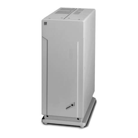
Dionex PDA-100 User manual

PDA-100 PHOTODIODE ARRAY DETECTOR
OPERATOR'S MANUAL
©2003 Dionex Corporation
Document No. 031644
Revision 02
September 2003

©2003 by Dionex Corporation
All rights reserved worldwide.
Printed in the United States of America.
This publication is protected by federal copyright law. No part of this publication
may be copied or distributed, transmitted, transcribed, stored in a retrieval system, or
transmitted into any human or computer language, in any form or by any means,
electronic, mechanical, magnetic, manual, or otherwise, or disclosed to third parties
without the express written permission of Dionex Corporation, 1228 Titan Way,
Sunnyvale, California 94088-3603 U.S.A.
DISCLAIMER OF WARRANTY AND LIMITED WARRANTY
THIS PUBLICATION IS PROVIDED “AS IS” WITHOUT WARRANTY OF
ANY KIND. DIONEX CORPORATION DOES NOT WARRANT,
GUARANTEE, OR MAKE ANY EXPRESS OR IMPLIED
REPRESENTATIONS REGARDING THE USE, OR THE RESULTS OF THE
USE, OF THIS PUBLICATION IN TERMS OF CORRECTNESS, ACCURACY,
RELIABILITY, CURRENTNESS, OR OTHERWISE. FURTHER, DIONEX
CORPORATION RESERVES THE RIGHT TO REVISE THIS PUBLICATION
AND TO MAKE CHANGES FROM TIME TO TIME IN THE CONTENT
HEREINOF WITHOUT OBLIGATION OF DIONEX CORPORATION TO
NOTIFY ANY PERSON OR ORGANIZATION OF SUCH REVISION OR
CHANGES.
TRADEMARKS
BioLC, Chromeleon, DX-LAN, PeakNet, and Summit are trademarks or registered
trademarks of Dionex Corporation.
Teflon and Tefzel are registered trademarks of E.I. duPont de Nemours & Company.
PRINTING HISTORY
Revision 01, May 2000
Revision 02, September 2003

Doc. 031644-02 9/03 i
Contents
1 • Introduction
1.1 Product Overview . . . . . . . . . . . . . . . . . . . . . . . . . . . . . . . . . . . . . . . . .1-1
1.2 Theory of Photodiode Array Detection . . . . . . . . . . . . . . . . . . . . . . . . .1-2
1.2.1 Advantages of Photodiode Array Detection . . . . . . . . . . . . . . .1-2
1.3 About This Manual . . . . . . . . . . . . . . . . . . . . . . . . . . . . . . . . . . . . . . . .1-5
1.3.1 Safety Messages and Notes . . . . . . . . . . . . . . . . . . . . . . . . . . .1-6
1.4 Safety Labels . . . . . . . . . . . . . . . . . . . . . . . . . . . . . . . . . . . . . . . . . . . . .1-8
2•Description
2.1 Front Panel . . . . . . . . . . . . . . . . . . . . . . . . . . . . . . . . . . . . . . . . . . . . . . .2-1
2.2 Inside Front Panel . . . . . . . . . . . . . . . . . . . . . . . . . . . . . . . . . . . . . . . . .2-3
2.3 Optical System . . . . . . . . . . . . . . . . . . . . . . . . . . . . . . . . . . . . . . . . . . . .2-4
2.3.1 Flow Cell . . . . . . . . . . . . . . . . . . . . . . . . . . . . . . . . . . . . . . . . .2-6
2.4 Electronics . . . . . . . . . . . . . . . . . . . . . . . . . . . . . . . . . . . . . . . . . . . . . . .2-7
2.5 Rear Panel . . . . . . . . . . . . . . . . . . . . . . . . . . . . . . . . . . . . . . . . . . . . . .2-10
3 • Operation and Maintenance
3.1 Operating Guidelines . . . . . . . . . . . . . . . . . . . . . . . . . . . . . . . . . . . . . . .3-1
3.1.1 Mobile Phases . . . . . . . . . . . . . . . . . . . . . . . . . . . . . . . . . . . . . .3-1
3.1.2 Solvent Delivery System . . . . . . . . . . . . . . . . . . . . . . . . . . . . .3-2
3.2 Getting Started . . . . . . . . . . . . . . . . . . . . . . . . . . . . . . . . . . . . . . . . . . . .3-4

PDA-100 Photodiode Array Detector
ii Doc. 031644-02 9/03
3.3 Routine Operation . . . . . . . . . . . . . . . . . . . . . . . . . . . . . . . . . . . . . . . . . 3-5
3.3.1 Panel Control . . . . . . . . . . . . . . . . . . . . . . . . . . . . . . . . . . . . . . 3-5
3.3.2 Programmed Control . . . . . . . . . . . . . . . . . . . . . . . . . . . . . . . . 3-9
3.4 Optimizing Detector Performance . . . . . . . . . . . . . . . . . . . . . . . . . . . 3-15
3.5 Stand-Alone Analog Operation . . . . . . . . . . . . . . . . . . . . . . . . . . . . . 3-28
3.6 Routine Maintenance . . . . . . . . . . . . . . . . . . . . . . . . . . . . . . . . . . . . . 3-29
4 • Troubleshooting
4.1 Flashing LED . . . . . . . . . . . . . . . . . . . . . . . . . . . . . . . . . . . . . . . . . . . . 4-1
4.2 No Detector Response . . . . . . . . . . . . . . . . . . . . . . . . . . . . . . . . . . . . . 4-2
4.3 Noisy Baseline . . . . . . . . . . . . . . . . . . . . . . . . . . . . . . . . . . . . . . . . . . . 4-3
4.4 Drifting Baseline . . . . . . . . . . . . . . . . . . . . . . . . . . . . . . . . . . . . . . . . . . 4-6
4.5 Lamp Does Not Light or Lamp LED Is Flashing . . . . . . . . . . . . . . . . . 4-7
4.6 Deuterium Lamp Intensity Count Too Low . . . . . . . . . . . . . . . . . . . . . 4-7
4.7 Wavelength Calibration Fails . . . . . . . . . . . . . . . . . . . . . . . . . . . . . . . . 4-8
4.8 Wavelength Verification Fails . . . . . . . . . . . . . . . . . . . . . . . . . . . . . . . 4-9
4.9 Faulty DX-LAN Communication . . . . . . . . . . . . . . . . . . . . . . . . . . . . 4-10
4.10 No Spectra Collected . . . . . . . . . . . . . . . . . . . . . . . . . . . . . . . . . . . . . 4-10
4.11 Low Spectral Resolution . . . . . . . . . . . . . . . . . . . . . . . . . . . . . . . . . . 4-10
4.12 Peaks Too Large or Small . . . . . . . . . . . . . . . . . . . . . . . . . . . . . . . . . 4-11
4.13 Poor Peak Shape . . . . . . . . . . . . . . . . . . . . . . . . . . . . . . . . . . . . . . . . . 4-12
4.14 Error Message: Not Enough Light to Perform Operation . . . . . . . . . 4-13
4.15 Diagnostics . . . . . . . . . . . . . . . . . . . . . . . . . . . . . . . . . . . . . . . . . . . . . 4-14
4.15.1 Moduleware Run-Time Diagnostics . . . . . . . . . . . . . . . . . . . 4-14

Contents
Doc. 031644-02 9/03 iii
4.15.2 Software Diagnostics and Calibration . . . . . . . . . . . . . . . . . .4-14
5•Service
5.1 Liquid Leaks . . . . . . . . . . . . . . . . . . . . . . . . . . . . . . . . . . . . . . . . . . . . .5-1
5.2 Cleaning the Flow Cell . . . . . . . . . . . . . . . . . . . . . . . . . . . . . . . . . . . . .5-2
5.3 Removing Trapped Air from the Flow Cell . . . . . . . . . . . . . . . . . . . . .5-2
5.4 Removing the Flow Cell . . . . . . . . . . . . . . . . . . . . . . . . . . . . . . . . . . . .5-3
5.5 Replacing the Flow Cell Windows . . . . . . . . . . . . . . . . . . . . . . . . . . . .5-4
5.6 Replacing the Flow Cell . . . . . . . . . . . . . . . . . . . . . . . . . . . . . . . . . . . .5-5
5.7 Replacing the Deuterium Lamp . . . . . . . . . . . . . . . . . . . . . . . . . . . . . . .5-6
5.8 Replacing the Tungsten Lamp . . . . . . . . . . . . . . . . . . . . . . . . . . . . . . . .5-9
5.9 Replacing the Main Power Fuses . . . . . . . . . . . . . . . . . . . . . . . . . . . .5-11
A • Specifications
A.1 Physical . . . . . . . . . . . . . . . . . . . . . . . . . . . . . . . . . . . . . . . . . . . . . . . . A-1
A.2 Environmental . . . . . . . . . . . . . . . . . . . . . . . . . . . . . . . . . . . . . . . . . . . A-1
A.3 Electrical . . . . . . . . . . . . . . . . . . . . . . . . . . . . . . . . . . . . . . . . . . . . . . . A-1
A.4 Detector . . . . . . . . . . . . . . . . . . . . . . . . . . . . . . . . . . . . . . . . . . . . . . . . A-2
A.5 Flow Cells . . . . . . . . . . . . . . . . . . . . . . . . . . . . . . . . . . . . . . . . . . . . . . A-3
A.6 Heat Exchangers . . . . . . . . . . . . . . . . . . . . . . . . . . . . . . . . . . . . . . . . . A-3
B • Installation
B.1 Facilities Required . . . . . . . . . . . . . . . . . . . . . . . . . . . . . . . . . . . . . . . . B-1

PDA-100 Photodiode Array Detector
iv Doc. 031644-02 9/03
B.2 Unpacking . . . . . . . . . . . . . . . . . . . . . . . . . . . . . . . . . . . . . . . . . . . . . . .B-1
B.3 Installation . . . . . . . . . . . . . . . . . . . . . . . . . . . . . . . . . . . . . . . . . . . . . .B-2
B.3.1 Power . . . . . . . . . . . . . . . . . . . . . . . . . . . . . . . . . . . . . . . . . . . .B-2
B.3.2 Flow Cell . . . . . . . . . . . . . . . . . . . . . . . . . . . . . . . . . . . . . . . . .B-3
B.3.3 Waste Line . . . . . . . . . . . . . . . . . . . . . . . . . . . . . . . . . . . . . . . .B-5
B.3.4 Detector Output (Analog). . . . . . . . . . . . . . . . . . . . . . . . . . . . .B-5
B.3.5 Relay/TTL Control . . . . . . . . . . . . . . . . . . . . . . . . . . . . . . . . . .B-6
B.3.6 DX-LAN Interface . . . . . . . . . . . . . . . . . . . . . . . . . . . . . . . . . .B-8
C • Reordering Information

Doc. 031644-02 9/03 1-1
1 • Introduction
1.1 Product Overview
The PDA-100 Photodiode Array Detector is an optical detector capable of
measuring the absorbance spectrum from 190 nm to 800 nm. A deuterium lamp
optimizes the UV range (190 nm to 380 nm) and a tungsten lamp optimizes the
visible range (380 nm to 800 nm).
When using the PDA-100, up to five single wavelengths (2D chromatograms) can
be collected without being required to collect 3D data. Collecting individual
wavelengths instead of the spectra offers two advantages: it eliminates the need to
perform extractions for runs that do not require spectral data and it conserves disk
space.
Key PDA-100 features include:
•Deuterium and tungsten lamps ensure low baseline noise, high signal
intensity, and applications flexibility in the wavelength range from 190 nm to
800 nm.
•A 1024-element photodiode array optimizes spectral resolution.
•A built-in holmium oxide filter verifies wavelength calibration accuracy.
•Front panel LEDs indicate detector status at a glance.
•Four analog outputs support data collection on alternate data collection
systems.
The PDA-100 is controlled remotely by a host computer running PeakNet®6 or
Chromeleon®software (Release 6.1 or later). The detector communicates with the
host computer via the Dionex DX-LAN™interface.

PDA-100 Photodiode Array Detector
1-2 Doc. 031644-02 9/03
To take full advantage of the capabilities of the PDA-100, order the 3D option for
the software. The 3D option is required in order to perform the following:
•3D data presentation and spectral analysis (real-time or post-run)
•Peak purity analysis with selectable criteria
•Spectral library search for positive peak identification
•Optimal integration path determination for method optimization
1.2 Theory of Photodiode Array Detection
Monochromatic variable wavelength detectors monitor eluting components of the
sample at a single wavelength (ideally, the wavelength of maximum absorbance),
whereas photodiode array (PDA) detectors scan a range of wavelengths every few
milliseconds and continually generate spectral information. Wavelength, time, and
absorbance can all be plotted.
PDA detectors provide three-dimensional information that allows an accurate
assessment of peak identity, purity, and quantitation in a single run. Software
support for PDA detectors includes peak purity and spectral library search
functions to help determine peak homogeneity and identity.
1.2.1 Advantages of Photodiode Array Detection
PDA detectors are useful in both research and quality assurance
laboratories. In the research laboratory, the PDA provides the analyst with
a variety of approaches to the analysis. In the quality assurance
laboratory, the PDA provides several results from a single run, thereby
increasing the throughput of the HPLC.
PDA detection offers the following advantages:
•Peak measurement at all wavelengths
In methods development, detailed information about the detector
conditions required for the analysis may not be known. When a
variable wavelength detector is used, a sample must often be injected
several times, with varying wavelengths, to ensure that all peaks are
detected. When a PDA detector is used, a wavelength range can be
programmed and all compounds that absorb within this range can be
detected in a single run.

1 • Introduction
Doc. 031644-02 9/03 1-3
•Determination of the correct wavelengths in one run
After all peaks have been detected, the maximum absorbance
wavelength for each peak can be determined. A PDA detector can
collect spectra of each peak and calculate the absorbance maximum.
•Detection of multiple wavelengths
A PDA detector can monitor a sample at more than one wavelength.
This is especially useful when the wavelength maxima of the analytes
are different. Wavelengths can be selected to analyze each compound
at its highest sensitivity.
•Peak purity analysis
It is difficult to determine component purity from a chromatogram.
However, a PDA detector can analyze peak purity by comparing
spectra within a peak. A pure peak has matching spectra throughout
the peak (at all wavelengths).
•Positive peak identification
In liquid chromatography, peak identification is usually based on
relative retention times. When a PDA detector is used, spectra are
automatically collected as each peak elutes. The PDA software
compares the spectra with those stored in a library to determine the
best fit matches; this method increases the likelihood of correctly
identifying peaks.
For example, Figure 1-1 shows an overlay of pyrene and an impurity
(obtained from two consecutive chromatographic runs). Based on 2D
data, or if the run had been performed with a conventional variable
wavelength detector, these peaks would have been misidentified as
the same component.
A PDA-100, under the control of Dionex software with the 3D
option, correctly identified and differentiated the components. The
spectra of pyrene and the impurity (see Figure 1-2) clearly indicate
that the two peaks are different components.

PDA-100 Photodiode Array Detector
1-4 Doc. 031644-02 9/03
Figure 1-1. Overlay of Pyrene and an Impurity
Figure 1-2. Spectra of Pyrene and an Impurity
Impurity
Pyrene
Impurity
Pyrene

1 • Introduction
Doc. 031644-02 9/03 1-5
1.3 About This Manual
Chapter 1
Introduction
Provides a brief overview of the PDA-100 and the theory
of photodiode array detection. Summarizes the
organization of the user’s manual. Explains the meaning of
safety messages and icons in the manual and the safety
labels on the detector.
Chapter 2
Description
Describes the PDA-100 front panel LED indicators, inside
front panel, optical system, and rear panel connections.
Chapter 3
Operation and
Maintenance
Presents an overview of PDA-100 operation, as well as
guidelines for optimizing detector performance. Lists
routine preventive maintenance procedures.
Chapter 4
Troubleshooting
Lists problems that may occur, along with step-by-step
instructions for resolving them.
Chapter 5
Service
Contains step-by-step instructions for routine service and
parts replacement procedures.
Appendix A
Specifications
Lists the PDA-100 specifications and installation site
requirements.
Appendix B
Installation
Describes how to install the PDA-100, including the DX-
LAN connections to the host computer running Dionex
chromatography software.
Appendix C
Reordering
Information
Lists spare parts for the detector.

PDA-100 Photodiode Array Detector
1-6 Doc. 031644-02 9/03
1.3.1 Safety Messages and Notes
This manual contains warnings and precautionary statements that can
prevent personal injury and/or damage to the PDA-100 when properly
followed. Safety messages appear in bold type and are accompanied by
icons, as shown below.
Indicates an imminently hazardous situation which, if not avoided, will
result in death or serious injury.
Indicates a potentially hazardous situation which, if not avoided, may
result in death or serious injury.
Indicates a potentially hazardous situation which, if not avoided, may
result in minor or moderate injury.
Indicates that the function or process of the instrument may be
impaired. Operation does not constitute a hazard.

1 • Introduction
Doc. 031644-02 9/03 1-7
Messages d’avertissement en français
Warnhinweise in Deutsch
Informational messages also appear throughout this manual. These are
labeled NOTE and are in bold type:
NOTE NOTES call attention to certain information. They alert
the user to an unexpected result of an action, suggest
how to optimize instrument performance, etc.
Signale une situation de danger immédiat qui, si elle n'est pas évitée,
entraînera des blessures graves à mortelles.
Signale une situation de danger potentiel qui, si elle n'est pas évitée,
pourrait entraîner des blessures graves à mortelles.
Signale une situation de danger potentiel qui, si elle n'est pas évitée,
pourrait entraîner des blessures mineures à modérées. Également
utilisé pour signaler une situation ou une pratique qui pourrait
gravement endommager l'instrument mais qui n'entraînera pas de
blessures.
Bedeutet unmittelbare Gefahr. Mißachtung kann zum Tod oder
schwerwiegenden Verletzungen führen.
Bedeutet eine mögliche Gefährdung. Mißachtung kann zum Tod oder
schwerwiegenden Verletzungen führen.
Bedeutet eine mögliche Gefährdung. Mißachtung kann zu kleineren
oder mittelschweren Verletzungen führen. Wird auch verwendet, wenn
eine Situation zu schweren Schäden am Gerät führen kann, jedoch
keine Verletzungsgefahr besteht.

PDA-100 Photodiode Array Detector
1-8 Doc. 031644-02 9/03
1.4 Safety Labels
The TUV GS, C, US Mark safety label and the CE Mark label on the PDA-100
indicate that the PDA-100 is in compliance with the following standards: EN
61010-1:1993 (safety), CAN/CSA-C22.2 No. 1010.1-92 (safety), UL 3101-
1/10.93 (safety), EN 50082-1:1992 (susceptibility), and EN 55011:1991
(emissions).
These symbols appear on the PDA-100 or on PDA-100 labels.
Alternating current
Protective conductor terminal
Power supply is on
Power supply is off
˜

Doc. 031644-02 9/03 2-1
2 • Description
2.1 Front Panel
Figure 2-1 illustrates the front panel of the PDA-100 Photodiode Array Detector.
The Power switch provides on/off control of the detector power. LED indicators
identify the status of four functions: the detector power, the deuterium and
tungsten lamps, and the run. A solid lighted LED indicates that the corresponding
function is in progress. A flashing LED indicates that an error occurred; for an
explanation, check the Audit Trail in PeakNet 6 or Chromeleon.
Figure 2-1. PDA-100 Front Panel
LED LED Status Function
Run Lighted Data is being acquired by the host computer.
Flashing An alarm was activated; for example, the leak sensor in
the drip tray may have been triggered.
Off Data is not being acquired by the host computer.
Deuterium Lighted The deuterium lamp is on.
Flashing A command was issued to turn on the deuterium lamp,
but the lamp failed to turn on (see Section 4.5).
Off The deuterium lamp is off.
Run
Deuterium
Tungsten
Power
PDA-100 Photodiode Array Detector

PDA-100 Photodiode Array Detector
2-2 Doc. 031644-02 9/03
Tungsten Lighted The tungsten lamp is on.
Flashing A command was issued to turn on the tungsten lamp, but
the lamp failed to turn on (see Section 4.5).
Off The tungsten lamp is off.
Power Lighted The detector power is on. Press the Power switch to turn
the detector on and off.
Flashing The detector failed one of the electrical checks or optical
checks performed during the power-up sequence (see
Section 4.15.1).
Off The detector power is off. Press the Power switch to
turn the detector on and off.
LED LED Status Function

2 • Description
Doc. 031644-02 9/03 2-3
2.2 Inside Front Panel
NOTE For an illustration of the inside front panel with the flow
cell cover and lamp cover removed, see Figure 5-1.
Grasp the PDA-100 front panel by the sides and pull straight off to access the
inside front panel (see Figure 2-2).
•The flow cell cover protects the cell from dust, ambient light, fluctuations in
ambient temperature, and vibration.
•The lamp cover enhances the thermal stabilization of the optical bench. The
optical bench is housed in a compartment behind the inside front panel.
•Because the flow cell is located behind a cover, leaks from the cell tubing
connections are not immediately apparent. To prevent damage to detector
components, the bottom of the optical bench contains a built-in leak tray. A
sensor in the sump of the leak tray responds to changes in the index of
refraction when wet.
If the leak sensor is activated, it triggers an alarm in the detector and the front
panel Run LED begins flashing (see Figure 2-1). In addition, the leak is
reported to the host computer and PeakNet 6 or Chromeleon displays an error
message.
Figure 2-2. PDA-100 Inside Front Panel
Power
Switch
Component Identification
Label
Leak
Sensor
Flow Cell
Cover
Lamp Cover
056345-01
Sensor
Leak
Lamp
Tung st en
Lamp
Deuterium
Cell
Flow
INJURY.
CAUSE PERMANENT EYE
INTENSE LIGHT MAY
INTO LIGHT SOURCES.
AVOID LOOKIN G DIRECTLY
WARNING
On/Off
Power
Run
Deuterium
Tungsten
Power

PDA-100 Photodiode Array Detector
2-4 Doc. 031644-02 9/03
2.3 Optical System
Figure 2-3 is a schematic of the PDA-100 optical system.
Light from the tungsten lamp is focused through an opening in the internal
structure of the deuterium lamp. Light from the tungsten and deuterium lamps is
then focused through the flow cell by the source lens. After exiting the cell, the
light passes through the spectrograph lens to the filter paddle and is focused into
the slit. The light then passes through the slit to the grating, where it is separated
into its component wavelengths and diffracted to the photodiode array. Each diode
measures a narrow portion of the spectrum.
Figure 2-3. PDA-100 Optical System
Grating Slit
Flow Cell
Filter Paddle
Photodiode Array
Spectrograph Lens
Source Lens
Vi
s
ibl
e
F
ocus Lens
Deuterium Lamp
Tungsten Lamp

2 • Description
Doc. 031644-02 9/03 2-5
Optical System
Component
Function
Tungsten Lamp The light source for visible and near-infrared wavelengths
(380 nm to 800 nm). The tungsten lamp is focused through an
opening in the internal structure of the deuterium lamp; this
allows the lamps to share the optical axis to the source lens.
Visible Focus Lens Focuses the visible light from the tungsten lamp to the through-
hole of the deuterium lamp.
Deuterium Lamp The light source for UV wavelengths (190 nm to 380 nm); also
used to check the wavelength calibration.
Source Lens Receives the light from the tungsten and deuterium lamps and
focuses it so that the beam passes through the flow cell.
Flow Cell The measurement site for sample absorbance. The cell has a flat
window on each side.
Spectrograph Lens Receives the light from the flow cell and focuses it onto the slit.
Filter Paddle The motorized filter paddle in the spectrograph has three
positions:
•Open = Light passes, unobstructed, along the light path when
the holmium oxide filter is moved out of the light path.
•Blocked = No light passes along the light path; used to
measure the dark signal without turning off the lamps.
•Holmium = Places the holmium oxide filter in the light path;
used to verify wavelength accuracy.
Slit The width of the slit (equivalent to 1 nm) optimizes the optical
resolution.
Grating Diffracts the light beam into its component wavelengths and
directs the light onto the photodiode array.
Photodiode Array A series of 1024 photosensitive elements. Each element measures
a narrow band of the spectrum. A spectrum is obtained by
measuring the light intensity of each wavelength and reporting the
range of results.

PDA-100 Photodiode Array Detector
2-6 Doc. 031644-02 9/03
2.3.1 Flow Cell
The PDA-100 flow cell assembly (see Figure 2-4) is available in PEEK or
stainless steel. Two built-in heat exchangers, one on the cell inlet tubing
and one on the cell handle, help stabilize the temperature of the mobile
phase before it enters the cell.
Figure 2-4. Flow Cell Assembly
Flow Cell Cell Path Length Cell Volume Heat Exchanger Volume
PEEK
(P/N 056346)
10 mm 13 µL20µL
Stainless Steel
(P/N 056126)
10 mm 13 µL9µL
Do not touch the cell windows. If you touch a window, clean it with
denatured alcohol and a clean lens tissue.
Do not use the PEEK flow cell with normal phase or chlorinated
solvents; these solvents will damage the cell.
Do not use the stainless steel flow cell with high pH salts; the salts
can cause corrosion, contamination, and metal leaching.
Cell Inlet Tubing
Cell Outlet Tubing
Heat Exchangers
Flow Cell
Handle
Sprin
g
Clip
Table of contents
Other Dionex Security Sensor manuals
Popular Security Sensor manuals by other brands

Bosch
Bosch AVENAR detector4000 user manual
Inventronics
Inventronics QBM D4I LS HB manual
Honeywell
Honeywell 5800COMBO Installation and setup guide

Sentrol
Sentrol 5150-W - Security Glassbreak Shock Sensor installation instructions
Inficon
Inficon HLD6000 Translation of the original operating instructions
Emerson
Emerson Rosemount CT4215 Reference manual
