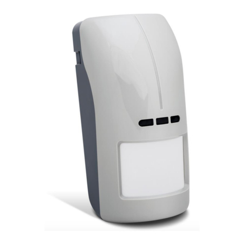
Satel SLIM-PIR-LUNA-PET User manual

SLIM-PIR-LUNA-PET
Digital passive infrared detector
with lighting feature
and pet immunity up to 20 kg
Firmware version 1.00 slim-pir-luna-pet_en 10/19
SATEL sp. z o.o. • ul. Budowlanych 66 • 80-298 Gdańsk • POLAND
tel. +48 58 320 94 00
www.satel.eu

IMPORTANT
The device should be installed by qualified personnel.
Prior to installation, please read carefully this manual.
Changes, modifications or repairs not authorized by the manufacturer shall void your rights
under the warranty.
SATEL aims to continually improve the quality of its products, which may result in changes in
their technical specifications and software. Current information about the changes being
introduced is available on our website.
Please visit us at:
http://www.satel.eu
The declaration of conformity may be consulted at www.satel.eu/ce
The following symbols may be used in this manual:
- note,
- caution.

CONTENTS
1. Features ...........................................................................................................................2
2. Description........................................................................................................................2
Lighting feature.................................................................................................................2
Supervision features......................................................................................................... 2
LED indicators ..................................................................................................................3
Remote switching between PIR sensor sensitivity............................................................3
Remote configuration mode enable/disable...................................................................... 3
3. Electronics module ...........................................................................................................3
4. Terminal block ..................................................................................................................5
5. Selecting a mounting location...........................................................................................6
6. Installation ........................................................................................................................7
7. Configuring the detector ................................................................................................... 9
Starting configuration mode..............................................................................................9
Running functions and configuring parameters ................................................................9
Ending configuration mode ............................................................................................. 10
8. Start-up and walk test .....................................................................................................11
9. Specifications .................................................................................................................11

2 SLIM-PIR-LUNA-PET SATEL
The SLIM-PIR-LUNA-PET detector detects movement in the protected area. Additionally, the
detector has a set of LEDs to provide the lighting feature. This manual applies to the detector
with electronics version D.
1. Features
Motion detection with passive infrared sensor (PIR).
Adjustable detection sensitivity.
Digital motion detection algorithm.
Digital temperature compensation.
Pet immunity up to 20 kg.
Wide-angle lens designed specially for SLIM detectors.
Ability to configure the detector settings using the OPT-1 keyfob.
Built-in end-of-line resistors (2EOL: 2 x 1.1 k/ 2 x 4.7 k/ 2 x 5.6 k).
Lighting feature implemented using LEDs.
Option to remotely control lighting or activate lighting by motion.
LED indicators.
Selectable color of LED indicators light (7 colors available).
Remote LED indicators enable/disable.
Remote configuration mode enable/disable.
Supervision of motion detection system and supply voltage.
Tamper protection against enclosure opening and removal from mounting surface.
2. Description
The detector will report alarm when the infrared sensor (PIR) detects motion.
Lighting feature
The light sources are 4 white LEDs. The following lighting operation modes are available:
remote control only – the lighting is ON when the LUNA terminal is connected to common
ground (if the LUNA terminal is disconnected from ground, the lighting is OFF),
remote control and motion activation – the lighting is ON when the LUNA terminal is
connected to ground, or after motion is sensed by the detector,
motion activation if the LUNA terminal is connected to common ground – the lighting is
ON when the LUNA terminal is connected to common ground and the detector has
sensed motion (if the LUNA terminal is disconnected from common ground, detection of
motion will not activate the lighting).
If activated by motion, the lighting remains ON for the time period programmed in the
detector. If the lighting is ON and motion is detected, the countdown starts anew.
For description of the lighting feature configuration, see section “Configuring the detector”.
Supervision features
In the event of the voltage drop below 9 V (±5%) for more than 2 seconds or the motion
detection system failure, the detector will signal a trouble. The trouble is indicated by the
alarm relay activation and the LED indicators coming on. Signaling will continue as long as
the trouble exists.

SATEL SLIM-PIR-LUNA-PET 3
LED indicators
The LEDs indicate:
warm-up – flashing alternately different colors for about 30 seconds;
alarm – ON for 2 seconds (default color: blue);
trouble – steady ON for entire duration of the trouble (the same color of lighting as in case
of alarm).
You can change the color. You can select one of seven available colors (see “Configuring the
detector”).
Enabling the LEDs by using a jumper
If you put a jumper across the LED pins, the LEDs will be enabled, i.e. they will indicate the
above described events (the LED indicators can’t be enabled/disabled remotely). If you do
not put a jumper across the pins, the LEDs will be disabled, but they can be enabled/disabled
remotely.
Remote LEDs enable/disable
The LED terminal is provided to allow remote LEDs enable/disable. When the terminal is
connected to common ground, the LEDs are enabled. When the terminal is disconnected
from common ground, the LEDs are disabled.
If the detector is used in the INTEGRA / INTEGRA Plus alarm system, you can connect to
the terminal an OC type control panel output programmed e.g. as “Zone test status” or “BI
switch”.
Remote switching between PIR sensor sensitivity
The SENS terminal is provided to allow remote switching between PIR sensor detection
sensitivity. The first sensitivity is used when the terminal is disconnected from common
ground, and the second – when the terminal is connected to common ground.
This makes it possible to change the PIR sensor sensitivity depending on the state of
partition to which the detector is assigned. If the partition is disarmed, the maximum
sensitivity can be set to increase the efficiency of lighting activation by motion. If the partition
is armed, the lower sensitivity can be set to eliminate false alarms.
If the detector is working in the INTEGRA / INTEGRA Plus alarm system, you can connect to
the terminal the control panel OC type output programmed e.g. as “Armed status”.
For description of how to configure PIR sensor sensitivity, see section “Configuring the
detector”.
Remote configuration mode enable/disable
The SRVC terminal is provided to allow remote configuration mode enable/disable. The
configuration mode is enabled, when the terminal is connected to the common ground.
If the detector is working in the INTEGRA / INTEGRA Plus alarm system, you can connect to
the terminal the control panel OC type output programmed e.g. as “Service mode status” or
“BI switch”.
3. Electronics module
Do not remove the plastic cover from the circuit board to prevent damage to the
components located on the board.
Do not touch the pyroelectric sensor, so as not to soil it.
4 SLIM-PIR-LUNA-PET SATEL
pins for configuration of the detector outputs. Available settings are shown in the figures:
2 – 2 x 1.1 kresistors are used,
3 – 2 x 4.7 kresistors are used,
4 – 2 x 5.6 kresistors are used,
5 – built-in resistors are not used.
If the built-in resistors are used, connect the detector outputs as shown in Fig. 11. When
the built-in resistors are not used, connect the detector outputs as shown in Fig. 10.
infrared receiver allowing to configure the detector by means of OPT-1 keyfob. The
keyfob is available in SATEL's product range.
MODE button used for configuring the detector (see “Configuring the detector”).
tamper switch activated by cover removal.
buttons used for configuring the detector (see “Configuring the detector”).
LED indicators.
PIR sensor (quad element pyrosensor).
pins to enable/disable the LED indicators.
LEDs for lighting.
On the other side of the electronics module is a tamper switch activated by removing the
detector from the wall.

SATEL SLIM-PIR-LUNA-PET 5
4. Terminal block
The terminal block is located on the enclosure base (Fig. 6). To get access to the terminals,
you must remove the electronics module (Fig. 8).
SENS - switching between PIR sensor sensitivity.
TMP - tamper output (NC relay).
NC - alarm output (NC relay).
COM - common ground.
+12V - power input.
LED - enable/disable the LED indicators.
SRVC - enable/disable the detector configuration mode.
LUNA - LED lighting control.

6 SLIM-PIR-LUNA-PET SATEL
5. Selecting a mounting location
Do not install the detector outdoors (A).
Install the detector at the recommended height (B).
When choosing the installation location, keep in mind that the detector performance will
be the best where the expected direction of the intruder movement will be across the
coverage pattern (C).
Do not install the detector in places where it will be exposed to direct sunlight (D) or light
reflected from other objects (E).
Do not point the detector towards fans (F), air conditioners (G) or heat sources (H).

SATEL SLIM-PIR-LUNA-PET 7
6. Installation
Disconnect power before making any electrical connections.
If the detector is to be pet immune, it must not be mounted on the bracket and
must be installed at a height of 2.4 m with no inclination from the vertical.
1. Remove the front cover (Fig. 7).
2. Move the electronics module down to unlock it, and then remove it from the enclosure
base (Fig. 8).
3. Make the openings for screws (Fig. 9) and cable in the enclosure base.
4. Pass the cable through the prepared opening.
5. Secure the enclosure base to the wall (Fig. 9). The wall plugs (anchors) delivered with the
device are intended for concrete, brick, etc. For other types of surface (drywall,
styrofoam), use the appropriately selected wall plugs.
6. Connect the wires to the corresponding terminals.
7. Place the electronics module in the enclosure base and then move it up to lock it.
8. Configure the detector (see “Configuring the detector”).
9. Replace the cover.

8 SLIM-PIR-LUNA-PET SATEL

SATEL SLIM-PIR-LUNA-PET 9
7. Configuring the detector
To configure the detector, you can use the buttons on the electronics module or the OPT-1
keyfob.
The OPT-1 keyfob is available in SATEL's product range.
Starting configuration mode
Press the MODE button on the detector electronics module for 3 seconds or connect the
SRVC terminal to common ground. After starting the configuration mode, the LEDs will start
flashing red. The number of flashes means the number of function you can run (see Table 1).
Pressing and holding down the -and +buttons simultaneously for 3 seconds in the
configuration mode will restore the factory default settings of the detector.
In the configuration mode, the LED lighting is OFF.
Running functions and configuring parameters
1. Use the buttons on the electronics module (+- next function; -- previous function) or the
keyfob keys ( - next function; - previous function) to find a function you want to run.
2. Press the MODE button on the electronics module or the key on the keyfob to run a
function. After starting the function, the LEDs will start flashing green. The number of
flashes means the value currently set for the parameter being configured (see Table 1).
3. Use the buttons on the electronics module (+- next value; -- previous value) or the
keyfob keys ( - next value; - previous value) to configure the selected parameter.
4. Press the MODE button on the electronics module or the key on the keyfob to save the
changes. When the new parameter value is saved, the LEDs will start flashing red to
inform you that you have returned to the function list.
Function
number Description of parameter to be programmed
1
First PIR sensor sensitivity
You can program from 1to 16 (1 - minimum; 16 – maximum).
By default: 8.
When the function is running, detection of motion by the PIR sensor is indicated
by the LEDs coming on red for 2 seconds. This enables the PIR sensor
coverage area to be tested for the selected sensitivity.
2
Second PIR sensor sensitivity
You can program from 1to 16 (1 - minimum; 16 – maximum).
By default: 8.
When the function is running, detection of motion by the PIR sensor is indicated
by the LEDs coming on red for 2 seconds. This enables the PIR sensor
coverage area to be tested for the selected sensitivity.

10 SLIM-PIR-LUNA-PET SATEL
Function Description of parameter to be programmed
number
3
LED indicators light color when indicating alarm / trouble
You can program from 1to 7(1-7 – color).
By default: 3(blue).
In addition to the presentation of value (flashing green), the LEDs show the
color assigned to that value (for 2 seconds).
4
Lighting operation modes
You can program 1(remote control only), 2(remote control and activation by
motion) or 3(activation by motion if the LUNA terminal is connected to
common ground).
By default: 1(remote control only).
5 Duration of motion activated lighting
You can program 1(5 s), 2(15 s), 3(30 s), 4(60 s), 5(90 s) or 6 (180 s).
By default: 3(30 s).
6 Method of lighting turning off
You can program 1(instant turn off) or 2(slow dim down).
By default: 2(slow dim down).
Table 1
The color of LED light has an impact on the current consumption by the detector. The
red, green and blue colors ensure the lowest current consumption. Selecting other
colors will increase the current consumption by as much as several milliamperes.
Ending configuration mode
Press the MODE button on the electronics module for 3 seconds or disconnect the SRVC
terminal from common ground.
If you started the configuration mode by using the MODE button, the configuration
mode will be ended automatically 20 minutes after the last operation performed by the
user.

SATEL SLIM-PIR-LUNA-PET 11
8. Start-up and walk test
The LED indicators should be enabled during the walk test (see “LED indicators”).
1. Power on the detector. The LEDs will flash alternately different colors for 30 seconds to
indicate warm-up of the detector.
2. When the LEDs stop flashing, check that moving within the detector coverage area will
make the LED to turn on. Figure 12 shows the maximum coverage area and the creep
zone of a detector installed at a height of 2.4 m.
9. Specifications
Supply voltage .................................................................................................... 12 VDC ±15%
Standby current consumption ..........................................................................................13 mA
Maximum current consumption........................................................................................97 mA
EOL resistors ..................................................................... 2 x 1.1 k/ 2 x 4.7 k/ 2 x 5.6 k,
Outputs
alarm (NC relay, resistive load) ................................................................... 40 mA / 24 VDC
tamper (NC relay, resistive load) ................................................................. 40 mA / 24 VDC
Detectable speed...................................................................................................... 0.3...3 m/s
Alarm signaling period ..........................................................................................................2s
Warm-up period ..................................................................................................................30s
Recommended installation height..................................................................................... 2.4 m
Coverage area ................................................................................................ 12 m x 13 m, 90°
Security grade according to EN 50131-2-2................................................................... Grade 2

12 SLIM-PIR-LUNA-PET SATEL
Compliance with standards .................. EN 50131-1, EN 50131-2-2, EN 50130-4, EN 50130-5
Environmental class according to EN 50130-5 ........................................................................II
Operating temperature range...............................................................................-10°C...+55°C
Maximum humidity ..........................................................................................................93±3%
Dimensions ................................................................................................... 62 x 137 x 42 mm
Weight...............................................................................................................................142 g
5 year warranty from date of manufacture
Table of contents
Other Satel Security Sensor manuals

Satel
Satel SPL-TO User manual

Satel
Satel IVORY User manual

Satel
Satel AQUA RING S User manual

Satel
Satel AMD-103 User manual

Satel
Satel AQUA PET User manual

Satel
Satel MGD-300 User manual

Satel
Satel VD-1 User manual

Satel
Satel APD-100 User manual

Satel
Satel ADD-200 User manual

Satel
Satel ACTIVA-2 User manual

Satel
Satel SLIM-PIR-PET User manual

Satel
Satel A D-200 Series User manual

Satel
Satel AOD-200 User manual

Satel
Satel APMD-150 User manual

Satel
Satel OPAL Pro User manual

Satel
Satel ARD-100 User manual

Satel
Satel AFD-100 User manual

Satel
Satel INDIGO User manual

Satel
Satel SILVER User manual

Satel
Satel TD-1 User manual