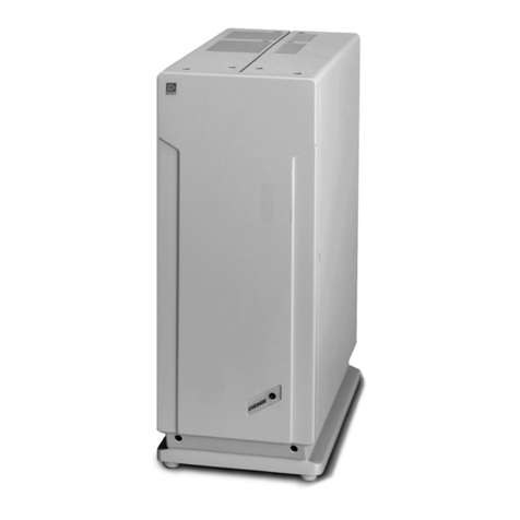
Dionex CD25 User manual

CD25 CONDUCTIVITY DETECTOR
OPERATOR'S MANUAL
© 2000 Dionex Corporation
Document No. 031687
Revision 01
April 2000

©2000 by Dionex Corporation
All rights reserved worldwide.
Printed in the United States of America.
This publication is protected by federal copyright law. No part of this publication
may be copied or distributed, transmitted, transcribed, stored in a retrieval system, or
transmitted into any human or computer language, in any form or by any means,
electronic, mechanical, magnetic, manual, or otherwise, or disclosed to third parties
without the express written permission of Dionex Corporation, 1228 Titan Way,
Sunnyvale, California 94088-3603 U.S.A.
DISCLAIMER OF WARRANTY AND LIMITED WARRANTY
THIS PUBLICATION IS PROVIDED “AS IS” WITHOUT WARRANTY OF
ANY KIND. DIONEX CORPORATION DOES NOT WARRANT,
GUARANTEE, OR MAKE ANY EXPRESS OR IMPLIED
REPRESENTATIONS REGARDING THE USE, OR THE RESULTS OF THE
USE, OF THIS PUBLICATION IN TERMS OF CORRECTNESS, ACCURACY,
RELIABILITY, CURRENTNESS, OR OTHERWISE. FURTHER, DIONEX
CORPORATION RESERVES THE RIGHT TO REVISE THIS PUBLICATION
AND TO MAKE CHANGES FROM TIME TO TIME IN THE CONTENT
HEREINOF WITHOUT OBLIGATION OF DIONEX CORPORATION TO
NOTIFY ANY PERSON OR ORGANIZATION OF SUCH REVISION OR
CHANGES.
TRADEMARKS
Teflon® and Tefzel® are registered trademarks of E.I. duPont de Nemours & Co.
AutoSuppression™, DX-LAN™, IonSep®, MPIC™, OmniPac®, OnGuard™,
SRS®, and Self-Regenerating Suppressor® are trademarks of Dionex Corp.
PRINTING HISTORY
Revision 01, April 2000

Doc. 031687-01 4/2000 i
1 • Introduction
1.1 Overview . . . . . . . . . . . . . . . . . . . . . . . . . . . . . . . . . . . . . . . . . . . . . . . .1-1
1.2 About This Manual . . . . . . . . . . . . . . . . . . . . . . . . . . . . . . . . . . . . . . . .1-2
1.2.1 Typefaces . . . . . . . . . . . . . . . . . . . . . . . . . . . . . . . . . . . . . . . . .1-3
1.2.2 Safety Messages and Notes . . . . . . . . . . . . . . . . . . . . . . . . . . .1-3
1.3 Safety Labels . . . . . . . . . . . . . . . . . . . . . . . . . . . . . . . . . . . . . . . . . . . . .1-4
2 • Description
2.1 Front Control Panel . . . . . . . . . . . . . . . . . . . . . . . . . . . . . . . . . . . . . . . .2-1
2.1.1 Control Panel Display . . . . . . . . . . . . . . . . . . . . . . . . . . . . . . .2-1
2.1.2 Control Panel Keypad . . . . . . . . . . . . . . . . . . . . . . . . . . . . . . .2-2
2.1.3 Initial Display Screens . . . . . . . . . . . . . . . . . . . . . . . . . . . . . . .2-6
2.2 Electronics Chassis . . . . . . . . . . . . . . . . . . . . . . . . . . . . . . . . . . . . . . . .2-8
2.2.1 Connectors . . . . . . . . . . . . . . . . . . . . . . . . . . . . . . . . . . . . . . . .2-9
2.2.2 Cards . . . . . . . . . . . . . . . . . . . . . . . . . . . . . . . . . . . . . . . . . . . . .2-9
2.3 Conductivity Cell . . . . . . . . . . . . . . . . . . . . . . . . . . . . . . . . . . . . . . . . .2-12
2.3.1 DS3 Detection Stabilizer . . . . . . . . . . . . . . . . . . . . . . . . . . . .2-13
2.3.2 Shielded Cell . . . . . . . . . . . . . . . . . . . . . . . . . . . . . . . . . . . . .2-14
2.4 Rear Panel . . . . . . . . . . . . . . . . . . . . . . . . . . . . . . . . . . . . . . . . . . . . . .2-15
2.5 Functional Description . . . . . . . . . . . . . . . . . . . . . . . . . . . . . . . . . . . .2-16
2.5.1 Operating and Control Modes . . . . . . . . . . . . . . . . . . . . . . . .2-16
Contents

CD25 Conductivity Detector
ii Doc. 031687-01 4/2000
2.5.2 Local and Remote Modes . . . . . . . . . . . . . . . . . . . . . . . . . . . 2-17
2.5.3 Method Control . . . . . . . . . . . . . . . . . . . . . . . . . . . . . . . . . . . 2-17
3 • Operation and Maintenance
3.1 Getting Ready to Run . . . . . . . . . . . . . . . . . . . . . . . . . . . . . . . . . . . . . . 3-1
3.2 Running Under Direct Control (Local Mode) . . . . . . . . . . . . . . . . . . . 3-2
3.3 Running Under Method Control (Local Mode) . . . . . . . . . . . . . . . . . . 3-3
3.3.1 Running a Method . . . . . . . . . . . . . . . . . . . . . . . . . . . . . . . . . . 3-3
3.3.2 Changing the Running Method . . . . . . . . . . . . . . . . . . . . . . . . 3-3
3.3.3 Creating a New Method . . . . . . . . . . . . . . . . . . . . . . . . . . . . . . 3-4
3.3.4 Editing an Existing Method . . . . . . . . . . . . . . . . . . . . . . . . . . . 3-5
3.4 Optimizing Temperature Compensation . . . . . . . . . . . . . . . . . . . . . . . 3-7
3.4.1 With a DS3 and Conductivity Cell . . . . . . . . . . . . . . . . . . . . . 3-7
3.4.2 With a Shielded Conductivity Cell . . . . . . . . . . . . . . . . . . . . . 3-8
3.5 Routine Maintenance . . . . . . . . . . . . . . . . . . . . . . . . . . . . . . . . . . . . . . 3-8
4 • Troubleshooting
4.1 No Detector Response . . . . . . . . . . . . . . . . . . . . . . . . . . . . . . . . . . . . . 4-1
4.2 Low Detector Output . . . . . . . . . . . . . . . . . . . . . . . . . . . . . . . . . . . . . . 4-2
4.3 High Detector Output . . . . . . . . . . . . . . . . . . . . . . . . . . . . . . . . . . . . . . 4-2
4.4 Noisy or Drifting Baseline . . . . . . . . . . . . . . . . . . . . . . . . . . . . . . . . . . 4-2
4.5 Liquid Leaks from the DS3 . . . . . . . . . . . . . . . . . . . . . . . . . . . . . . . . . 4-4
4.6 DS3 Temperature Inaccurate . . . . . . . . . . . . . . . . . . . . . . . . . . . . . . . . 4-6
4.7 Conductivity Inaccurate . . . . . . . . . . . . . . . . . . . . . . . . . . . . . . . . . . . . 4-7

Contents
Doc. 031687-01 4/2000 iii
4.8 Faulty DX-LAN Communication . . . . . . . . . . . . . . . . . . . . . . . . . . . . .4-7
4.9 Diagnostics . . . . . . . . . . . . . . . . . . . . . . . . . . . . . . . . . . . . . . . . . . . . . .4-8
5•Service
5.1 Eliminating Liquid Leaks . . . . . . . . . . . . . . . . . . . . . . . . . . . . . . . . . . .5-2
5.2 Removing Trapped Air from the Cell . . . . . . . . . . . . . . . . . . . . . . . . . .5-2
5.3 Replacing the DS3 Cell . . . . . . . . . . . . . . . . . . . . . . . . . . . . . . . . . . . . .5-2
5.4 Calibrating the Cell . . . . . . . . . . . . . . . . . . . . . . . . . . . . . . . . . . . . . . . .5-4
5.5 Replacing the Main Power Fuses . . . . . . . . . . . . . . . . . . . . . . . . . . . . .5-6
A • Specifications
5.6 Physical . . . . . . . . . . . . . . . . . . . . . . . . . . . . . . . . . . . . . . . . . . . . . . . . A-1
A.1 Environmental . . . . . . . . . . . . . . . . . . . . . . . . . . . . . . . . . . . . . . . . . . . A-1
A.2 Electrical . . . . . . . . . . . . . . . . . . . . . . . . . . . . . . . . . . . . . . . . . . . . . . . A-1
A.3 Display and Keypad . . . . . . . . . . . . . . . . . . . . . . . . . . . . . . . . . . . . . . A-2
A.4 Detector . . . . . . . . . . . . . . . . . . . . . . . . . . . . . . . . . . . . . . . . . . . . . . . . A-2
A.5 Conductivity Cell . . . . . . . . . . . . . . . . . . . . . . . . . . . . . . . . . . . . . . . . . A-2
A.6 SRS Power Supply . . . . . . . . . . . . . . . . . . . . . . . . . . . . . . . . . . . . . . . A-3
A.7 DS3 Detection Stabilizer (Optional) . . . . . . . . . . . . . . . . . . . . . . . . . . A-3
B • Installation
B.1 Facility Requirements . . . . . . . . . . . . . . . . . . . . . . . . . . . . . . . . . . . . . B-1
B.2 Installation . . . . . . . . . . . . . . . . . . . . . . . . . . . . . . . . . . . . . . . . . . . . . . B-1

CD25 Conductivity Detector
iv Doc. 031687-01 4/2000
B.2.1 Power Connection . . . . . . . . . . . . . . . . . . . . . . . . . . . . . . . . . .B-1
B.2.2 DX-LAN Interface: 10BASE-T Connections (Optional). . . . .B-3
B.2.3 DX-LAN Interface: BNC Connections (Optional). . . . . . . . . .B-6
B.2.4 DS3 Detection Stabilizer Installation. . . . . . . . . . . . . . . . . . . .B-9
B.2.5 Shielded Conductivity Cell Installation . . . . . . . . . . . . . . . . . .B-9
B.2.6 DS3 or Shielded Cell Plumbing . . . . . . . . . . . . . . . . . . . . . . . .B-9
B.2.7 Recorder/Diagnostic Connection . . . . . . . . . . . . . . . . . . . . . .B-17
B.3 Automatic SRS Power Control (Optional) . . . . . . . . . . . . . . . . . . . . .B-18
C • User Interface
C.1 Operational Screens . . . . . . . . . . . . . . . . . . . . . . . . . . . . . . . . . . . . . . .C-2
C.1.1 Menu of Screens. . . . . . . . . . . . . . . . . . . . . . . . . . . . . . . . . . . .C-2
C.1.2 Main Screen . . . . . . . . . . . . . . . . . . . . . . . . . . . . . . . . . . . . . . .C-3
C.1.3 Detail Screen . . . . . . . . . . . . . . . . . . . . . . . . . . . . . . . . . . . . . .C-4
C.1.4 Method . . . . . . . . . . . . . . . . . . . . . . . . . . . . . . . . . . . . . . . . . . .C-5
C.1.5 Module Setup . . . . . . . . . . . . . . . . . . . . . . . . . . . . . . . . . . . . . .C-7
C.1.6 Analog Out Setup. . . . . . . . . . . . . . . . . . . . . . . . . . . . . . . . . . .C-8
C.1.7 Time Function In . . . . . . . . . . . . . . . . . . . . . . . . . . . . . . . . . . .C-9
C.2 Diagnostic Screens . . . . . . . . . . . . . . . . . . . . . . . . . . . . . . . . . . . . . . .C-10
C.2.1 Diagnostic Menu . . . . . . . . . . . . . . . . . . . . . . . . . . . . . . . . . .C-10
C.2.2 Power-Up Screen . . . . . . . . . . . . . . . . . . . . . . . . . . . . . . . . . .C-11
C.2.3 Elapsed Time . . . . . . . . . . . . . . . . . . . . . . . . . . . . . . . . . . . . .C-12
C.2.4 Analog Status . . . . . . . . . . . . . . . . . . . . . . . . . . . . . . . . . . . . .C-13
C.2.5 DX-LAN Status . . . . . . . . . . . . . . . . . . . . . . . . . . . . . . . . . . .C-14

Contents
Doc. 031687-01 4/2000 v
C.2.6 Keyboard Test. . . . . . . . . . . . . . . . . . . . . . . . . . . . . . . . . . . . C-16
C.2.7 Diagnostic Tests . . . . . . . . . . . . . . . . . . . . . . . . . . . . . . . . . . C-17
C.2.8 Leak Sensor Calibration and Status. . . . . . . . . . . . . . . . . . . . C-19
C.2.9 Signal Statistics . . . . . . . . . . . . . . . . . . . . . . . . . . . . . . . . . . . C-20
C.2.10 Calibrate Conductivity Cell. . . . . . . . . . . . . . . . . . . . . . . . . . C-21
D • TTL and Relay Control
D.1 TTL and Relay Connections . . . . . . . . . . . . . . . . . . . . . . . . . . . . . . . . D-2
D.2 TTL and Relay Output Operation . . . . . . . . . . . . . . . . . . . . . . . . . . . . D-3
D.3 TTL Input Operation . . . . . . . . . . . . . . . . . . . . . . . . . . . . . . . . . . . . . . D-4
D.3.1 TTL Input Functions . . . . . . . . . . . . . . . . . . . . . . . . . . . . . . . . D-4
D.3.2 TTL Input Signal Modes. . . . . . . . . . . . . . . . . . . . . . . . . . . . . D-5
E • Signal Processor Functions
F • Connector Pinouts
F.1 Recorder/Diagnostic Signal Pinouts . . . . . . . . . . . . . . . . . . . . . . . . . . F-1
F.1.1 Signal Electrical Parameters . . . . . . . . . . . . . . . . . . . . . . . . . . F-2
F.2 TTL/Relay Pinouts . . . . . . . . . . . . . . . . . . . . . . . . . . . . . . . . . . . . . . . F-4
F.3 DS3 Connector Pinouts—SCR . . . . . . . . . . . . . . . . . . . . . . . . . . . . . . F-5
F.4 SRS Connector Pinouts—SCR . . . . . . . . . . . . . . . . . . . . . . . . . . . . . . F-6
F.5 Conductivity Cell Connector Pinouts—SP . . . . . . . . . . . . . . . . . . . . . F-6
G • Reordering Information

CD25 Conductivity Detector
vi Doc. 031687-01 4/2000

Doc. 031687-01 04/2000 1-1
1 • Introduction
1.1 Overview
The CD25 Conductivity Detector is a sensitive, accurate, and versatile instrument
for detecting and quantifying ionic analytes in liquid and ion chromatography. It is
especially useful for analytes that lack UV chromophores and cannot be
determined with adequate sensitivity by UV absorbance. Conductivity detection,
especially when combined with chemical eluent suppression, provides excellent
sensitivity and selectivity for numerous ionic species, both organic and inorganic.
The major organic analytes are carboxylic, sulfonic, and phosphonic acids; and
primary, secondary, tertiary, and quaternary amines. Inorganic analytes include
strong acid anions such as the halides, sulfate, nitrate, and phosphate; alkali metal
and alkaline earth cations.
The CD25 can be controlled locally, from the front panel, or remotely (via the
Dionex DX-LAN™ interface) from a host computer running PeakNet 6, Release
6.1 (or later) software.

CD25 Conductivity Detector
1-2 Doc. 031687-01 04/2000
1.2 About This Manual
Chapter 1
Introduction Provides a brief overview of the CD25 Conductivity
Detector. Explains the meaning of safety messages and
icons in the manual and safety labels on the detector.
Chapter 2
Description Describes physical aspects of the CD25, including the
front panel controls, electronics, and flow cell. Explains
the detector operating modes.
Chapter 3
Operation and
Maintenance
Describes operating features and how to create, edit, and
run methods from the CD25 front panel. Lists routine
preventive maintenance requirements.
Chapter 4
Troubleshooting Lists possible causes of problems and step-by-step
procedures to isolate and eliminate them.
Chapter 5
Service Contains step-by-step instructions for routine service and
parts replacement procedures.
Appendix A
Specifications Lists the CD25 specifications and installation site
requirements.
Appendix B
Installation Describes how to install the CD25.
Appendix C
Display Screens Illustrates and describes all operating and diagnostic
screens that can be displayed on the front panel.
Appendix D
TTL and Relay
Control
Describes TTL and relay control functions. Provides
connection instructions.
Appendix E
Signal Processor
Functions
Lists the functions of the Signal Processor (SP) card.
Appendix F
Connector
Pinouts
Describes the pinouts for all CD25 connectors.
Appendix G
Reordering
Information
Lists spare parts for the detector.

1 • Introduction
Doc. 031687-01 04/2000 1-3
1.2.1 Typefaces
Capitalized bold type indicates a front panel button:
Press Enter to begin running the method.
Uppercase bold type indicates the name of a menu or a screen, or an
on-screen entry:
Go to the METHOD screen.
Move the cursor to the EDIT field.
1.2.2 Safety Messages and Notes
This manual contains warnings and precautionary statements that can
prevent personal injury and/or damage to the CD25 when properly
followed. Safety messages appear in bold type and are accompanied by
icons, as shown below.
Indicates an imminently hazardous situation which, if not
avoided, will result in death or serious injury.
Indicates a potentially hazardous situation which, if not
avoided, could result in death or serious injury.
Indicates a potentially hazardous situation which, if not
avoided, may result in minor or moderate injury.
Indicates that the function or process of the instrument may be
impaired. Operation does not constitute a hazard.

CD25 Conductivity Detector
1-4 Doc. 031687-01 04/2000
Informational messages also appear throughout this manual. These are labeled
NOTE and are in bold type:
NOTE NOTES call attention to certain information. They alert
you to an unexpected result of an action, suggest how to
optimize instrument performance, etc.
1.3 Safety Labels
The CE and GS safety label on the CD25 attests to compliance with the following
European, EMC, and safety requirements: Council Directives 73/23/EEC and 89/
336/EEC, EN 61010-1:1993 (safety), EN 50082-1:1992 (susceptibility), and EN
55011:1991 (emissions).
The symbols below appear on the CD25 or on CD25 labels.
Alternating current
Protective conductor terminal (earth ground)
Power supply is on
Power supply is off
˜

Doc. 031687-01 04/2000 2-1
2 • Description
2.1 Front Control Panel
The control panel on the front door of the CD25 contains the liquid crystal display
(LCD), the membrane keypad, and the actuator for the main power switch. The
electronics chassis, described in Section 2.1.3, is located behind the front door.
Power Switches
The main power switch is on a bulkhead inside the electronics chassis (in the
front, left-hand corner). The actuator for the power switch is on the front door,
below the control panel (see Figure 2.1.2). The actuator functions only when the
front door is fully closed. When the door is open, press the main power switch to
turn the CD25 on and off.
2.1.1 Control Panel Display
The LCD, also called the screen, displays CD25 status and operating
information. Fields on the screen that are in reverse video (blue letters on
a white background) can be edited, while normal video fields are simply
informational displays.
To adjust the screen contrast, rotate the knurled knob in the recess
below the Help and Menu buttons (see Figure 2-1).
To adjust the brightness of the screen backlight, select a different
DISPLAY PANEL BACKLIGHT option on the MODULE SETUP screen
(see Section C.1.5).

CD25 Conductivity Detector
2-2 Doc. 031687-01 04/2000
2.1.2 Control Panel Keypad
The buttons on the front panel keypad are used to affect screen functions,
to directly control CD25 operation, and to create and modify programmed
series of timed events, called methods. For example, pressing Hold/Run
turns the method clock off (Hold) and on (Run), while pressing Menu
displays a list of available screens. In summary:
To go from a menu to a screen, press the number button that
corresponds to the screen’s number on the menu, or move the cursor
to the desired screen name and press Enter.
To edit a reverse video entry field on a screen, move the cursor to the
field using the four directional arrow buttons. Then, use the numeric
Figure 2-1. CD25 Front Panel
!"
#
MAIN SCREEN
DETAIL SCREEN
METHOD
---
E
Main Power
Switch Actuator Tab
(for opening
the door)
Knob
(for adjusting
the contrast)

2•Description
Doc. 031687-01 04/2000 2-3
buttons to enter variable values or the Select ∆and Select ∇buttons
to choose predetermined values.
In most cases, confirm the selected value, by pressing either a cursor
arrow button or Enter. In certain fields and/or screens, however, you
must press Enter to confirm the selected value. These exceptions are
the METHOD SAVE TO field, the METHOD RUN field, any calibration
command, the DIAGNOSTIC TESTS screen, and all menu screens.
NOTE A beep sounds each time you press a keypad button,
and a lower frequency beep sounds whenever an
error occurs. You can disable the beeps from the
MODULE SETUP screen (see Section C.1.5).
Keypad
Buttons Function
Offset Returns the analog (recorder) output to a predetermined baseline and
zeros the display. The resultant value of the offset required is displayed
on the DETAIL screen. This function can be programmed in a method.
Mark Sends a 10% positive event mark to the analog (recorder) output. A
mark is typically used to indicate a sample injection. This function can
be programmed in a method.
Insert Inserts a new step into a method.
To add a new step, move the cursor to the TIME field and press Insert.
A new blank step appears below the cursor position. After entering a
time value, press Enter or a cursor arrow button. Insert steps in any
order and they will be automatically reorganized in the correct
chronological order.

CD25 Conductivity Detector
2-4 Doc. 031687-01 04/2000
Delete Removes the value from the current entry field. To restore the previous
value, move the cursor from the field before entering a new value.
Pressing Delete when the cursor is in a step entry field on the
METHOD screen “blanks” the step parameter value. Moving the cursor
to another field does not restore the previous value; instead, the step
remains blank, indicating no change from the previous step.
To delete an entire method step:
1. Position the cursor in the method’s time field and press Delete.
The time is removed and the help line prompts you to press
Delete again to delete the step.
2. Press Delete again. Or, to restore the original time and step
parameters, press any button except Delete.
Hold/Run Turns the method clock off (Hold) and on (Run). This button
functions only when the detector is under Method control (see
Section 2.5.3).
When the method clock is in Hold, pressing Hold/Run starts the clock
at either the initial step of a new method or, if resuming an interrupted
method, at the time at which the clock was put in Hold.
When the method clock is in Run, pressing Hold/Run stops the
method clock, thereby “holding” the method and freezing the current
conditions.
ResetChanges the method clock time to INIT, causing the initial conditions
specified by the method to occur. This button functions only when the
detector is under Method control (see Section 2.5.3).
If the method is running, it continues running. If the method is in Hold,
the method clock executes the initial conditions and holds.
Select ∆
and
Select ∇
When the cursor is positioned at a field with predetermined
parameters, these buttons cycle through the options. In fields with
predetermined numerical values, pressingSelect∆increases the value
by one unit; pressing Select ∇decreases the value by one unit.
Holding down a Select button increases (or decreases) the value
continuously. Press Enter or a cursor arrow button to confirm the
selected value.
Keypad
Buttons Function

2•Description
Doc. 031687-01 04/2000 2-5
The four cursor buttons move the cursor, in the direction of the arrow,
to the next entry field. If there is no changeable field in that direction,
the cursor moves diagonally or remains in its current location.
In most cases, after entering a new value in an entry field, pressing an
arrow button saves and/or executes the change. The exceptions are the
METHOD SAVE TO field, the METHOD RUN field, any calibration
command, the DIAGNOSTIC TESTS screen, and all menu screens.
Help Displays a help screen with information pertaining to the current entry
field.
Menu Displays one of two menus, depending on the current screen:
From an operational screen, pressing Menu displays the MENU of
SCREENS.
From a diagnostic screen, pressing Menu once returns you to the
DIAGNOSTIC MENU; pressing Menu again returns you to the
MENU of SCREENS.
Numeric
Buttons Enters numeric values into the current entry field. The numeric buttons
are 0 through 9 and the decimal.
From a menu screen, pressing a numeric button opens the
corresponding screen.
Enter Saves and/or executes changes made in entry fields. If a menu screen is
displayed, pressing Enter opens the highlighed screen.
Keypad
Buttons Function

CD25 Conductivity Detector
2-6 Doc. 031687-01 04/2000
2.1.3 Initial Display Screens
When the CD25 has successfully powered-up and passed all diagnostic
tests, the POWER-UP screen (see Figure 2-2) displays briefly, followed by
the MAIN screen (see Figure 2-3). If one of the diagnostic tests fails at
power-up, the DIAGNOSTIC TEST screen displays instead of the MAIN
screen. See Section C.2.7 if this occurs.
NOTE The information on the POWER-UP screen can be
reviewed at any time by selecting the screen from
the DIAGNOSTIC MENU.
The MAIN screen displays status information in enlarged characters to
facilitate viewing from a distance. Operating parameters (flow rate,
method number to run, etc.) are selected here.
Figure 2-2. Power-Up Screen
Figure 2-3. Main Screen
Help Message
MODULEWARE REV
BIOS REV n.nn
n.nn
nnnnnnDX L
-AN ID#
CD25 CONDUCTIVITY DETECTOR
Help Message
TOTAL 138.71 uS
SRS
RANGE
50
1000 uS
LOCAL METHOD 05
uS
+2. 34

2•Description
Doc. 031687-01 04/2000 2-7
To access other screens, press the Menu button on the front panel to
display the MENU of SCREENS (see Figure 2-4). To select an option, move
the cursor to a screen name and press Enter, or enter the screen number
on the keypad and press Enter. See Appendix C for a description of each
screen.
Figure 2-4. Menu of Screens
Help Message
MAIN SCREEN
DETAIL SCREEN
METHOD
- - -
MODULE SETUP
ANALOG OUT SETUP
TIME FUNCTION IN
DIAGNOSTIC MENU
1
2
3
4
5
6
7
8
MENU of SCREENS

CD25 Conductivity Detector
2-8 Doc. 031687-01 04/2000
2.2 Electronics Chassis
The electronics chassis is located immediately behind the front door of the CD25.
The chassis contains several electronics cards (printed circuit boards) that are used
to control the CD25. Various connectors on the cards allow communication
between the CD25 and other system modules and accessories. Figure 2-5
identifies the cards and their connectors.
Do not remove any of the electronics cards from the detector.
There are no user-serviceable components on the cards. If
servicing is required, it must be performed by qualified
personnel using appropriate electrostatic discharge (ESD)
handling procedures.
Figure 2-5. CD25 Electronics Chassis Components
!"
#"
! $
Table of contents
Other Dionex Security Sensor manuals
Popular Security Sensor manuals by other brands
Schaller Automation
Schaller Automation VN115/87plus EX Operation manual
Renkforce
Renkforce 1289331 operating instructions
Optex
Optex AX-330PLUS installation instructions
BGE
BGE AUDIO SWlTCH BGE-7500 Installation and operating instructions
Yates
Yates Y-530 user manual
Eberle Design
Eberle Design LMA-1200-120 operating instructions
