Dionex UltiMate 3000 Series User manual


UltiMate 3000 Series:
SD, RS, and BM Pumps
Operating Instructions

Operating Instructions Page I
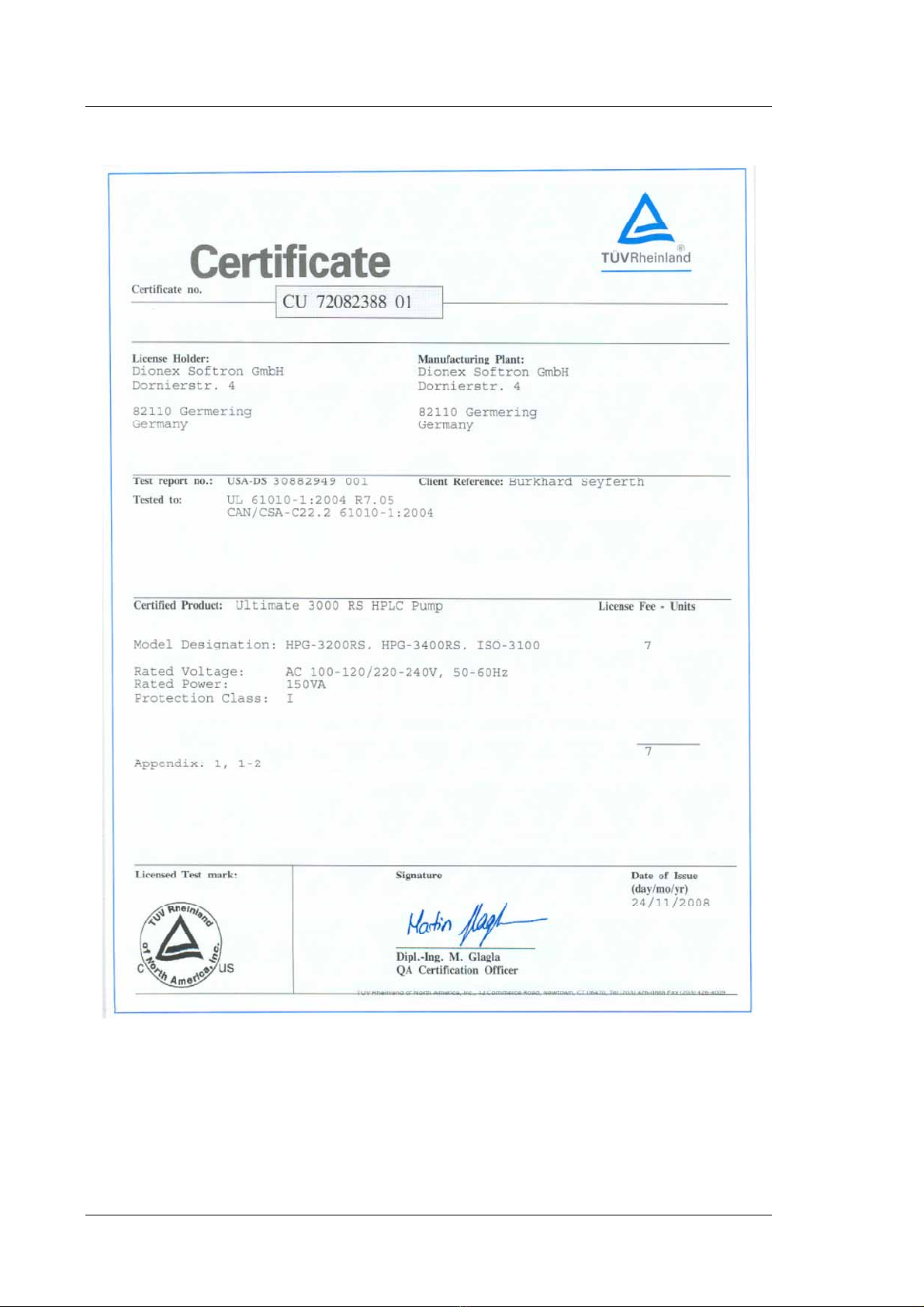
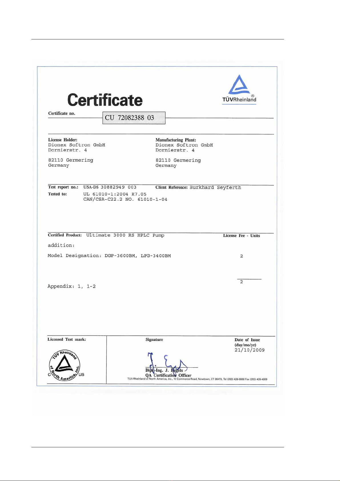
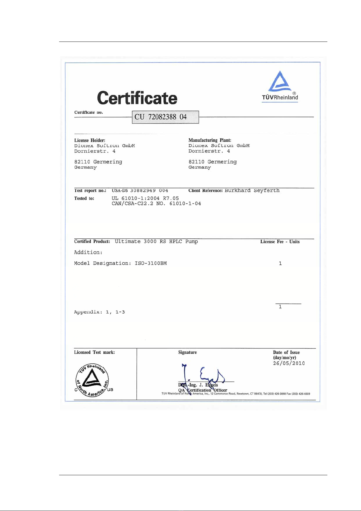
Declaration of Conformity
Product: Pump
Types: ISO-3100SD, ISO-3100BM
HPG-3200SD,HPG-3200RS, HPG-3400SD, HPG-3400RS
LPG-3400SD, LPG-3400RS, LPG-3400BM
DGP-3600SD, DGP-3600RS, DGP-3600BM
Dionex GmbH herewith declares conformity of the above products with the
respective requirements of the following regulations:
Machinery Directive 2006/42/EC
Low-Voltage Directive 2006/95/EC
EMC Directive 2004/108/EC
The safety of the machinery was evaluated based on the following standard:
EN-ISO-14121-1
Safety of machinery - risk assessment, part 1
The electrical safety of the products was evaluated based on the following
standard:
EN 61010-1: 2002
Safety requirements for electrical equipment for measurement, control and
laboratory use, Part 1: General Requirements
The Electromagnetic Compatibility (EMC) of the products was evaluated
based on the following standard:
DIN EN 61326: 2006
Electrical equipment for measurement, control and laboratory use
EMC Requirements
Person responsible for the technical CE documentation: Burkhard Seyferth
at Dionex Softron GmbH, Dornierstrasse 4, D-82110 Germering
This declaration is issued for the manufacturer
Dionex Softron GmbH
Dornierstraße 4
D-82110 Germering
by the President, Dr. Peter Jochum.
August 10, 2010
UltiMate 3000 Series:
SD, RS, and BM Pumps
Page II Operating Instructions
UltiMate 3000 Series:
SD, RS, and BM Pumps
Operating Instructions Page III
UltiMate 3000 Series:
SD, RS, and BM Pumps
Page IV Operating Instructions
UltiMate 3000 Series:
SD, RS, and BM Pumps
Operating Instructions Page V

UltiMate 3000 Series:
SD, RS, and BM Pumps
Page VI Operating Instructions

UltiMate 3000 Series:
SD, RS, and BM Pumps
Operating Instructions Page i
Table of Content
1Introduction................................................................................................................... 1
1.1 How to Use this Manual ........................................................................................ 1
1.2 Safety Information .................................................................................................2
1.2.1 Symbols on the Pump and in the Manual.........................................................2
1.2.2 General Safety Precautions............................................................................... 3
1.2.3 Consignes Générales de Sécurité...................................................................... 6
1.3 Intended Use .......................................................................................................... 9
1.4 Federal Communications Commission (FCC) Note.............................................. 9
2Overview...................................................................................................................... 11
2.1 Unit Description................................................................................................... 11
2.2 Pump Configurations ........................................................................................... 12
2.2.1 Overview ........................................................................................................ 12
2.2.2 Combinations of UltiMate 3000 Pumps and Solvent Racks .......................... 13
2.2.3 Special Information for Biocompatible Pumps .............................................. 14
2.3 Operating Principle.............................................................................................. 15
2.4 Front Panel Elements........................................................................................... 16
2.5 Rear Panel............................................................................................................ 17
2.5.1 Power Switch.................................................................................................. 18
2.5.2 Fuse Cartridge ................................................................................................ 18
2.5.3 USB Connector............................................................................................... 18
2.5.4 Digital I/O....................................................................................................... 19
2.5.5 Solvent Rack...................................................................................................19
2.6 Fluid Connections................................................................................................ 20
2.7 Rear Seal Wash System ....................................................................................... 21
2.8 Mixing System and Inline-Filter.......................................................................... 22
2.9 Purge Unit............................................................................................................ 23
2.10 Leak Sensor.......................................................................................................... 23
2.11 Vacuum Degasser ................................................................................................ 24
2.12 Pulse Damper....................................................................................................... 24
2.13 Chromeleon Software .......................................................................................... 25
2.14 Wellness, Predictive Performance and Diagnostics ............................................ 26
3Installation................................................................................................................... 27
3.1 Facility Requirements.......................................................................................... 27
3.2 Unpacking............................................................................................................ 27
3.3 Positioning the Pump in the UltiMate 3000 System............................................ 28
3.4 Connecting the Pump...........................................................................................30
3.4.1 General Information ....................................................................................... 30
3.4.2 Connecting the USB Cable............................................................................. 30

UltiMate 3000 Series:
SD, RS, and BM Pumps
Page ii Operating Instructions
3.4.3 Connecting the Power Cord............................................................................31
3.4.4 Connecting the Solvent Rack and Digital I/O ................................................31
3.5 Setting Up the Pump in Chromeleon ...................................................................32
3.5.1 Loading the USB Driver for the Pump...........................................................32
3.5.2 Installing the Pump.........................................................................................34
3.5.3 Configuring the Pump.....................................................................................35
3.5.3.1 Initial Installation.....................................................................................35
3.5.3.2 Changing the Configuration Properties ...................................................42
3.6 Connecting a Dionex ESA Detector to the Pump................................................43
4Preparation for Operation (Startup) ........................................................................45
4.1 Overview of Actions............................................................................................45
4.2 General Precautions for Connecting Capillaries..................................................47
4.3 Solvent Reservoirs ...............................................................................................48
4.3.1 General Notes .................................................................................................48
4.3.2 Connecting the Solvent Reservoirs.................................................................49
4.3.2.1 All pumps except ISO-3100BM..............................................................49
4.3.2.2 ISO-3100BM ...........................................................................................50
4.4 Setting Up the Rear Seal Wash System ...............................................................51
4.5 Connecting Drain Tubing ....................................................................................53
4.6 Purging the Pump.................................................................................................54
4.6.1 Purging the Pump Manually ...........................................................................55
4.6.2 Purging the Pump By Using the Autosampler................................................57
4.7 Equilibrating the System......................................................................................58
5Operation and Maintenance ......................................................................................61
5.1 Power-Up .............................................................................................................61
5.2 Status Screens ......................................................................................................62
5.3 Operation with Chromeleon.................................................................................64
5.3.1 Connecting to Chromeleon.............................................................................64
5.3.2 Direct Control .................................................................................................65
5.3.3 Automated Control .........................................................................................68
5.4 Function Keys and Menus on the Pump Display.................................................70
5.4.1 Showing the Function Keys............................................................................70
5.4.2 Pump Menus ...................................................................................................72
5.4.2.1 General Menu Layout and Structure .......................................................73
5.4.2.2 Main Menu ..............................................................................................74
5.4.2.3 Control Menu...........................................................................................75
5.4.2.4 Preferences Menu ....................................................................................75
5.4.2.5 Diagnostics Menu....................................................................................76
5.4.2.6 Configuration Menu ................................................................................76
5.5 Information for Operating the Pump....................................................................77
5.5.1 Choosing the Solvents ....................................................................................77
5.5.2 Linking the Pump to the Autosampler............................................................80

UltiMate 3000 Series:
SD, RS, and BM Pumps
Operating Instructions Page iii
5.5.3 Setting the Flow Rate, Flow Acceleration, and Flow Deceleration ............... 81
5.5.4 Setting the Pressure Limits.............................................................................82
5.5.5 Recording the Pump Pressure......................................................................... 83
5.5.6 Rear Seal Wash System.................................................................................. 83
5.5.6.1 Working with Rear Seal Washing........................................................... 83
5.5.6.2 Choosing the Seal-Washing Liquid......................................................... 84
5.5.6.3 What happens …. .................................................................................... 84
5.5.7 Purging the Pump ...........................................................................................85
5.5.8 Detecting Liquid Leaks in the Pump..............................................................86
5.5.9 Adjusting the Screen Brightness or Contrast.................................................. 87
5.5.10 SmartStartup and SmartShutdown..................................................................87
5.5.11 Vacuum Degasser (LPG-3400 and SRD-3x00)..............................................88
5.5.11.1 General Notes for Degasser Operation.................................................... 88
5.5.11.2 Turning the Degasser on and off ............................................................. 89
5.5.12 General Precautions for Operating an ISO-3100BM ..................................... 90
5.6 Special Chromeleon Functions............................................................................ 91
5.6.1 Predictive Performance .................................................................................. 91
5.6.2 Pump Diagnostics........................................................................................... 93
5.6.3 Setting a Gradient Curve ................................................................................ 94
5.6.4 Liquid Level Monitoring for Solvent Reservoirs and Waste Container.........94
5.6.5 Using the Digital Inputs and Outputs (Digital I/O)........................................ 96
5.6.6 Operational Qualification and Performance Qualification.............................96
5.7 Shutting Down the Pump.....................................................................................97
5.8 Routine and Preventive Maintenance ..................................................................99
6Troubleshooting ........................................................................................................ 103
6.1 Overview............................................................................................................ 103
6.2 Pump Block Status Indicator ............................................................................. 104
6.3 Messages on the Pump Display ......................................................................... 105
6.4 Chromeleon Diagnostics Messages ................................................................... 112
6.5 Operating Problems ........................................................................................... 114
6.6 Checking the Compression Values.................................................................... 121
7Service........................................................................................................................ 123
7.1 General Notes ....................................................................................................123
7.2 Eliminating Leakage.......................................................................................... 124
7.3 Rear Seal Wash System ..................................................................................... 125
7.3.1 Inspecting the Rear Seal Wash System for Leakage....................................125
7.3.2 Replacing the Peristaltic Tubing .................................................................. 126
7.3.3 Replacing the Detector .................................................................................127
7.3.4 Cleaning the Detector................................................................................... 127
7.4 Replacing the Check Valve Cartridges.............................................................. 128
7.5 Pistons and Piston Seals..................................................................................... 130
7.5.1 Visually Inspecting the Pump for Piston Seal Leakage................................134
7.5.2 Pump Head and Pistons................................................................................ 135

UltiMate 3000 Series:
SD, RS, and BM Pumps
Page iv Operating Instructions
7.5.2.1 Removing the Pump Head and Pistons..................................................135
7.5.2.2 Installing the Pistons and Pump Head ...................................................137
7.5.3 Replacing the Piston Seals............................................................................139
7.5.3.1 Disassembling the Pump Head and Removing the Piston Seals ...........140
7.5.3.2 Cleaning the Pistons ..............................................................................141
7.5.3.3 Installing the Piston Seals and Reassembling the Pump Head..............142
7.5.3.4 Recommended Actions after Piston Seal Replacement.........................144
7.5.3.5 Replacing the Piston Seals in the Plate of the Seal Wash System.........145
7.6 Mixing System...................................................................................................146
7.6.1 Capillary Mixer.............................................................................................146
7.6.2 Static Mixer ..................................................................................................147
7.6.2.1 Replacing the Static Mixer ....................................................................147
7.6.2.2 Checking the Static Mixer for Permeability..........................................148
7.7 Inline Filter.........................................................................................................149
7.7.1 Replacing the Inline Filter (ISO-3100).........................................................149
7.7.2 Inline Filter (LPG-3400BM, DGP-3600BM)...............................................150
7.7.2.1 Replacing the Inline Filter .....................................................................150
7.7.2.2 Replacing the Filter Frit in the Inline Filter...........................................151
7.7.3 Checking the Inline Filter for Permeability..................................................152
7.8 Replacing the Purge Valve Knob.......................................................................153
7.9 Testing the Pump for Leakage ...........................................................................154
7.10 Vacuum Degasser (Rinsing the Degassing Channels).......................................157
7.11 Replacing the Main Power Fuses.......................................................................158
7.12 Updating the Pump Firmware............................................................................159
8Pump-Specific Information......................................................................................161
8.1 ISO-3100............................................................................................................162
8.1.1 ISO-3100SD .................................................................................................162
8.1.1.1 Interior Components..............................................................................162
8.1.1.2 Flow Schematic .....................................................................................163
8.1.1.3 Operating Principle (Schematics)..........................................................164
8.1.2 ISO-3100BM ................................................................................................165
8.1.2.1 Interior Components..............................................................................165
8.1.2.2 Flow Path...............................................................................................166
8.1.3 Operating Principle (Schematics).................................................................167
8.2 LPG-3400...........................................................................................................168
8.2.1 Interior Components .....................................................................................168
8.2.2 Flow Path......................................................................................................169
8.2.3 Operating Principle (Schematics).................................................................171
8.3 DGP-3600 ..........................................................................................................172
8.3.1 Interior Components .....................................................................................172
8.3.2 Flow Path......................................................................................................173
8.3.3 Operating Principle (Schematics).................................................................175

UltiMate 3000 Series:
SD, RS, and BM Pumps
Operating Instructions Page v
8.4 HPG-3200 .......................................................................................................... 176
8.4.1 Interior Components..................................................................................... 176
8.4.2 Flow Path...................................................................................................... 177
8.4.3 Operating Principle (Schematics)................................................................. 178
8.5 HPG-3400 .......................................................................................................... 179
8.5.1 Interior Components..................................................................................... 179
8.5.2 Flow Path...................................................................................................... 180
8.5.3 Possible Gradient Combinations and Operating Principle (Schematics) ..... 181
9Optimizing the Pump for Specific Applications .................................................... 183
10 Technical Information.............................................................................................. 187
11 Accessories, Consumables, and Spare Parts .......................................................... 191
11.1 Standard Accessories ......................................................................................... 191
11.2 Optional Accessories .........................................................................................197
11.3 Consumables and Spare Parts............................................................................ 199
12 Reference Information ............................................................................................. 207
12.1 Chemical Resistance of PEEK........................................................................... 207
12.2 Solvent Miscibility............................................................................................. 210
12.3 Properties of Common Solvents ........................................................................ 211
12.4 Safety Information about Flammable Solvents .................................................212
13 Appendix.................................................................................................................... 215
13.1 Digital I/O (Pin Assignment)............................................................................. 215
13.2 Solvent Rack (Pin Assignment).........................................................................216
14 Index........................................................................................................................... 217

UltiMate 3000 Series:
SD, RS, and BM Pumps
Page vi Operating Instructions

UltiMate 3000 Series:
SD, RS, and BM Pumps
Operating Instructions Page 1
1 Introduction
1.1 How to Use this Manual
The layout of this manual is designed to provide quick reference to the sections of interest
to the reader. However, in order to obtain a full understanding of the pump, Dionex
recommends that you review the manual thoroughly before beginning operation.
Almost all descriptions in the manual apply to all SD, RS, and BM pumps in the UltiMate
3000 pump series. Therefore, the term "the pump" is used throughout the manual. If some
detail applies to only one pump model or version, the model (version) is identified by name. If
only the pump name is indicated, for example, HPG-3200, the related information applies to
all pump versions (that is, for the example, to the HPG-3200SD and HPG-3200RS).
The same applies to the descriptions of the Viper™ capillary connections throughout this
manual. They apply also to the nanoViper™ capillary connections if not otherwise stated.
Notes: The device configuration may vary; therefore, not all descriptions necessarily
apply to your particular pump.
The optical design of some components may differ from the representation in the
pictures in this manual, but this does not affect the descriptions.
The descriptions in this manual refer to firmware version 3.00 and Chromeleon
6.80 Service Release 10. If you want to operate the pump with Chromeleon 7,
note the information on page 25.
The information contained in this manual should not be construed as a commitment by
Dionex. Dionex assumes no responsibility for any errors that may appear in this document.
This document is believed to be complete and accurate at the time of publication. In no
event shall Dionex be liable for incidental or consequential damages in connection with or
arising from the use of this document.
The information contained in this document is subject to change without notice.
CHROMELEON®, UltiMate®, Corona®, and Coulochem®are registered trademarks of
Dionex Corporation in the United States of America and/or other countries. Viper™ and
nanoViper™ are trademarks of Dionex Corporation in the United States of America and/or
other countries. All other trade or company names mentioned are subject to the copyright and
the property and trademark rights of the respective companies.
UltiMate 3000 Series:
SD, RS, and BM Pumps
Page 2Operating Instructions
All rights reserved, including those for photomechanical reproduction and storage on
electronic media. No part of this publication may be copied or distributed, transmitted,
transcribed, stored in a retrieval system, or transmitted into any human or computer language,
in any form or by any means, electronic, mechanical, magnetic, manual, or otherwise, or
disclosed to third parties without the express written permission of Dionex.
1.2 Safety Information
The CE Mark label and cTUVus Mark safety label on the pump indicate that the pump is
compliant with the related standards (pages I and II).
1.2.1 Symbols on the Pump and in the Manual
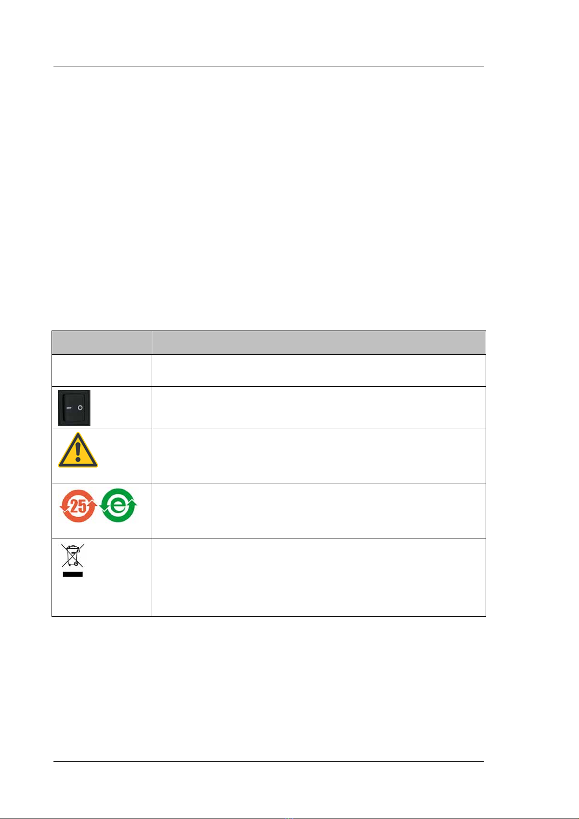
The table shows the symbols used on the pump:
Symbol Description
˜
Alternating current—Courant alternatif
Power supply is on (-)—L'instrument est mis sous tension (-) and
Power supply is off (O)—L'instrument est mis hors tension (O)
Refer to the Operating Instructions to prevent risk of harm to the operator and to
protect the instrument against damage.
Référez-vous à ce manuel pour éviter tout risque de blessure à l'opérateur et/ou
protéger l'instrument contre tout dommage.
Label according to the "Measures for Administration of the Pollution Control of
Electronic Information Products" (China RoHS) guideline
Étiquette "Measures for Administration of the Pollution Control of Electronic
Information Products" (China RoHS)
WEEE (Waste Electrical and Electronic Equipment) label—For more
information, see the WEEE Information section in the "Installation and
Qualification Documents for HPLC Systems" binder. Étiquette WEEE (Waste
Electrical and Electronic Equipment) —Pour plus d'informations, référez-vous au
chapitre WEEE Information dans le classeur "Installation and Qualification
Documents for HPLC Systems".

UltiMate 3000 Series:
SD, RS, and BM Pumps
Operating Instructions Page 3
At various points throughout the manual, messages of particular importance are indicated
by certain symbols:
Tip: Indicates general information, as well as information intended to
optimize the performance of the instrument.
Important: Indicates that failure to take note of the accompanying information
could cause wrong results or may result in damage to the module.
Important: Indique que ne pas tenir compte de l'information jointe peut conduire
à de faux résultat ou endommager l'instrument.
Warning: Indicates that failure to take note of the accompanying information
may result in personal injury.
Avertissement: Indique que ne pas tenir compte de l'information jointe peut
entraîner des blessures corporelles.
1.2.2 General Safety Precautions
When working with analytical instrumentation, you should know the potential hazards of
using chemical solvents. Wear appropriate protective clothing.
Tips: Before initial operation of the pump, make sure that you are familiar with the
contents of this manual.
Observe any warning labels on the pump and see the related sections in these
Operating Instructions.
To avoid the possibility of personal injury and damage to the instrument, observe the
following general safety precautions when operating the pump or carrying out any
maintenance work:
Install the HPLC system in a well-ventilated laboratory. If the mobile phase includes
volatile or flammable solvents, do not allow them to enter the workspace.
For minimum interference effects, all components of the analytical system should be
connected to the same mains output (same phase).
The pump is primed with 2-propanol. During initial operation of the pump, make sure that
the solvents used are miscible with 2-propanol. Otherwise, follow the appropriate
intermediate steps.
When lifting or moving the pump, always lift by the sides of the instrument. Lifting the
pump by the front panel may damage the front panel door.

UltiMate 3000 Series:
SD, RS, and BM Pumps
Page 4Operating Instructions
Do not place any heavy objects on the open front panel door. This may damage the door.
Always set a lower pressure limit for the HPLC pump. This prevents damage resulting
from leakage or from running the pump dry over a longer period. Activate liquid level
monitoring for the solvent reservoirs (page 94).
To avoid that the pressure calibration of the pump is impaired, turn on the pump only
when the pump pressure is down. To ensure that the pressure is down, open the purge
valve before turning on the pump. If you are operating an ISO-3100BM, observe the
precautions on page 90.
Never run the pump dry. Damage to the pistons or the piston seals could result.
Before you start operating the pump, check the liquid level in the wash liquid reservoir
and refill the reservoir as needed. After turning on the pump, wait until the wash liquid
has passed all pump heads.
Always use fresh rear seal wash liquid.
Dionex advises against recycling the solvents. This may impair the performance of the
seals.
When connecting the capillaries, make sure that the connectors are free from
contaminants. Even minute particles may cause damage to the system, for example, to the
column.
After operation, rinse out buffers and solutions that form peroxides.
Before switching from buffer to organic solution, rinse the pump thoroughly with
deionized water.
When switching to another solvent, ensure that the new solvent is miscible with the one
contained in the pump. Otherwise, the pump can be damaged; for example, by
flocculation.
If the pump flow is interrupted for longer periods (> 1 hour), turn off the lamps in any UV
or RF detector connected to the pump. This will prevent evaporation in the flow cell.
If you want to connect an ESA Corona or Coulochem III detector to the pump, refer to
page 43 for details.
Always use the frits recommended by Dionex to prevent particulate matters from entering
the HPLC system. Using other frits may considerably affect the system performance.
Do not use stainless steel frits with the BM pumps; this renders the biocompatibility void.
Frits are used on the drawing side (in the solvent reservoirs) and on the high-pressure side
(in the inline filter).
If the mobile phase includes volatile or flammable solvents, avoid open flames and
sparks.

UltiMate 3000 Series:
SD, RS, and BM Pumps
Operating Instructions Page 5
If a leak occurs, turn off the pump and remedy the situation immediately.
Disconnect the pump from all power sources before removing the panels. When the
panels are removed, dangerous electrical connections will be exposed. The enclosure
should be opened only by authorized service personnel.
Always replace blown fuses with original spare part fuses from Dionex (page 191).
Replace faulty power cords and communication cables.
Many organic solvents and buffers are toxic. Know the toxicological properties of all
mobile phases that you are using.
The toxicological properties of many samples may not be well known. If you have any
doubt about a sample, treat it as if it contains a potentially harmful substance.
Wear goggles when handling mobile phases or operating the pump. An eyewash facility
and a sink should be close to the unit. If any mobile phase splashes on the eyes or skin,
wash the affected area and seek medical attention.
Dispose of waste mobile phase in an environmentally safe manner that is consistent with
all local regulations. Do not allow flammable or toxic solvents to accumulate. Follow a
regulated, approved waste disposal program. Never dispose of flammable or toxic
solvents through the municipal sewage system.
Use only standard solvents (HPLC grade) and buffers that are compatible with all parts
that may be exposed to solvents.
In an UltiMate 3000 system, some components are made of PEEK™. While this polymer
has superb chemical resistance to most organic solvents, it tends to swell when in contact
with trichlormethane (CHCl3), dimethyl sulfoxide (DMSO), or tetrahydrofuran (THF). In
addition, it is attacked by concentrated acids, such as, sulfuric acid and nitric acid or a
mixture of hexane, ethyl acetate, and methanol. (Swelling or attack by concentrated acids
is not a problem with brief flushing procedures.)
Do not use PEEK tubing that is stressed, bent, or kinked.
Avoid looking directly into the pump light LED and do not use light focusing instruments
for viewing the light beam. The high luminosity of the lamp can be harmful to the eyes.
Before interrupting operation for several days or more or when preparing the pump for
transport, observe the precautions for shutting down the pump (page 97).
Use original Dionex spare parts only. Substituting non-Dionex parts or using non-Dionex
accessories may impair the performance of the instrument.
Do not use the pump in ways other than those described in these operating instructions.

UltiMate 3000 Series:
SD, RS, and BM Pumps
Page 6Operating Instructions
1.2.3 Consignes Générales de Sécurité
Veuillez noter: Avant de commencer à utiliser la pompe, assurez-vous que vous
vous êtes familiarisés avec le contenu de ce manuel.
Observez des étiquettes d'avertissement sur l'appareil et référez-vous
aux sections correspondantes dans ce mode d'emploi.
Veuillez observer les consignes générales de sécurité suivantes lorsque vous utilisez
l'instrument ou que vous procédez à des opérations de maintenance.
Installez le système HPLC dans un laboratoire bien ventilé. Si la phase mobile contient
des solvants volatils ou inflammables, empêchez qu'ils ne pénètrent dans l'espace de
travail.
Afin d'éviter au maximum les interférences, tous les éléments du système analytique
doivent être raccordés à la même ligne secteur (même phase).
La pompe est stockée sous 2-propanol. Au cours démarrage de la pompe, assurez-vous
que les solvants utilisés soient miscibles avec le 2-propanol. Sinon, suivez les étapes
intermédiaires appropriées.
Le panneau avant bascule vers le haut. Afin d'éviter d'endommager la pompe lorsque que
vous la soulevez ou la déplacez, saisissez-la toujours par les côtés de l'unité.
Ne placez aucun objet lourd sur la porte ouverte du panneau avant. Ceci pourrait
endommager la porte.
Réglez toujours une limite de pression minimum pour la pompe HPLC. Ceci prévient les
dommages résultant de fuites ou de long-terme fonctionnement à sec de la pompe.
Activez la surveillance de niveau liquide pour des réservoirs (page 94).
Afin d'éviter que le calibrage de pression de la pompe ne soit pas entravé, mettez en
marche la pompe seulement quand la pompe est sans pression. Toujours ouvrez la vis de
purge avant mettre la pompe en marche. Si la pompe est une ISO-3100BM, observez les
précautions figurant en page 90.
Ne faites jamais fonctionner la pompe à sec. Il peut en résulter des dommages aux pistons
ou aux joints de piston.
Avant de mettre en marche la pompe, assurez-vous que le réservoir de rinçage du joint
arrière est rempli. Attendez jusqu'à ce que le rinçage du joint arrière ait été pompé par
toutes les têtes de pompe.
Utilisez toujours le liquide frais pour le rinçage du joint arrière.
Dionex déconseille de recycler les solvants. Ceci peut nuire aux performances des joints.
Other manuals for UltiMate 3000 Series
1
Table of contents
Other Dionex Water Pump manuals


Popular Water Pump manuals by other brands


PSG Dover
PSG Dover WILDEN A1 Accu-Flo Engineering, operation & maintenance

Warren rupp
Warren rupp SANDPIPER EH2-M Service and operating manual

versa
versa E1 Series Service & operating manual

Kerr Pump Corporation
Kerr Pump Corporation KT-3350 Parts & service manual

Graco
Graco Fast-Ball 222104 Instructions-parts list

Fiamma
Fiamma AQUA F 13 Series Installation and usage instructions