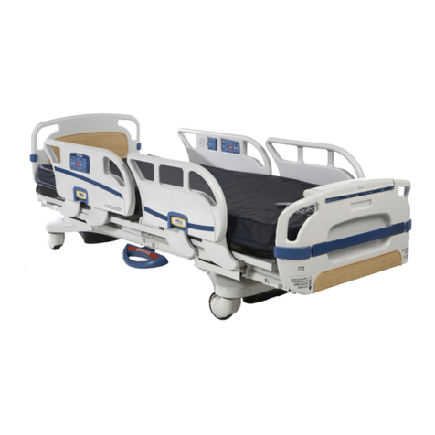
Direct Supply Panacea 1750 User manual

Please keep and refer to this Owner’s Manual.
Thank you for purchasing a Direct Supply®Panacea®1750/2000 Adjustable-Height Low Bed from
Direct Supply Equipment & Furnishings®. Please read this entire guide carefully and keep it for
future reference.This guide will provide you with instructions, warnings, warranty information and
other important information about your Direct Supply Panacea bed. Share this information with your
housekeeping, nursing and maintenance staff to help ensure the bed is cared for properly.
1-800-634-7328 ■DirectSupply.com
Direct Supply®Panacea®
1750 & 2000 Adjustable-Height Low Bed
Owner’s Manual

2
Please keep and refer to this Owner’s Manual.
Introduction
Definitions and Symbols
NOTE: Indicates a tip.
CAUTION: Indicates correct operating or maintenance procedures in order to prevent damage to or
destruction of the equipment or other property.
WARNING: Calls attention to a potential danger that requires correct procedures or practices in
order to prevent personal injury.
DEVICE: Direct Supply®Panacea®1750 or 2000 Bed.
YOU and YOUR: The facility, community or other entity that has purchased the device.
WE, US and OUR: Direct Supply Manufacturing, Inc.
• Attention. Consult accompanying drawings.
Table of Contents
Warnings ......................................................... 3-5
Environmental and Electrical Specifications .. 6
Locating Your Serial Number ....................... 6
Directions for Use......................................... 7-14
Unpacking....................................................... 7
Foot Panel Installation................................... 8
Installation of Baseboard Bumper................ 9
Installation of Mattress Stop....................... 10
I.V. Sockets ................................................... 11
Installation of Staff Control Panel .............. 12
Bed Positioning ............................................ 13
Setting Space Saving Angle (4°) Mode ..... 14
Bed Transport ............................................. 15-19
Standard Roll at Any Height Feature ......... 15
Safety Lock Feature (optional).................... 16
Panacea 2000 .............................................. 17-18
Expandable Sleep Surface .......................... 17
Panacea 2000 Manual Vascular
Leg Lift Operation ........................................ 18
Accessories and Options ................................ 18
Optional Battery ........................................... 18
Servicing...................................................... 19-21
Troubleshooting...................................... 19-20
Steps for Isolating Electrical Problems ...... 21
Cleaning............................................................ 22
Cleaning Method.......................................... 22
Cleaning Instructions................................... 22
Periodic Inspection.......................................... 22
Limited Warranty ............................................ 23
Customer Service ............................................ 24

1-800-634-7328 ■DirectSupply.com 3
Warnings
• WARNING: Possible Injury Or Death.This product is intended for use as an adjustable mattress
platform that contours for resident/patient comfort with adjustable height for resident/patient and
caregiver convenience. Use of this product in a manner for which it was not designed could result in
unproven or unsafe configuration, potentially resulting in injury or death.
• WARNING: Possible Injury. Before adjusting bed, ensure that area under and near bed perimeter is
free of people and obstructions. Failure to do so could result in injury or damage to the bed.
• WARNING: Possible Injury. Keep bed in lowest position except when providing care (bathing,
clothing changes, etc.). Bed should be at lowest convenient height for entry or exit. Failure to do so
could result in injury.
• WARNING: Possible Injury Or Death. Resident/ patients may become entangled in pendant cord.
Resident/patients with reduced mental acuity should not be allowed access to pendant. Unsupervised
use of pendant could result in injury or death.
• WARNING: Possible Injury Or Death. Bed safe working load is 500 pounds.This is total weight
counting resident/patient, mattress, bedding accessories and any other equipment or persons likely to
be on bed. Do not exceed 500-pound safe working load. Exceeding the safe working load could result
in property damage, injury or death.
• WARNING: Possible Injury Or Death. Do not roll bed over abrupt thresholds with resident/patient
in bed. Bed is not designed for transporting resident/patient. Transporting resident/patient in the bed
could result in injury or death.
• WARNING: Possible fire hazard when used with oxygen administrating equipment other than nasal,
mask or ½ bed length tent type. Not for use with full bed length tent or hyperbaric oxygen chamber.
Oxygen tent should not extend below mattress support platform. Lock hand control at foot of bed
when using oxygen administering equipment.
• WARNING: Possible Shock Hazard. Unplug power cord from wall outlet before performing any
maintenance, cleaning or service to the bed. Failure to do so could result in injury or death. Note: In
case of unexpected movement, unplug bed from any outlet.
• WARNING: Possible Shock Hazard. Injury may result from improper routing of the power cord.
Always follow the proper factory-installed routing configuration. Failure to do so could result in injury
or death.
• WARNING: Possible Injury Or Death. Use a mattress that is properly sized to fit mattress deck,
that will remain centered on mattress deck relative to State and Federal guidelines. Direct Supply
recommends the use of a mattress with minimum dimensions of 35 inches wide and 6 inches deep.
Length should match mattress support platform. Use of an improperly fitted mattress could result in
injury or death. If using the optional width extension kit, or the bed is equipped with the integrated
width expansion, Direct Supply recommends the use of a mattress with a minimum width of 39 inches
for a 39 inch setting and 42 inches for 42 inch setting.

4
Warnings (cont.)
• WARNING: Possible Injury Or Death. If a resident/patient’s mental or physical condition could lead
to resident/patient entrapment, the mattress support platform should be left in the flat position when
unattended. Failure to do so could result in injury or death.
• WARNING: An optimal bed system assessment should be conducted on each resident by a
qualified clinician or medical provider to ensure maximum safety of the resident.The assessment
should be conducted within the context of, and in compliance with, the state and federal guidelines
related to the use of restraints and bed system entrapment guidance, including the Clinical
Guidance for the Assessment and Implementation of Side Rails published by the Hospital Bed
Safety Workgroup of the U.S. Food and Drug Administration. Further information can be obtained
at the following web address: http://www.fda.gov/MedicalDevices/ProductsandMedicalProcedures/
GeneralHospitalDevicesandSupplies/HospitalBeds/default.htm.
• WARNING: Possible Injury Or Death. Use a properly sized mattress in order to minimize the gap
between the side of mattress and assist device.This gap must be small enough to prevent resident/
patient from getting his/her head or neck caught in this location. Make sure that raising or lowering
bed, or contouring the sleep surface, does not create any hazardous gaps. Excessive gaps may result
in injury or death.
• WARNING: Possible Injury Or Death. Locate mounting brackets for assist devices strictly according
to instructions. Gap between head/foot panel and assist device must be small enough or large enough
to prevent resident/patient from getting his/her head or neck caught in this location (see specific Assist
Device Installation Instructions for more information). If multiple assist devices are used, position
each so that gap between them is large enough for trunk and hips to pass through easily. Make sure
raising or lowering bed, or contouring sleep surface does not create any hazardous gaps. Failure to do
so could result in injury or death. Important Note: Powered air mattress surfaces may pose a risk of
entrapment. Prior to use, ensure the therapeutic benefits outweigh the risk of entrapment.
• WARNING: Possible Injury Or Death. Do not use an assist device if any openings within assist
device body allow resident/patient to get his/her head or neck lodged within these openings. Use of
assist devices with large openings may result in injury or death.
• WARNING: Possible Injury Or Death. Do not use any Panacea®assist device until you verify it is
designed specifically for you Panacea®bed and it is locked in place. Failure to lock assist devices may
result in injury or death.
• WARNING: Possible Injury Or Death. Do not use any replacement parts not manufactured,
marketed or provided by Direct Supply Panacea on any Direct Supply Panacea bed. Use of unapproved
replacement parts may result in injury or death.
• WARNING: Possible Injury Or Death. If using accessories not manufactured, marketed or provided
by Direct Supply Panacea for Direct Supply Panacea beds, consult with the manufacturer for
compatibility and limitations prior to use. Failure to do so may result in injury or death.
• WARNING: Possible Shock Hazard. If the bed power cord has a hospital-grade, 3-prong grounding
plug, grounding reliability can only be achieved when equipment is connected to an equivalent
receptacle marked hospital-grade.

1-800-634-7328 ■DirectSupply.com 5
• WARNING: Possible Injury. Sitting on or sliding over the Mattress Side Stop can cause skin injury if
the bed mattress compresses to less than 1.5 inches under user’s weight.
• WARNING: Possible Injury. Risk of entanglement or injury may occur if mattress used with Mattress
Side Stop does not fill the entire width between stops or which compresses to less than 1.5 inches
under user’s weight.
• WARNING: Possible Injury or Death. Floor locks increase bed stability and resident safety. Make
sure the bed is in a locked position with respect to the floor by ensuring the casters are off the floor or
if equipped, the safety lock is in the locked position before attempting any resident transfers. Failure to
do so could result in injury or death.
• WARNING: Possible Injury. Use caution when activating the safety lock function.This feature was
designed to be activated by your foot. Using your hand to activate the safety lock system could result
in injury.
• CAUTION: In the absence of line voltage, all bed adjustments can be achieved via an externally
available backup battery. Direct Supply recommends a minimum of one battery for every twenty five
beds per facility.
• CAUTION:This device complies with EMC requirements of IEC 60601-1-2. Radio transmitting
equipment, cellular phones or similar electronic devices, used in proximity of bed, may affect
bed performance.
• CAUTION: Particular precaution must be considered during exposure to strong emission sources
such as High Frequency surgical equipment and similar devices. Do not route High Frequency cables
on or near device. If in doubt, contact a qualified technician.
• CAUTION:Your Panacea bed is intended for use within an institutional healthcare environment (ie:
skilled nursing, transitional care, rehabilitational care, assisted living). Direct Supply recommends
compliance to the regulations and guidelines specified to your locality.
This product is only one part of your healthcare bed system. Proper combinations of mattress, head/
foot panels and assist devices are needed to minimize the risk of entrapment. For more information,
call Direct Supply, 800-634-7328.

6
Locating Your Product ID Label and Serial Number
The product ID label (pictured below) is located at the foot end of the bed frame, under the mattress
support deck. The serial number is located on an additional label, next to the product ID label.
Environmental and
Electrical Specifications
Standard Features
80" Mattress Support Platform
81⁄4" to 27"Travel
Quiet DC Actuators
WeldedTubular Frame
Grid Sleep Surface
Wide Stable Base
Baseboard Bumper
Heavy-Duty Casters
Mattress Stops
Electrical Specifications
Power: 120V
Frequency: 60 Hz
Current Rating: 2.0 Amps
Classification: Class I,Type B
Mode of Operation: 10% Maximum Duty Cycle
2 minutes on/18 minutes off
Circuit Protection: Auto reset current sensors
I.D. Label Symbol Definition
Attention, Consult Accompanying Documents
Safe Working Load
Type B Applied Parts
Class II Equipment
Protective Earth (ground)
Environmental Conditions
Operating Conditions:
AmbientTemperature: +50°F to +104°F
Relative Humidity: 30% to 75%
Non-Condensing
Atmospheric Pressure: 700 hPa to 1060 hPa
Protected Against Splashing Water IPX4
Storage and Shipping Conditions:
AmbientTemperature: -40°F to +158°F
Relative Humidity: 10% to 100%
Atmospheric Pressure: 500 hPa to 1060 hPa
Mechanical Specifications
Description: Dimensions:
80" Model 841⁄4"L x 35"W x 81⁄4"H
Weight
Standard: 200 lbs.
w/ Safety Lock: 210 lbs.
w/ Width Kit: Adds 40 lbs.
Maximum Back Angle 65° to horizontal
Maximum Knee Angle 35° to horizontal
Maximum Knee to Leg Angle 45°
Maximum Height Mattress
Support Platform 27" Above Floor
Minimum Height Mattress
Support Platform 81⁄4" Above Floor
Safe Working Load 500 lbs.

1-800-634-7328 ■DirectSupply.com 7
Directions for Use
Unpacking
NOTE: Unpack the bed in an area with sufficient room to work. Do not allow residents near the
bed until it has been completely set up and the work area has been cleared of all debris.
1. Inspect the bed for shipping damage. If the bed is damaged, DO NOT USE BED and
immediately contact Direct Supply Equipment & Furnishings®for further instruction.
2. Verify the proper bed model and size was shipped. If you feel there was a mistake,
DO NOT USE BED and immediately contact Direct Supply Equipment & Furnishings.
3. Carefully remove the orange packaging zip ties before operating the bed.
Assembly
Installation Of Head and Foot Panels
Tools Required: #2 Phillips Screwdriver
Head Panel Installation:
1. Locate the head panel; the head panel has a label
on the back.
2. Lay panel on a flat soft surface, face down –
threaded t-nuts facing away from the bed occupant.
3. Head panel brackets have rubber bumpers
mounted on them.
4. The panel brackets are right-left oriented. Items
welded to the side of the panel mounting tube
should be placed to the inside (Figure 1). Install
head panel brackets with four screws provided. Do
not tighten at this time.
5. Insert the brackets into the bed frame sockets
(Figure 2); maintain support of the bed panel. Insert
the safety pins on each side and latch them (Figure 3).
6. Press the mounting bracket against the bed
frame and tighten the mounting screws; right
and left side.
Figure 1
Figure 2
Figure 3

8
Foot Panel Installation:
1. Locate the Foot Panel; the foot panel does not have a label on the back.
2. Lay panel on a flat soft surface - face down – threaded t-nuts facing towards the bed occupant.
3. The panel brackets are right-left oriented. Items welded to the side of the panel mounting tube
should be placed to the inside (Figure 4). Install foot panel brackets with four screws provided.
Do not tighten at this time.
4. Insert the brackets into the bed sockets (Figure 5); maintain support of the bed panel. Insert the
safety pins on each side and latch them (Figure 6).
5. Press the mounting bracket against the bed frame and tighten the mounting screws; right and
left side.
Directions for Use (cont.)
Figure 4 Figure 5
Figure 6

1-800-634-7328 ■DirectSupply.com 9
Figure 8
Figure 7
Installation of Baseboard Bumper
Recommended Tool: Rubber Mallet
The bed will ship with two baseboard bumpers. One bumper is to be used to set the bed safely
apart from the wall if the bed were to be set in the Trendelenburg position; the appropriate
bumper will have a label attached that has 12° printed on it. The second bumper may be used as
a space-saving solution within smaller rooms.
Mode 1: Trendelenburg angle (~12° - Head End of bed lower than Foot End):
1. Place the longer baseboard bumper (12° label attached) as shown (Figure 7).
2. Tap into place with a rubber mallet or press firmly with the sole of your shoe until it locks into
place as shown (Figure 8).
Mode 2: Space saving solution angle (~4° - Head End of bed lower than Foot End):
1. Place the shorter baseboard bumper as shown (Figure 7).
2. Tap into place with a rubber mallet or press firmly with the sole of your shoe until it locks into
place as shown (Figure 8).
3. See section “Setting Space-Saving Angle (4°) Mode” following the installation of the Staff
Control pg 14.

10
Installation of Mattress Stop
The mattress stops are designed to help keep the mattress from sliding laterally or
longitudinally on the mattress support platform.
Installation Steps
Required Tool: #2 Phillips screwdriver
1. Remove the mattress stop retaining screws [4 – one in each corner of the bed’s
mattress support platform] (Figure 9). Do not discard the screws.
2. Insert the mattress stop wire-form in the hole provided (Figure 10).
3. Install and tighten the mattress stop screw (Figure 11).
4. Repeat the process for each corner.
Directions for Use (cont.)
Figure 10Figure 9
Figure 11

1-800-634-7328 ■DirectSupply.com 11
I.V. Sockets
The Direct Supply Panacea 1750 Bed Platform has four I.V. sockets as standard
equipment.There are two sockets at head end of bed and two at foot end (Figures 12 & 13).
The I.V. sockets are used with Panacea I.V. poles and most ½" I.V. poles.
Figure 12
Figure 13

12
Installation of Staff Control Panel
(Optional)
1. Mount the foot panel on the bed as indicated in previous instructions.
2. Align and insert the staff control cable plug into the cable jack, located on the bed
(Figure 14).
3. Ensure that the cable plug is fully inserted into the cable jack.
4. To secure flip the cable retaining latch (Figure 15).
Directions for Use (cont.)
Figure 14
Figure 15

1-800-634-7328 ■DirectSupply.com 13
Bed Positioning
Bed functions are operated with a 10-button pendant. Button functions on the handheld pendant
control are clearly identified with universal icons. PRIOR TO RAISING OR LOWERING THE BED AND/OR
SIDERAILS, CHECK TO ENSURE THAT THE CORD FOR THE PENDANT CONTROL HAS NOT BECOME
ENTANGLED IN BED PARTS. THE CORD SHOULD BE KEPT CLEAR OF MOVING PARTS AT ALL TIMES.
Back Operation
1. Push button to raise Back
2. Push button to lower Back
Knee Operation
3. Push button to raise Knee
4. Push button to lower Knee
AutoContour
5. Push button to raise Back & Knee
6. Push button to lower Back & Knee
Bed Height Operation
7. Push button to raise Bed
8. Push button to lower Bed
Advanced Position
9. Comfort Chair position
10. Transfer Height position
Back Operation
1. Push button to raise Back
2. Push button to lower Back
A. Back Lockout
Knee Operation
3. Push button to raise Knee
4. Push button to lower Knee
B. Knee Lockout
AutoContour
5. Push button to raise Back & Knee
6. Push button to lower Back & Knee
Bed Height Operation
7. Push button to raise Bed
8. Push button to lower Bed
C. Bed Height Lockout
Medical Position
9. ReverseTrendelenburg
10. Trendelenburg
C. Medical Position Lockout
Pendant Operation
Staff Control Operation
1 2
3 4
5 6
7 8
910
1 3 5 7 9
2 4 6 8 10
A B C

14
Setting Space-Saving Angle (4°) Mode
The bed will ship set to the Trendelenburg (12°) Mode. To change the mode to the Space-Saving
Angle (4°) Mode complete the following steps.
1. Complete the installation of the Staff Control from installation steps.
2. Simultaneously press and hold Trendelenburg and Reverse Trendelenburg function (see page 13
Staff Control Operation illustration - buttons 9 and 10) for 5 seconds on the Staff Control panel.
3. Trendelenburg / Reverse Trendelenburg lock icon will begin flashing, indicating that the system
is in a mode changing operation.
4. Press bed height down function (button 8) to select the space saving angle (4°) mode.
5. The Trendelenburg / Reverse Trendelenburg lock out icon will flash once confirming that the
desired mode has been selected.
6. To return to the bed angle to Trendelenburg (12°) mode, repeat steps 2 and 3, then press bed
height up function (button 7). The Trendelenburg / Reverse Trendelenburg lock out icon will
flash twice confirming that the increased angle (12°) mode has been selected.
• CAUTION:
Failure to install the correct baseboard bumper may result in damage to the bed and/or walls. The
baseboard bumper with the 12° label needs to be installed when in the Trendelenburg (12°) mode.
Directions for Use (cont.)

1-800-634-7328 ■DirectSupply.com 15
Bed Transport
Standard Roll-at-Any-Height Feature –
The bed features a rolling base that allows it to be rolled or locked at any bed height. In order to lock
the bed, engage the steering locks located on the casters at the head of the bed, then engage the
caster locks at all four corners of the bed. To roll the bed, disengage the caster locks; the steering
locks may remain in place for desired maneuverability.
Head-End Caster Arrangement Foot-End Caster Arrangement
1. To better steer the bed during movement, lower the caster steering brackets at the head of the bed
(Figure 16).
2. To keep the bed from moving when in the raised position, engage the caster locks at the head and
foot end on all four casters (Figure 17). Also engage the caster steering brackets (Figure 16).
• WARNINGS:
• Caster locks increase bed stability and resident safety. Caster swivel locks must be locked prior to any
resident transfer or resident use of the bed. Failure to do so could result in injury or death.
• Caster locks are not intended for use on a sloping floor or building access ramp. Use of caster locks
on a sloping floor or building access ramp could result in injury or death.
• Caster locks should be locked at all times except when the bed is being moved.
Figure 16 Figure 17

16
Safety Lock Feature (optional) –
The bed features a rolling base that allows it to be rolled or locked at any bed height. In order to lock
the bed engage the steering locks, located on the dual wheel casters at the head of the bed, then
engage the safety lock at the foot end of the bed by pressing down on the red pedal. To roll the bed
disengage the safety lock by pressing down on the green pedal. The steering locks may remain in
place for desired maneuverability.
• CAUTION: Be careful not to damage power cord when moving or placing bed. After placing bed in
service, monitor power cord positioning carefully to prevent damage as you fully operate all bed functions.
• CAUTION: When power cord is not plugged into a wall outlet, place it on sleep surface to prevent it
from contacting floor.This will help prevent cord damage when transporting bed.
• WARNING: If a power cord is damaged, remove bed from service until repairs are performed.
• WARNING: Involuntary bed movement may take place if the bed casters or safety lock are left
unlocked. Involuntary bed movement may lead to property damage or resident injury. Never leave a
bed unattended while the casters are unlocked.
• CAUTION: Moving the bed while the casters are locked may cause damage to the bed. Do not
move the bed until the casters are unlocked.
Head-End Caster Arrangement Foot-End Caster Arrangement
Figure 18 Figure 19
Bed Transport (cont.)

1-800-634-7328 ■DirectSupply.com 17
Panacea 2000 with Expandable Sleep Surface
The expandable width feature allows the mattress sleep
surface to be set at a bed width of 35", 39" or 42".
Operation of this feature:
1. If applicable, remove the sleep surface.
2. Locate the width expansion locking pin on any of the six
sleep surface extensions (Figure 20).
3. Turn the locking pin in an orientation that allows it to
be vertically lifted and removed (Figure 21).
4. Slide the sleep surface extension to the desired width.
Note the width indicator found on the head and foot
extensions (Figure 22 and 23).
5. Insert the locking pin and rotate to retain (Figure 21 and
20, respectively). Push and pull on the sleep surface
extension to ensure it is secured.
6. Repeat the above steps on the remaining sleep
surface extensions.
• WARNING: Possible Injury or Death. Use a mattress
that is properly sized to fit mattress deck, that will remain
centered on mattress deck relative to State and Federal
guidelines. Direct Supply Healthcare recommends the use
of a mattress with minimum dimensions of 35" wide and
6" deep. Length should match mattress support platform.
Use of an improperly fitted mattress could result in injury
or death if using width expansion accessory or if the bed is
equipped with expandable width. Direct Supply recommends
the use of a mattress with a minimum width of 39 inches for
a 39 inch setting and 42 inches for 42 inch setting.
• WARNING: Possible Injury or Death. Do not apply any
width expansion accessory kit to a Panacea 2000 bed.
Failure to comply may cause the bed to become unstable,
leading to a possible injury or equipment failure.
Figure 21
Figure 22
Figure 23Figure 20
Panacea 2000

18
Panacea 2000 Manual Vascular Leg Lift Operation
1. To raise: Grasp the bed’s foot deck and raise to the desired position (Figure 24)
2. To lower: Grasp the foot end of the bed’s deck and raise 1⁄2inch to 3⁄4inch above present notch,
then lower gently;
3. Or, grasp the foot end of the bed deck, raise to the highest position and lower gently.
Accessories and Options
Figure 25
Optional Battery Backup Your Panacea 1750/2000
may be equipped with a battery backup (Figure 25).
The battery will not be connected to the control box for
safe shipment. Remove the control box cover (Figure
29). Remove the soft rubber plug (Figure 26). Locate the
battery connector, route the cable under the tube between
the control box and battery, and insert it into the battery
port (Figure 27). Replace the control box cover and
snap into place. To ensure the battery has a full charge
following delivery, connect the bed to the facilities 120V
power supply for at least 24 hours prior to emergency
use. The battery continually charges whenever the bed is
connected to a 120V power supply, ensuring the system is
ready to perform during a power failure or when the bed
is disconnected from facility power.
The battery should have a useful life of 2 years,
depending upon care and usage. It is recommended to
keep the battery fully charged to provide the longest life.
If the bed is to be stored for any length of time it is a
good practice to regularly plug the bed in for 24 hours
every two months to recharge the battery.
Figure 24

1-800-634-7328 ■DirectSupply.com 19
Troubleshooting
Symptom Possible Cause(s) Action
No Power 1. Bed is not plugged into
A/C power
2. Cut/damaged power cord
3. Loose plug for pendant. Cut/
damaged pendant cord
4. Power cord not connected to
control box
5. Thermal fuse in control box has
tripped
1. Check power cord connection to
receptacle.
2. Check power cord for damage.
3. Check pendant cord
for damage.
4. Check power cord connection to
control box.
Inspect power cord for damage
5. The automatic resettable thermal
fuse will restore normal power
when a safe temperature is
reached. The time to reset may
be 10 to 15 minutes.
Ensure that the bed is operating
within the appropriate
environmental conditions, as
listed on page 6 of this manual.
Check for any obstructions that
may have hindered the bed’s
ability to move freely. Remove
obstructions as necessary.
Actuators operate,
but the wrong
movement occurs
1. Cut/damaged pendant cord
2. Actuators are plugged into the
wrong ports on the control box
1. Inspect pendant cord
for damage.
2. See control box socket
identification showing port/
socket locations.
One or more
actuators do
not function
1. Loose or unplugged connection
of actuator cord to control box
2. Cut/damaged actuator cord
3. Defective actuator
4. Defective control box
5. Check for obstructions
1. Check actuator plug to
control box.
2. Inspect actuator cord
for damage.
3. Replace actuator.
4. Replace control box.
5. Remove obstructions.
Bed is not level
when operating
Hi/Lo functions
1. Bed bumped a wall or
encountered other
obstruction causing
misalignment of actuators
2. Bed repeatedly being operated in
the mid-range loaded at one end
1. Run bed to full up or full
down position after removal of
obstructions.
2. Run bed to full up or full
down position.
Servicing

20
Servicing (cont.)
• WARNING: Possible shock hazard. Unplug
power cord from wall outlet before performing any
maintenance or service to control box and disconnect
backup battery if so equipped.
Power Cord
Conduct a yearly inspection of power cord to ensure
efficient bed operation.
1. Check power cord to make sure it has not been
damaged. If power cord needs replacement due to
damage, remove bed from service until power cord has
been replaced.
Actuator and Control Box Information
Cable and Port Identification (Figure 28)
1. Back Actuator (red)
2. Foot Actuator (green)
3. Hi-Lo Actuator (yellow)
4. Hi-Lo Actuator (yellow)
NOTE:The actuators and control box contain no
serviceable parts. Overload protection is achieved via
current-sensing technology, which will automatically reset.
If any bed function fails to operate, check to see if bed is
overloaded or constrained from movement.
To Remove Control Box
1. Raise the back section and secure.
2. Remove the cable cover by inserting a flat screwdriver
to release the locking tabs (Figure 29).
3. Slide the control box cover to reveal the cables.
4. Plugs and ports are color-coded so they can be
easily reinstalled later (See Actuator And Control
Box Information).
5. Unplug all actuator cables and pendant/staff control plug.
6. Remove (4) fasteners from control box beneath control
mounting plate.
7. Remove the ground wire.
8. To replace control box, reverse these instructions.
Actuator and Control Box Troubleshooting
Any loss of electrical function should be investigated with
the following steps:
1. Make sure that all cables are plugged in, including
pendant, staff control cables and AC power cord.
2. Switch pendant with a new one or one from a bed that
is functioning normally.
3. If these steps fail to resolve the problem, please contact
Direct Supply Equipment & Furnishings at 1-800-634-7328.
Figure 26
Figure 27
Figure 28
Figure 29
This manual suits for next models
1
Table of contents
Other Direct Supply Panacea Medical Equipment manuals
Popular Medical Equipment manuals by other brands
COOK Medical
COOK Medical FLOW J manual

C-Pro Direct
C-Pro Direct DORSIRAMP Instructions for use
Graham Field
Graham Field LUMEX TENDERCLOUD AQTC8035 Installation & operation instructions
Atmos
Atmos Variotherm operating instructions

Dräger
Dräger caleo Instructions for use
Reison
Reison nordiska 10-448 user manual
