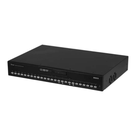
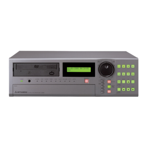
Direct DVR4090N Assembly instructions

H.264 4/8/16-Channel Networkable DVRs
Installation and Setup Guide
Products: DVR4090N, DVR8090N, DVR1690N
DVR4090N 4-Channel DVR
DVR8090N 8-Channel and DVR1690N 16-Channel DVRs
PLEASE READ THIS MANUAL BEFORE USING YOUR SYSTEM, and always follow the
instructions for safety and proper use. Save this manual for future reference.
SCD_DVRXX90N_RM
1/20/2012

ii www.SecurityCamerasDirect.com
Revision History
Date Reason for Change
1/12/2012 Initial release.
1/20/2012 Includes specic information about sensor, alarm and RS422/485 terminations.
CAUTION
Operate this system only in environments where the temperature and humidity is within the recommended range.
Operation in temperatures or at humidity levels outside the recommended range may cause electric shock and shorten the
life of the product. Refer to the specications for each system component for more information.
LEGAL NOTICE
Security Cameras Direct products are designed to meet safety and performance standards with the use of specic
Security Cameras Direct authorized accessories. Security Cameras Direct disclaims liability associated with the use
of non-Security Cameras Direct authorized accessories.
The recording, transmission, or broadcast of any person’s voice without their consent or a court order is strictly
prohibited by law.
Security Cameras Direct makes no representations concerning the legality of certain product applications such
as the making, transmission, or recording of video and/or audio signals of others without their knowledge and/or
consent. We encourage you to check and comply with all applicable local, state, and federal laws and regulations
before engaging in any form of surveillance or any transmission of radio frequencies.
Microsoft, Windows, and Internet Explorer are either registered trademarks or trademarks of Microsoft Corporation in
the United States and/or other countries. Android is a trademark of Google Inc. Use of this trademark is subject to
Google Permissions. Apple, iPhone, iPod touch, and iPad are registered trademarks of Apple Inc.
Other trademarks and trade names may be used in this document to refer to either the entities claiming the marks
and names or their products. Security Cameras Direct disclaims any proprietary interest in trademarks and trade
names other than its own.
No part of this document may be reproduced or distributed in any form or by any means without the express written
permission of Security Cameras Direct
© 2012 Security Cameras Direct. All rights reserved.
Security Cameras Direct
1 Security Cameras Direct Way, Luling, TX 78648
Sales/Support: 1.800.316.6027 | Fax: 1.830.875.9010

iii
H.264 4/8/16-Channel Networkable DVRs
Table of Contents
SECTION 1 Systems Overview ...................................................................1
1.1 About this document .................................................................1
1.2 What’s in the box ....................................................................1
SECTION 2 Installing Your System ...............................................................4
2.1 Some guidelines for camera installation .................................................4
2.2 DVR installation .....................................................................5
2.2.1 DVR placement ..................................................................5
2.2.2 Controls and connectors (DVR4090N) ...............................................6
2.2.3 Controls and connectors (DVR8090N, DVR1690N) . . . . . . . . . . . . . . . . . . . . . . . . . . . . . . . . . . . . .8
2.3 Connecting the system together. . . . . . . . . . . . . . . . . . . . . . . . . . . . . . . . . . . . . . . . . . . . . . . . . . . . . . .11
2.3.1 Connect alarm in, alarm out, PTZ devices . . . . . . . . . . . . . . . . . . . . . . . . . . . . . . . . . . . . . . . . . . .12
2.4 Install and setup a monitor ...........................................................13
2.5 Install a mouse, cameras, etc. .........................................................13
2.6 Adjusting the camera ................................................................14
2.7 Using the remote control and mouse ...................................................14
SECTION 3 DVR Setup ........................................................................17
3.1 Login to the DVR ...................................................................17
3.2 Conguring the system ..............................................................18
3.2.1 Setting the screen language and video system format . . . . . . . . . . . . . . . . . . . . . . . . . . . . . . . .19
3.2.1 Setting the system time .........................................................19
3.2.2 Change the Admin and user1 passwords . . . . . . . . . . . . . . . . . . . . . . . . . . . . . . . . . . . . . . . . . . .21
3.2.3 Add users to the system .........................................................22
3.2.4 Set HDD overwrite option ........................................................23
3.3 Record conguration settings .........................................................24
3.4 Video conguration settings ..........................................................26
3.4.1 Video setup ....................................................................27
3.4.2 AUDIO ........................................................................29
3.5 Network conguration settings .......................................................30
3.6 Alarm conguration settings .........................................................30
3.6.1 Motion detection setup .........................................................31
SECTION 4 Networking Your DVR ...............................................................34
4.1 Congure the DVR for access on your home network. . . . . . . . . . . . . . . . . . . . . . . . . . . . . . . . . . . . . .35
4.1.1 Verify local network connectability with IE . . . . . . . . . . . . . . . . . . . . . . . . . . . . . . . . . . . . . . . . .40
4.2 Accessing your DVR from the Internet ..................................................44

iv www.SecurityCamerasDirect.com
TABLE OF CONTENTS
SECTION 5 Accessing Your DVR With a Web Browser . . . . . . . . . . . . . . . . . . . . . . . . . . . . . . . . . . . . . . . . . . . . . . . 46
5.1 Connecting to your DVR with IE .......................................................46
5.2 Live screen .........................................................................47
5.3 Replay window .....................................................................48
5.4 Remote window ....................................................................48
5.5 Local setting .......................................................................49
5.6 Logout ............................................................................50
SECTION 6 KWeye Smartphone App ............................................................51
6.1 Installing KWeye ....................................................................51
6.1.1 Installing KWeye in iPhone .....................................................51
6.1.2 Installing KWeye in Android .....................................................53
6.2 Set up access to a DVR ...............................................................53
6.3 Using KWeye .......................................................................54
SECTION 7 DVR System Menus .................................................................56
7.1 Menu tree .........................................................................56
7.1.1 Tool Bar .......................................................................57
7.1.2 Menu options ..................................................................58
7.2 System menu. . . . . . . . . . . . . . . . . . . . . . . . . . . . . . . . . . . . . . . . . . . . . . . . . . . . . . . . . . . . . . . . . . . . . . .59
7.2.1 Language .....................................................................59
7.2.2 Video System ..................................................................59
7.2.3 Time Setup ....................................................................59
7.2.4 User management ..............................................................60
7.2.5 VOLUME .......................................................................63
7.2.6 HDD ..........................................................................63
7.2.7 Maintenance ...................................................................64
7.2.8 Information. . . . . . . . . . . . . . . . . . . . . . . . . . . . . . . . . . . . . . . . . . . . . . . . . . . . . . . . . . . . . . . . . . . .65
7.3 Record ............................................................................65
7.3.1 Record Channel ................................................................66
7.3.2 Record ........................................................................66
7.3.3 Bit-rate .......................................................................66
7.3.4 Resolution ....................................................................66
7.3.5 Frame Rate ....................................................................66
7.3.6 Audio .........................................................................67
7.3.7 Packtime ......................................................................67
7.3.8 Record Mode ...................................................................67

v
H.264 4/8/16-Channel Networkable DVRs
7.4 Video .............................................................................68
7.4.1 Video Channel .................................................................68
7.4.2 Name .........................................................................68
7.4.3 Position .......................................................................69
7.4.4 Live ..........................................................................69
7.4.5 Audio .........................................................................69
7.4.6 Color .........................................................................69
7.4.7 Record Time ...................................................................69
7.4.8 Margin ........................................................................69
7.4.9 Video Setup ...................................................................70
7.5 Network ...........................................................................70
7.5.1 Network Setup .................................................................71
7.5.2 DDNS Setup. . . . . . . . . . . . . . . . . . . . . . . . . . . . . . . . . . . . . . . . . . . . . . . . . . . . . . . . . . . . . . . . . . . .73
7.5.3 Email Setup ....................................................................73
7.5.4 Mobile Monitor ................................................................74
7.6 Alarm .............................................................................75
7.6.1 OUTPUT .......................................................................75
7.6.2 DURATION .....................................................................75
7.6.3 BUZZER .......................................................................75
7.6.4 PRERECORD ....................................................................75
7.6.5 EXCEPTION ....................................................................76
7.6.6 I/O Alarm ......................................................................76
7.6.7 Motion Detection ...............................................................77
7.7 PTZ ...............................................................................78
7.7.1 Channel .......................................................................79
7.7.2 Protocol .......................................................................79
7.7.3 Baud Rate .....................................................................79
7.7.4 Data Bit .......................................................................79
7.7.5 Stop Bit .......................................................................79
7.7.6 Parity .........................................................................79
7.7.7 Address .......................................................................79
SECTION 8 Cleaning ..........................................................................80
APPENDIX A O-loaded Video Files ..............................................................81
APPENDIX B Troubleshooting ...................................................................82
APPENDIX C DVR Compatible HDDs ..............................................................86
APPENDIX D DVR Compatible USB DVD Recorders ..................................................87
TABLE OF CONTENTS

vi www.SecurityCamerasDirect.com

1
H.264 4/8/16-Channel Networkable DVRs
SECTION 1: SYSTEM OVERVIEW
SECTION 1
Systems Overview
Congratulations on purchasing your H.264 Networkable Digital Video Recorder (DVR)! Your new DVR features:
• State-of-the-art H.264 compression technology to maximize your recording time and optimize your video quality. H.264
compression saves hard drive space and supports faster data transfer.
• Triplex operation, allowing you to run video/audio recording, playback, and networking functions simultaneously, streamlining
the use of your CCTV system and boosting the security level of your home, business or social venue. You can access live or
recorded video from your standard or PTZ cameras immediately at the location of the DVR installation, or anywhere in the
world using a web-browser or a mobile phone*. The video may be stored at a remote location for added security.
• *Apple® iPhone®, iPad®, and iPod Touch®, Google Android™, Symbian™, Windows® Mobile, and Blackberry® smartphones
apps that let you monitor your home or business on the go from anywhere
These DVRs are usually pre-congured with and internal hard disk drive (HDD) by request of the purchaser, which retains the
warranty on the unit. However, if the DVR enclosure is opened by the purchaser (necessary to install a an HDD), the warranty for the
DVR is voided. See Appendix C, DVR Compatible HDDs, for additional information.
1.1 About this document
This document includes a simplied guide for setting up a basic system with a DVR4090N, DVR8090N, or DVR1690N DVRs and
standard analog cameras. Specic installation instructions for your cameras are included in the documentation provided with them.
1.2 What’s in the box
DVR4090N
Your DVR4090N DVR includes:
• DVR4090N DVR unit
• Remote Control
• Mouse
• Power adapter with cord for standard 120 VAC outlet.
• DVR Quick Guide
• CD Resource Pack with smartphone applications
• Screws (4) for mounting an internal hard disk drive (if no HDD is pre-installed)

2www.SecurityCamerasDirect.com
8-channel
Audio RCA
Cable Adapter
Mouse
Remote
Control
DVR
Power
Adapter
DVR8090N
Your DVR8090N DVR includes:
• DVR8090N DVR unit
• Remote Control
• Mouse
• Power adapter with cord for standard 120 VAC outlet.
• 8-channel audio RCA cable adapter
• DVR Quick Guide
• CD Resource Pack with smartphone applications
• Mounting bracket for mounting an internal hard disk drive (if no HDD is pre-installed)
DVR1690N
Your DVR1690N DVR includes:
• DVR1690N DVR unit
• Remote Control
• Mouse
• Power adapter with cord for standard 120 VAC outlet.
• 8-channel audio RCA cable adapter (2)
• DVR Quick Guide
• CD Resource Pack with smartphone applications
• Mounting bracket and screws (8) for mounting an internal hard disk drive (if no HDD is pre-installed)
SECTION 1: SYSTEM OVERVIEW

3
H.264 4/8/16-Channel Networkable DVRs
SECTION 1: SYSTEM OVERVIEW
What you need
The DVR is the central component of your security system. To install the DVR, you need: :
• PC compatible monitor
• Uninterruptible power supply (UPS) (highly recommended). This device is used to ensure system stability during voltage
surges, sags, and outages. If a UPS is not available, a power strip with strong surge protection is highly recommended.
To have a functioning system, you also need: s
• CCTV (analog) security cameras. The DVRXX90N series DVRs support a large number of cameras.
• Microphones for audio monitoring (optional)
• Extension cables for the cameras with cable adapters ( if needed) to connect to the DVR (BNC video terminations, RCA audio
terminations)
• RS485 extension cable (for PTZ cameras). Consult your local electrical codes for gauge and shielding requirements.
• Powering equipment to support the cameras (usually provided with each camera)
• Access to an Ethernet LAN (optional) to use the networking capabilities of the DVR
• Tools to install the cameras and route power and video extension cables
• Fasteners to attach the cameras to the mounting surfaces

4www.SecurityCamerasDirect.com
SECTION 2: INSTALLING YOUR SYSTEM
SECTION 2
Installing Your System
For each camera you received with your system, installation instructions are included. Follow the instructions to install all your
cameras, then route the camera video and power extension cables to the location where the DVR will be setup. Some guidelines for
camera placement, and considerations for weatherproof cameras and cable routing are provided below.
2.1 Some guidelines for camera installation
Plan your camera installation carefully. Identify the locations where cameras will provide the best coverage, considering:
• Field of view – Cameras must be positioned so they can eectively view the entire area that must be monitored, and in a
location that makes tampering with it dicult.
• Lighting – Direct sunlight shining on the camera lens or bright reections from shiny objects in the eld of view can diminish
video quality and camera performance. Mount the camera in shaded areas, if possible, or where these inuences can be
minimized.
• Ease of installation – The camera must be installable at the location, considering mounting hardware requirements,
temperature, dust, moisture, etc.
About weatherproof cameras
Weatherproof cameras can be mounted in any open area, such as on a telephone pole or on the side of a building. However, for best
results, we recommend you mount your cameras in a sheltered area, such as under the eave or roof of a building. Point the camera
in the direction you wish to observe. When routing cable near the camera, allow enough slack to form a U-shaped “drip loop” if it is
exposed to moisture or rain water. A drip loop helps to direct water, that accumulates on the cable, away from the camera.
Drip Loop
Drop
Cable
Cable routing
Video/power cables can be run almost anywhere, and are frequently routed through attics or above drop/acoustic ceilings because
of the ease of installation. For added security, we recommend you run your cables in areas with limited access to prevent tampering.
Avoid running the cable near high voltage appliances such as uorescent lighting. Electrical noise and magnetic elds produced by
these devices may aect video signal quality.

5
H.264 4/8/16-Channel Networkable DVRs
SECTION 2: INSTALLING YOUR SYSTEM
The video and power extension cables have dierent connectors at each end - one end for the camera drop cable, and the other end
for the DVR and power source. The photo below shows the typical connectors of the camera drop cable with the mating power and
video connectors of the extension cable.
Video/Power
Extension
Cable
Camera
Drop Cable
Power
Video
Lock Ring
Typical extension cable attachment
Some extension cables also include a lead with a white connector. This connector is usually used to carry audio signals from a
microphone to the DVR. Cameras with microphones typically include an audio lead in the drop cable.
NOTE Cable connections are not weatherproof.
2.2 DVR installation
NOTE Your DVR will not function properly without an HDD. If your DVR was purchased without a HDD, you must have Security Cameras
Direct install the HDD to retain the warranty.
You can install your own HDD, but opening the encloser to install it will void the warranty. Refer to Appendix C, DVR Compatible
HDDs, for more information.
2.2.1 DVR placement
Your monitoring and recording equipment is central to constant surveillance and the reliable capture of video evidence. Security
Cameras Direct strongly suggests that it be installed in a secure location with access limited to authorized personnel.
DVRs generate heat and should be placed in a ventilated area. A high temperature environment will reduce the life span and
reliability of the equipment. Additionally, the DVR is not weatherproof, so avoid exposure to liquids and excessive dust. Do not place
objects along the sides or behind the DVR that will block airow through the unit.
Uninterruptible power supplies
It is strongly suggested that power to the system be routed through an uninterruptible power supply (UPS). These devices will keep
your security system running through most power outages, in addition to providing excellent surge and sag protection. The UPS
should support your video recorder and all cameras to ensure normal operation during abnormal power conditions.

6www.SecurityCamerasDirect.com
SECTION 2: INSTALLING YOUR SYSTEM
2.2.2 Controls and connectors (DVR4090N)
DVR Front Panel
Single/Multi Camera
Display Toggle
tqpu Menu
Navigation
Buttons
Enter
Escape
Menu
Play/Pause
Record
CH1 .. CH4
Camera Select
Infrared
Sensor
Pan/Tilt/Zoom
Control
Backup
Button Usage
o / Toggles between single camera, multi-camera display.
CH1 .. CH4 Used to select the camera on channel 1, 2, 3, or 4.
Enter Press to conrm a menu choice.
Infrared Sensor Sensor for the remote control.
MENU Opens the main menu window
ESC Press to exit any active window.
REC Use to start and stop manual recording.
BACKUP Opens a video search and playback menu.
u/II When a recorded le is selected, press this button to play. then press it again to pause playback.
PTZ Used for pan/tilt/zoom control of cameras with this feature.
t q p uUse these buttons to navigate through the menu system. Generally, use the t u buttons to move to selection boxes,
and use the q p to select submenu parameters.

7
H.264 4/8/16-Channel Networkable DVRs
SECTION 2: INSTALLING YOUR SYSTEM
DVR Backpanel
IN1 - IN4
Audio In
CH1 - CH4
Video In
Audio Out LAN Main Out
(BNC)
Power
Alarm In/Out,
RS422/RS485
Connections
Main Out
(VGA)
USB Power DC 12V
Connector Usage
USB - MOUSE Use these USB ports to connect a mouse, or a backup device such as a ash drive or DVD recorder.
AUDIO OUT Audio output from channel AUDIO IN channels 1, 2, 3, or 4.
IN1 .. IN4 AUDIO IN RCA audio input to audio channels 1, 2, 3, and 4.
CH1 .. CH4 VIDEO IN BNC video input to video channels 1, 2, 3, and 4.
MAIN OUT BNC composite video output to display device (75Ω, 1V p-p).
MAIN OUT VGA Standard VGA output to a display device, such as a computer monitor.
LAN Standard RJ45 Ethernet 10BaseT, 100BaseT port with auto detect.
ALARM IN, ALARM
OUT, RS422 RS485
Use these connectors to attach external sensor devices, alarm reporting devices, and devices with an RS422 or RS485 control
interface, such as PTZ cameras. See the DVR Uer Manual for more information.
DC 12V Connect to 12 VDC power adapter.
POWER Power switch to turn the unit on and o.

8www.SecurityCamerasDirect.com
SECTION 2: INSTALLING YOUR SYSTEM
2.2.3 Controls and connectors (DVR8090N, DVR1690N)
DVR8090N, DVR1690N Front Panel
tqpu Menu
Navigation Buttons
Enter
MenuStop
Play/Pause
Power O
Fast
Forward Record
Rewind
0 .. 9, 10+ Buttons
(Channel Select) Infrared
Sensor
Status
LEDs
Button Usage
1 .. 9, 0, 10+ Press to select channel for display. To select channels 10 - 16, press 10+, then the right digit of the number. For example, to display
channel 12, press 10+, then 2.
Power O To power o the DVR.
Enter Press to conrm a menu choice.
Infrared Sensor Sensor for the remote control. (Remote control is not provided.)
Status LEDs Status LEDs for power and HDD activity.
t q p uUse these buttons to navigate through the menu system. Generally, use the t u buttons to move to selection boxes,
and use the q p to select submenu parameters.
MENU Opens the main menu window
REC Use to start and stop manual recording.
uu Fast forward. Press repeatedly to increase fast forward speed.
nStop recording / playback.
u/II When a recorded le is selected, press this button to play. then press it again to pause playback.
tt Rewind. Press repeatedly to increase rewind speed.

9
H.264 4/8/16-Channel Networkable DVRs
SECTION 2: INSTALLING YOUR SYSTEM
DVR8090N Back Panel (8 channel)
CH1 - CH8
Video In Audio
LAN
Main Out (BNC)
Main Out (VGA) Power Fan Exhaust
Alarm In/Out,
RS485 Terminals
USB Power DC 12V
Connector Usage
CH1 .. CH8 Video channel input connectors.
LAN RJ-45 connector for Ethernet LAN.
MAIN OUT VGA Video out VGA interface connector.
AUDIO DB9 connector for input adapter for audio channels 1 .. 8 (associated with video channel inputs 1 .. 8, respectively).
POWER Main power switch.
POWER DC 12V 12 VDC adapter power input connector
Alarm In/Out,
RS485 Terminals
Alarms in 1 .. 4 terminations: For connecting to external sensor device, each alarm has one input pin. Connect positive (+)
output pins of the alarm device to the inputs (Alarm In) on the DVR. Connect ground (-) output pins of the alarm device to the DVR
Ground slots (G). Multiple devices can be connected to one ground slot.
Alarms out terminations: NO, COM pins for alarm out normally open (N.O.)
RS-485 terminations: A, B pins for connecting to RS-485 network (PTZ camera control)
MAIN OUT BNC Video out BNC interface connector.
USB1, USB2 Use these USB ports to connect a mouse, or a backup device such as a ash drive or DVD recorder.

10 www.SecurityCamerasDirect.com
SECTION 2: INSTALLING YOUR SYSTEM
DVR1690N Back Panel (16 channel)
VIN1 - VIN16
Audio In 9 - 16
Spot Audio Out
Audio In 1 - 8
Main Audio Out
LAN HDMI
Main Out
(BNC)
Spot Out (BNC)
Main Out
(VGA)
Power
Alarm In/Out, Sensor
RS-485 Terminals
USB Power
DC 12V
Connector Usage
VIN1 .. VIN16 Video channel input connectors.
SPOT-VOUT Spot video out connector.
LAN RJ-45 connector for Ethernet LAN.
HDMI Main output through HDMI interface.
AUDIO IN 1-8 &
MAIN-AOUT
Connector for input adapter for channels 1 .. 8 audio (associated with video channel inputs 1 .. 8). and main audio out to speakers.
POWER Power switch to turn the unit on and o.
MAIN OUT VGA Standard VGA output to a display device, such as a computer monitor.
AUDIO IN 9-16 &
SPOT-AOUT
Connector for input adapter for channels 9 .. 16 audio (for video channel inputs 9 .. 16). and Spot camera out for spot video to a
monitor.
DC 12V Connect to 12 VDC power adapter.
Alarm In/Out,
SENSOR,
RS485 Terminals
Alarms In 1 .. 16 terminations: For connecting to external sensor device, each alarm has one input pin. Connect positive (+)
output pins of the alarm device to the inputs (Alarm In) on the DVR. Connect ground (-) output pins of the alarm device to the DVR
Ground slots (G). Multiple devices can be connected to one ground slot.
Alarms out terminations: NO, COM pins for alarm out normally open (N.O.)
RS-485 terminations: A, B pins for connecting to RS-485 network (PTZ camera control)
MAIN OUT BNC Standard BNC output to a display device, such as a computer monitor.
USB1, USB2 Use these USB ports to connect a mouse, or a backup device such as a ash drive or DVD recorder.

11
H.264 4/8/16-Channel Networkable DVRs
SECTION 2: INSTALLING YOUR SYSTEM
2.3 Connecting the system together
All connections to the DVR are made on the back of the unit.
Video/Audio/Power
Extension Cables
VGA Cable
To UPS / 120 VAC Power
DVR Power Adapter
To Alarm In/Out, PTZ Devices
Camera Power Source
Mouse
Camera
DVR
Microphone Monitor
To Audio
Inputs
Camera
Drop Cable
* NOTE: Power cabling shown in the previous diagram is recommended for 4-channel systems with CD33W-2 series cameras.
8- and 16-channel systems include an RCA to DB-9 audio input adapter cable(s) and back panel connector(s).

12 www.SecurityCamerasDirect.com
SECTION 2: INSTALLING YOUR SYSTEM
2.3.1 Connect alarm in, alarm out, PTZ devices
Alarm in, alarm out, and PTZ device cabling terminates on the wire terminal block on the back of the DVR. These terminal blocks are
dierent for each DVR. See below.
Terminal block of DVR4090N Terminal block of DVR8090N Terminal block of DVR1690N
DVR4090N
The DVR4090N provides four alarm inputs (“1” .. “4”) with ground terminals (labeled “G”), and one alarm output (labeled “-” and
“+”). RS422/RS485 terminations are labeled TX+, TX-, RX+, RX-.
DVR8090N
The DVR8090N provides four alarm inputs (“1” .. “4”) with one ground terminal (labeled “G”).
One normally open alarm output (labeled “NO” and “COM”).
RS485 terminations are labeled “A” and “B” for RS485-A and RS485-B respectively.
DVR1690N
The DVR1690N provides 16 sensor inputs. The lower row of terminations are for sensor inputs for alarms 1 - 12, left to right. Sensor
inputs 13 through 16 are in the upper row of terminations where marked.
One Normally Open (NO) alarm output is provided on the upper row of terminations and marked “NO” and “COM”.
Keyboard terminations are labeled KB “+” and “-”.
RS485 terminations are labeled 485 “A” and “B” for RS485-A and RS485-B respectively.
Ground terminal are labeled “G”.

13
H.264 4/8/16-Channel Networkable DVRs
2.4 Install and setup a monitor
1. Install and setup your monitor in accordance with the instructions provided with the monitor. Do not power it on at this time.
2. Cable the DVR Monitor Out (VGA) or HDMI (DVR1690N only) connector to your monitor’s VGA input. You can also use the
monitor out BNC interface, but the signal quality is better through the VGA interface.
Monitor Out
(BNC)
Monitor Out
(VGA)
NOTE Some monitors have multiple inputs such including VGA ,HDMI, BNC, etc. If you are using this kind of monitor, congure your
monitor to display the input from your DVR.
2.5 Install a mouse, cameras, etc.
1. Connect the system mouse to the USB connector labeled MOUSE.
2. Connect the camera video signal cables (BNC connectors) to the video input connectors on the back of the DVR.
3. Connect a display device to the DVR. If using a VGA monitor for a display, connect it to the MAIN OUT VGA connector. If using
the MAIN OUT BNC connector to drive a display such as a TV, attach the appropriate cables between the MAIN OUT BNC and
your display device.
4. If you are installing a system:
a. Connect a camera power adapter to the DVR end of each video/power extension cable, then plug the power adapter into
a standard 120 VAC power source through a UPS or surge protector.
b. Connect the DVR power adapter to the DC 12V connector on the back of the DVR, then connect the power cord to the
power adapter and plug it into a standard grounded 120 VAC power source through a UPS or surge protector.
c. If you are installing audio feeds (microphones) to your DVR:
SECTION 2: INSTALLING YOUR SYSTEM

14 www.SecurityCamerasDirect.com
SECTION 2: INSTALLING YOUR SYSTEM
i. Attach the DB-9 audio RCA adapter cable to the Audio input connector on the back of the DVR. For 16-channel
DVRs, two DB-9 audio RCA adapter cables are provided; one for audio channels 1 .. 8 for the Audio In 1 - 8 DB-9
connector, and one for audio channels 9 ... 16 for the Audio In 9 - 16 DB-9 connector.
ii. Connect each audio feed to the audio adapter cable RCA connector with the number of the camera channel it is
associated with. For instance, if the audio feed is associated with the camera on Vin channel 8, plug the audio feed
into the RCA connector labeled A-In8.
iii. If you are monitoring live audio through a sound system, plug the RCA A-Out connector (line level signal) to an
audio amplier system, or powered speaker.
5. Power on your system monitor.
6. Power on the DVR using the POWER switch on the backpanel. A startup “Loading” screen will appear on the display. After a
few seconds, the screen will change to the camera view screen.
..
Note: The images you see from your cameras may be dierent from those shown here.
2.6 Adjusting the camera
Adjust your camera to produce the best performance:
• While observing video from your camera, use the documentation provided to aim the camera at the surveillance target.
• Depending on the features of your cameras, other adjustments, such as focus, zoom, aperture, IR level, etc. may also be
available. Make these adjustments under various lighting conditions, if necessary, to yield the best video image overall.
2.7 Using the remote control and mouse
The enter key on the remote control or the front panel has the same function as a mouse left click. The IR Range of the remote
control is 10 meters. The buttons on the remote control correspond with the buttons on the front panel.
This manual suits for next models
2
Table of contents


