Direction Plus Ford Ranger PX Direction Plus ProVent 150 User manual

Direction-Plus™ PLPV621DPK_Install Page | 1
Ford Ranger PX Direction Plus™ ProVent® 150 and PreLine-Plus
Installation Guide
This document is to be used as a guide for the installation of the Direction Plus™ Ranger PX ProVent® 150 Crankcase Ventilation
unit and PL150DP pre-filter Kit to a 2011-2016 Ford Ranger PX & PXII 3.2 & 2.2 Diesel. It is recommended that the installation of
the product be carried out by a competent qualified mechanic.
Important before starting
•Ensure the engine bay is clean and free from contaminants
•The filter head has direction arrows indicating the direction of flow
•You have the correct tools to complete the fitment
•Read the instructions in full and familiarize yourself with the installation before commencing any work
Included in the kit
RPXPV150-BR
1
PROVENT 150
1
19MM ELBOW CONNECT
2
SPRING CLAMP - 19MM
6
CABLE TIE
8
FLAT WASHER M8
4
NYLOC NUT M8
3
PROVENT KIT TAP
1
HOSE CLAMP - 12MM SPRING
2
FUEL LINE 10MM
1
BOLT KIT 10MM
1
9.89 ELBOW QD
2
DFL10 - FUEL LINE RUBBER (10MM)
1
BOLT M8X25
2
HOSE CLAMP 10MM
2
WINDSCREEN LABEL
1
PV ENGINE BAY LABEL
1
PL ENGINE BAY LABEL
1
HOSE 19MM
0.65
HOSE 19MM
0.65
HOSE 19MM
0.07
M16X1.5 ADAPTER –10MM
2
WATER ALARM KIT
1
PL150DP ASSEMBLY
1
PUSH ON 90 DEG - 10MM
2
16MM FLAT WASHERS
2
*Kit contents are subject to change based on component availability and/or refinement
Installation Guide
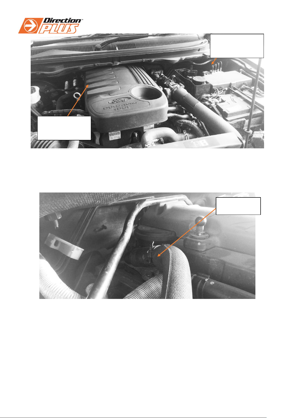
1. Begin by removing the engine cover to give access to the crankcase bypass hose in the front passenger corner.
Approximate mounting location
location
Direction-Plus™ PLPV621DPK_Install Page | 2
Ranger PX Engine Bay –Overall View
2. Begin by locating the factory bypass hose which runs from the valve cover on the driver’s side of the engine to the intake
pipe just after the concertina section. The hose is about 500mm in length and has a few bends in it. Once located, this
hose needs to be disconnected from the valve cover and the 90° fitting on the valve cover needs to be rotated to face
the rear of the vehicle.
Factory bypass hose location
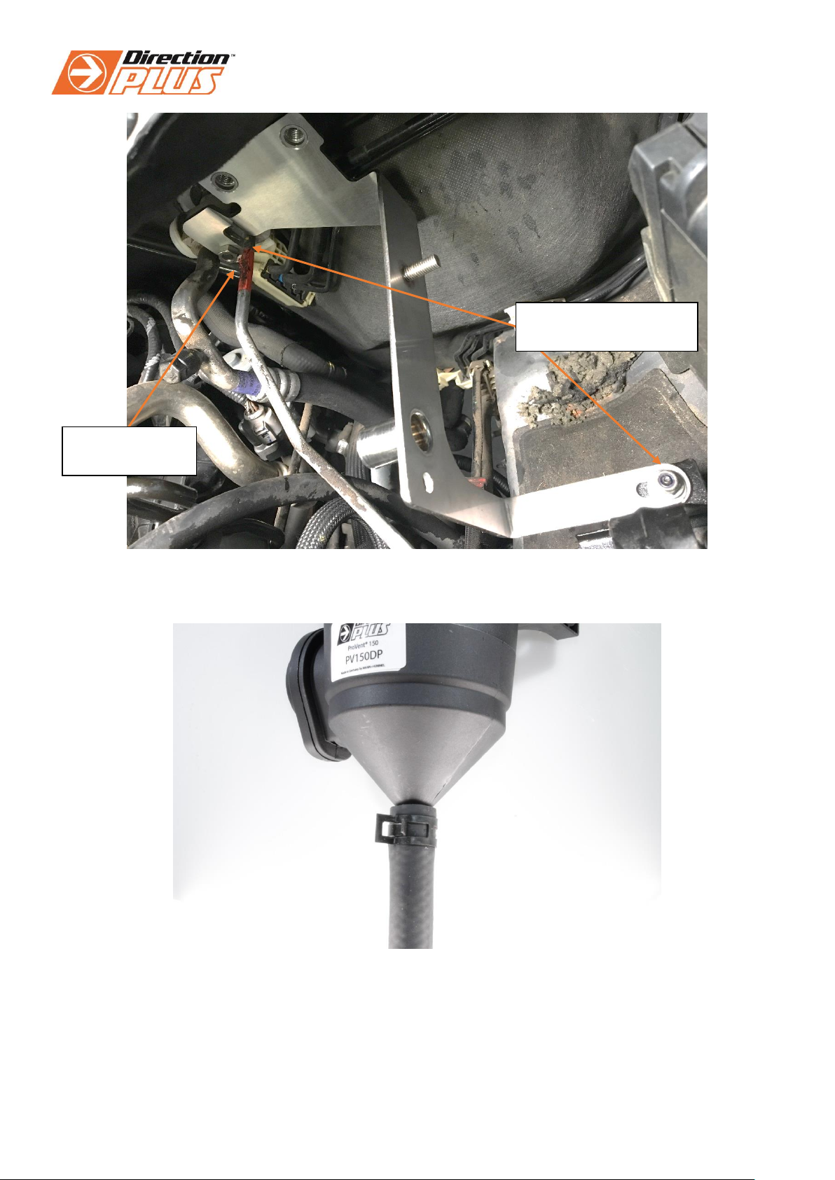
3. Locate the M6 nut located behind the fuse box on the passenger’s side. It needs to be removed to allow fitment of the
bracket.
ProVent® and Pre-
Filter kit mounts in
this corner
Bypass hose is
under the engine
cover in this corner
Disconnect hose
from here
Direction-Plus™ PLPV621DPK_Install Page | 3
Top down view: image shows new ProVent® bracket location
4. Connect the 12mm (1/2”) Hose to the underside of the catch can body, using a 12-20mm Clamp to secure it in place.
Provent® 150 with 12mm hose connected and secured with 12mm spring clamp
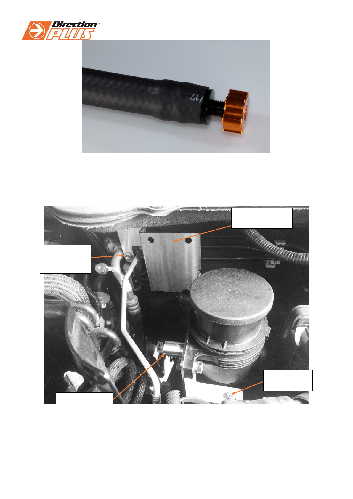
5. Feed the 12mm Hose down the side of the engine bay, under the vehicle to an out of the way location, making sure it is
clear of any suspension, driveline and exhaust components, fit the Tap hose tail into the hose and secure with a 12-
20mm clamp.
Mounting hole locations
for new ProVent Bracket
DO NOT REMOVE
FACTORY NUT
Direction-Plus™ PLPV621DPK_Install Page | 4
Hose tail and tap assembly inserted into 12mm hose, hose clamp not required
6. Fit the new bracket / ProVent® 150 bracket assembly onto the two mounting locations. Using the original M6 nut to
secure the end behind the fuse box. Once this is tight, use the supplied M8 nut to secure the other end of the bracket to
the stud between the air conditioning lines. We recommend the use of Loctite thread locker here.
Top down view: Ranger PX Engine Bay- Passenger’s Side
Supplied M8
Nut securing
bracket to stud.
Original M6
Nut reused
PL150DP Pre-filter
mounting location
Hose from engine
Direction-Plus™ PLPV621DPK_Install Page | 5
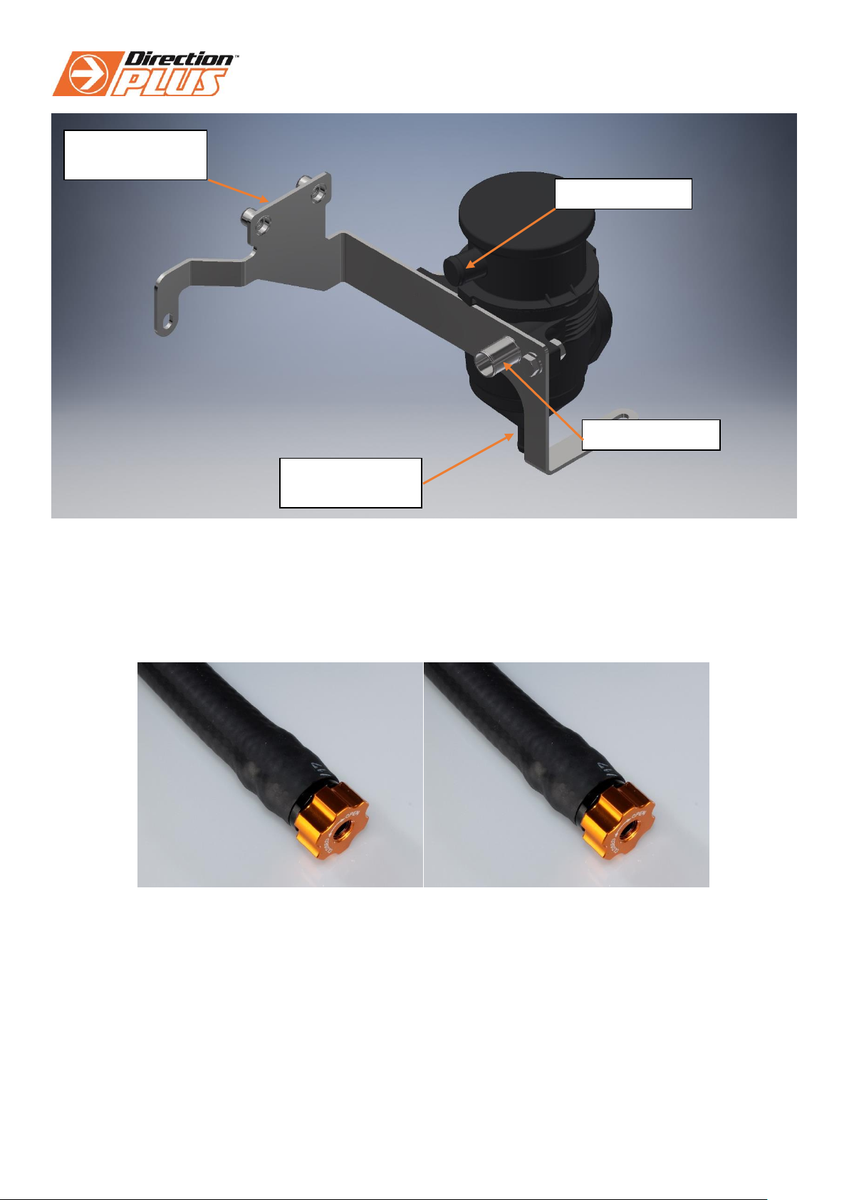
Pre-assembled Provent 150 with bracket.
7. Use the supplied cable ties to secure the 12mm hose into the location required under the vehicle to prevent movement.
Note: Leave a slight amount of slack in the line where the body and chassis join to prevent stretching the hose.
8. Make sure the tap position is closed and avoid placing the tap in a location in which it will fill with dirt and mud.
Left image –Tap Open. Right image –Tap Closed.
Hose from engine
Hose to air intake
Connect 12mm
drain Hose Here
PL150DP Pre-filter
mounting location
This manual suits for next models
1
Other Direction Plus Automobile Accessories manuals

Popular Automobile Accessories manuals by other brands


ULTIMATE SPEED
ULTIMATE SPEED 279746 Assembly and Safety Advice

SSV Works
SSV Works DF-F65 manual

ULTIMATE SPEED
ULTIMATE SPEED CARBON Assembly and Safety Advice

Witter
Witter F174 Fitting instructions

WeatherTech
WeatherTech No-Drill installation instructions

TAUBENREUTHER
TAUBENREUTHER 1-336050 Installation instruction