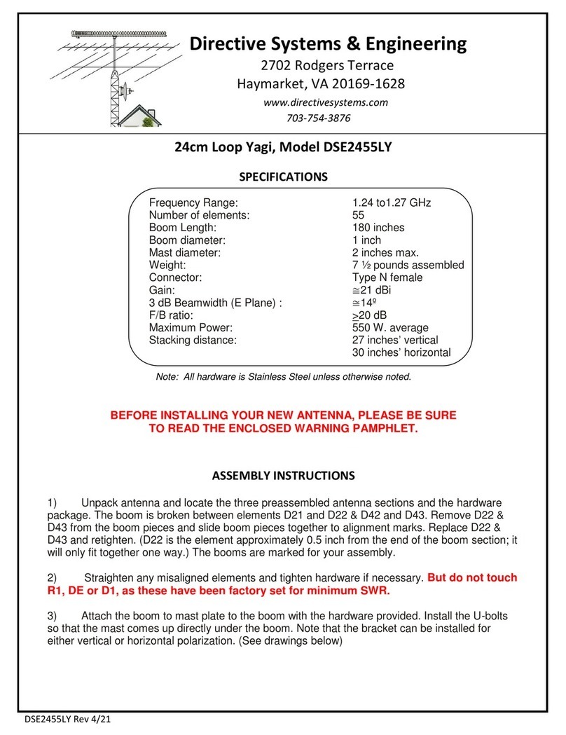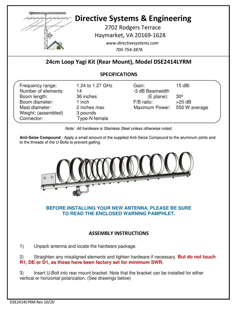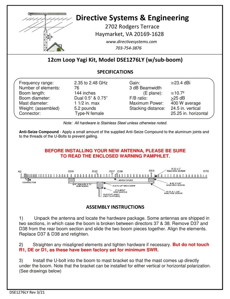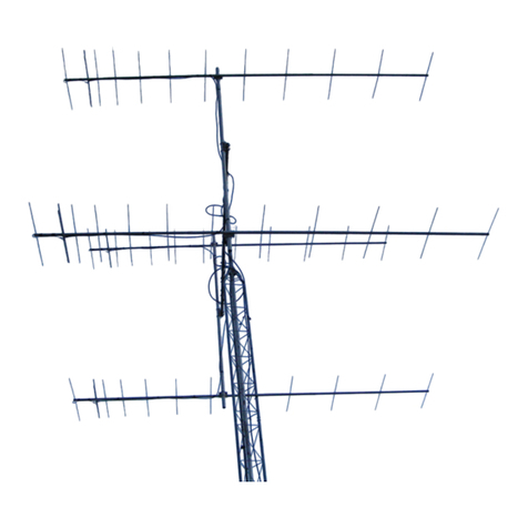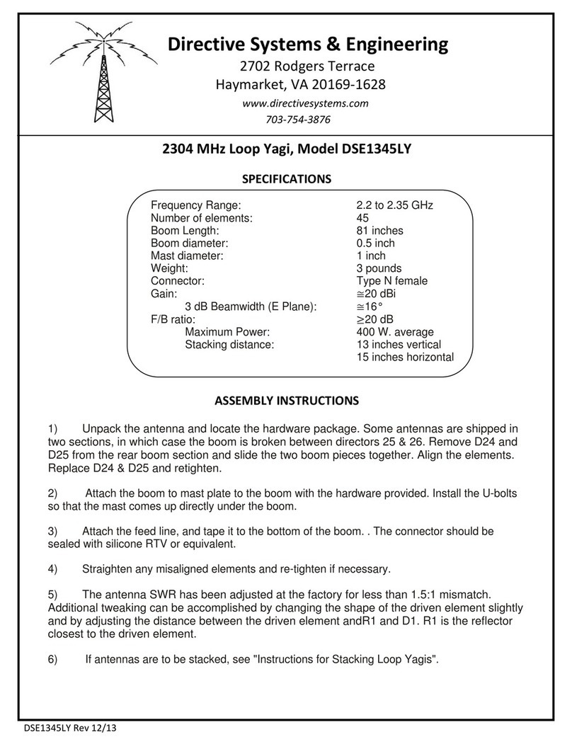
ASSEMBLY INSTRUCTIONS DS 88-8ASSEMBLY INSTRUCTIONS DS 88-8
1. Observe the parts list and diagrams ( fig 1 thru 4.) below, and verify that all parts required for assembly are included. The
hardware is packaged in a separate plastic bag. all elements and mounting blocks are supplied ready for assembly.
2. observe Figure 1 & 2, and identify each element. Elements are marked with black marker for proper position on the
boom. Assemble the boom as shown in FIG #1. Insert tubing to the alignment marks provided. Use 2" machine screws and
worm clamps to attach boom sections. Start assembling the elements in accordance with figure 1, and fasten the #1, and 4
thru 8 elements to the boom as shown. Use 1/4-20 U bolts and 1/4" hardware with element bracket. Start from the rear,
locate el #1 1" from the end of the boom. The two holes drilled in the boom are for elements 2 & 3. These holes should be
nearest the longest element. The remaining element locations
3. Assemble the two driven elements as shown in figure 3 and place them on the boom as well. These two elements are
connected together with the two 3/8" wide x 10 3/4" long PHASING STRAPS as shown in figure 4. Note that your lead in
wire will connect to element #3. ( toward the front )
4. Attach the boom to mast plate at the balance point of the antenna. (See FIG 2.) Attach a 75 ohm coaxial lead in cable to
the #8-32 machine screw terminals on element #3 (See Fig. 4). Prepare the cable as shown, and tape the cable to the
supporting mast to avoid movement in windy weather. Place the antenna on your support mast and tighten U-bolts to lock
antenna in position. The antenna elements should be parallel to the horizon for proper horizontal polarization. Maximum
pickup will be as shown in Fig #1, in the direction away from the coax cable attachment point.
DESCRIPTION
Boom, 1 3/8" x 72" ( Rear section drilled 3X)
Boom, 1 1/2" x 72" ( Mid section )
Element block ( aluminum)
Insulator block
Phasing strap, 3/8" x 10 3/4" long
Aluminum half washer
8-32 x 2" machine screw
8-32 X 1 1/2" machine screw
8-32 hex nut
#8 lock washer
#8 Solder lug
1/4-20 x 1 1/2" U-bolt
1/4" lock washer
1/4-20 Hex nut
5/16 X 2" U bolt
5/16 Hex nut
5/16 Lock washer
Boom to mast bracket 3" X 5"
Element #1 (Reflector) 1/2" OD X 66"
Element #2 (Dipole 1) 1/2" OD X 28 15/16"
Element #3 (Dipole 2) 1/2" OD X 29 1/8"
Element #4 (Director 1) 1/2" OD X 60 1/4"
Element #5 (Director 2) 1/2" OD X 58 13/16"
Element #6 (Director 3) 1/2" OD X 57 7/16"
Element #7 (Director 4) 1/2" OD X 56 9/16"
QUANTITY
2
1
6
2
2
4
4
4
8
8
2
8
16
16
2
4
4
1
1
2
2
1
1
1
1
QUANTITY
2
1
6
2
2
4
4
4
8
8
2
8
16
16
2
4
4
1
1
2
2
1
1
1
1
PARTS LISTPARTS LIST
At this time, check all elements for tightness and position. Seal the
end of the coax cable with RTV. Locate the antenna away from metal
objects, otherwise some de-tuning and loss of performance will
result.
5. If you are using a rotator, be sure that you align the front of your
DS 88-8 to coincide with the indication on your rotator controller.
Maximum signal is shown in Figure 1. at right.
177 Dixon Road
Lebanon, ME. 04027
Tel 207-658-7758
177 Dixon Road
Lebanon, ME. 04027
Tel 207-658-7758
DS888-2
ELEMENT SPACING
element #1element #1
element #2element #2
element #4element #4
element #5element #5
element #6element #6
element #7element #7
element #8element #8
66"
28 15/16"
28 15/16"
60 1/4"60 1/4"
58 13/16"58 13/16"
57 7/16"57 7/16"
56 9/16"56 9/16"
55 13/16"55 13/16"
X2X 2
element #3element #3 29 1/8"29 1/8"
X2X 2
1"
7 9/16
7 9/16
17 5/16"17 5/16"
33 3/4"33 3/4"
67 1/8"67 1/8"
112 3/4"112 3/4"
162 15/16"162 15/16"
207"
MAX
SIGNAL
MAX
SIGNAL
ELEMENT LENGTHS
FIGURE 1.FIGURE 1.
