dirna Bergstrom bycool COMPACT 3.0 User manual
®
1001238893
F-4218 rev.01
Instrucciones de Montaje ES
Mounting Instructions EN
Instructions de Montage FR
Montageanweisungen GE
Istruzioni di Montaggio IT
Montážní návod CZ
Руководство по эксплуатации RU
COMPACT 3.0
Dirna Bergstrom SCANIA
1001238153 2533319
PGR
2
COMPACT 3.0
ES
®
!
Atención
Al instalar el equipo de aire acondicionado en el techo
se debe proteger la parte superior de la cabina con un
paño ó manta protectora para evitar posibles arañazos.
Al instalar Compact en el techo hay que tener en cuenta
que, normalmente, las cabinas que vienen provistas de
escotilla, tienen una estructura suciente para soportar
el peso del equipo. Sin embargo, cuando no ocurra así y
sea necesario realizar corte en el techo ó incluso si en el
caso de llevar escotilla el material no es lo sucientemente
resistente (caso de techo de bra, plástico, etc...) es el
instalador el que debe decidir, bajo su responsabilidad,
sobre la necesidad de reforzar el techo para evitar
posibles deformaciones, roturas, entradas de agua, etc...
habilitando los medios para que esto no ocurra.
!
Atención
Si durante el montaje el equipo se inclina o se abate
la cabina con el equipo montado, se deberá esperar
un mínimo de 60 minutos, desde que el quipo quede
horizontal, antes de ponerlo en marcha.
!
Atención
En vehículos en los que la conexión eléctrica se
realice a baterías adicionales independientes de las de
arranque del vehículo, es opcional, la conguración
de la electrónica a nuevos parámetros de corte de
batería (ver página 9).
Herramientas
Juego de Llaves Torx
Juego de Llaves Allen
Llave ja 13
Tijeras
Documentación incluída
Instrucciones de montaje 1001238893
Manual del usuario 1001247858
Diagnosis de averías 1001238883
Listado de recambios 1001238888
!
Advertencias
!
El personal instalador debe poseer una formación
suciente en Aire Acondicionado de vehículos.
!
dirna Bergstrom, s. l. queda exenta de
responsabilidad si se producen averías que procedan
de una inadecuada manipulación o instalación
del equipo, o por modicaciones y sustituciones
efectuadas sin nuestra expresa autorización por
escrito.
!
Equipo precargado con gas refrigerante R-134a.
(No manipular el circuito de gas refrigerante).
!
Véase procedimiento de garantía del producto
incluido en Diagnosis de Averías.
!
Véase Manual de Usuario del equipo para el correcto
funcionamiento del mando a distancia y del panel de
control.
!
Al nalizar la instalación se debe entregar al usuario:
Manual del Usuario, Garantía y Diagnosis de
averías.
Recomendaciones
Para el montaje
• Antes de iniciar el montaje leer las instrucciones y
seguirlas durante el proceso de instalacion.
• Usar las herramientas adecuadas para cada operación.
Electricidad
• Desconectar la llave de contacto.
• Desconectar la batería antes de empezar el montaje.
• Asegurar el conexionado de los componentes
eléctricos, vericando su correcto encaje.
Simbología
Frágil
Atención corte!
Riesgo eléctrico
COMPACT 3.0
3
ES
®
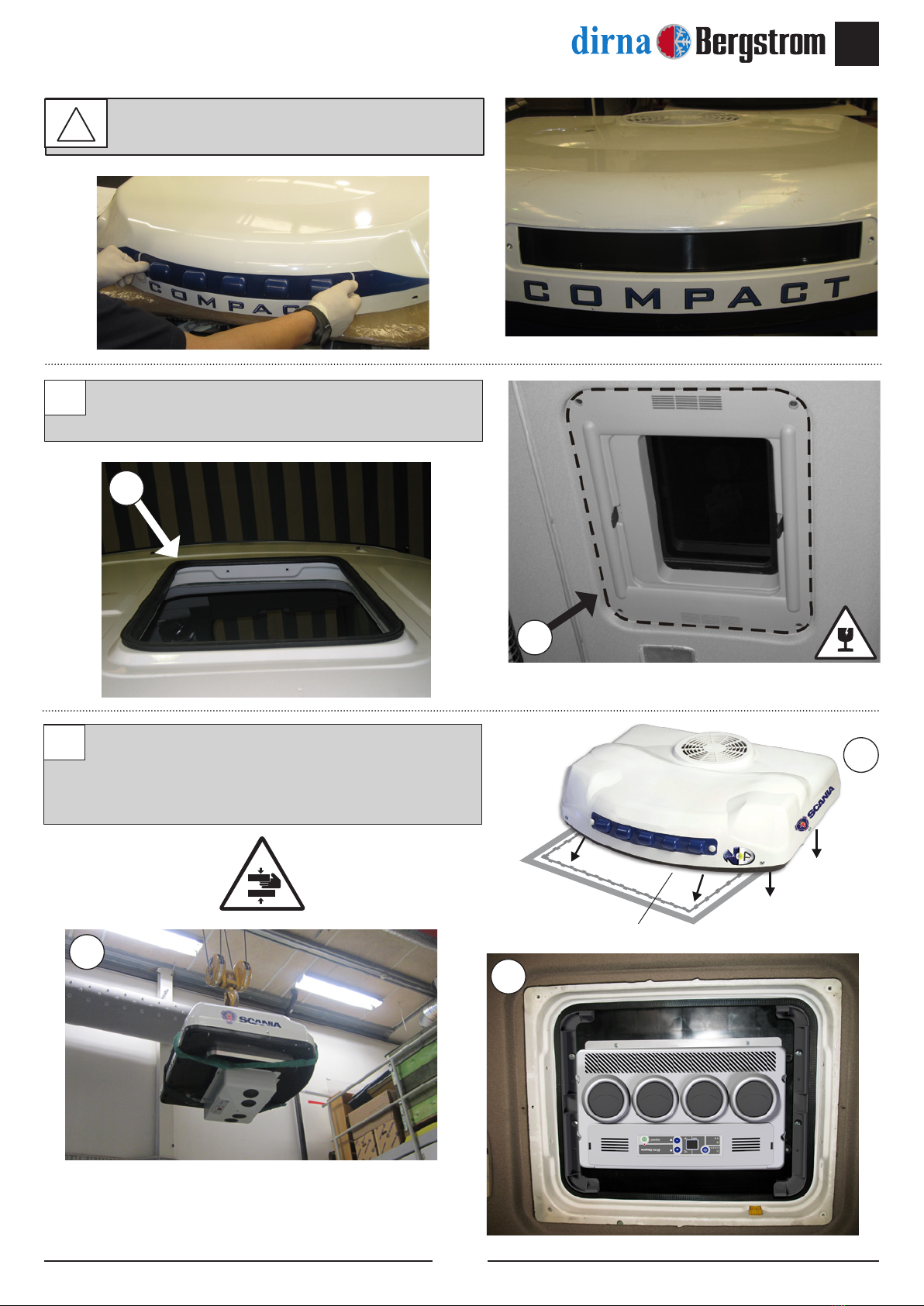
Escotilla
Desmontar tapa escotilla, los elementos de ja-
ción y entregar éstos al cliente.
EXTERIOR CABINA:
Posicionar el Compact en el hueco de la escotilla
sobre cubrecantos original.
1
2
1
2
2
2
1
!
Antes de empezar con el montaje, montar
rejilla entrada aire delantera.

4
COMPACT 3.0
ES
®
Colocar (2) soportes sujeción con (4) tornillos
M8/125x50 y (4) arandelas planas y (4) arandelas
grower. Apretar hasta hacer tope.
Desmontar tornillos originales de la tapa fusibles y
extraer hacia la parte superior el panel (B).
3
4
3
3
3
A
4
COMPACT 3.0
5
ES
®
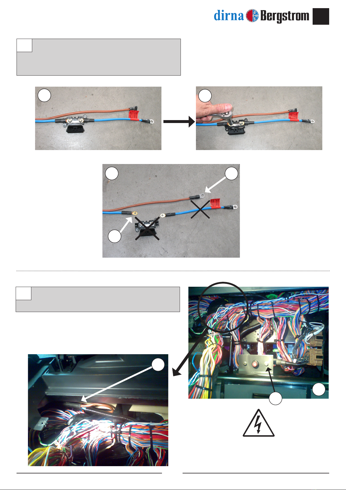
En vehículos equipados con fusible original.
Desconectar de los cables de alimentación el
fusible y su soporte y desechar éstos.
Conectar cable de alimentación suministrado color
azul (+) con fusible original en el punto A.
5
6
55
5
A
6
6
A
B
Fusible original
Other manuals for bycool COMPACT 3.0
5
Table of contents
Languages:
Other dirna Bergstrom Accessories manuals


