dirna Bergstrom CAMPER User manual

220AA60202
F-4218 rev.01
®
Instrucciones de Montaje ES Spanish
Mounting Instructions EN English
Instructions de Montage FR French
Montageanweisungen GE German
Istruzioni di Montaggio IT Italian
IInstruções de Montagem PT Portuguese
IATF 16949
Calidad en
Automoción
ISO 9001
Empresa
Registrada
CAMPER

2
ES CAMPER
®
!
Atención
El acondicionador evaporativo funciona tomando
aire del exterior que es introducido en la cabina.
Es esencial que este aire no se estanque en el
interior, lo que produciría un exceso de humedad.
Todas las cabinas de vehículos modernos van
dotados de rejillas de renovación de aire, por los
que sale el aire necesario, por ejemplo, para la
calefacción.
El instalador deberá cerciorarse de la existencia
de estas rejillas y, en caso de no existir, deberá
instalarlas.
Por su parte, el usuario deberá vigilar
periódicamente que éstas rejillas no están
obturadas por suciedad.
Herramientas
Carraca con llave de paso de 10
Destornillador de estrella TOP 10
Llave ja de 10
Llave allen de 6
Documentación incluída
Instrucciones de montaje 220.AA6.0202
Manual del usuario 220.AA6.0200
Diagnosis de averías 220.AA6.0201
Piezas suministradas 220.RE0.00105
!
Advertencias
!
dirna Bergstrom, s.l. queda exenta de
responsabilidad si se producen averías que
procedan de una inadecuada manipulación ó
instalación del equipo, ó por modicaciones y
sustituciones efectuadas sin nuestra expresa
autorización por escrito.
!
Importante
Deberán ser entregados al usuario: Tapa de
invierno y el Manual del usuario.
Se recomienda al instalador leer el mencionado
manual, antes de entregarlo, para informarse
del mantenimiento y recomendaciones sobre el
evaporativo instalado.
Recomendaciones
Para el montaje
• Antes de iniciar el montaje leer las instrucciones y
seguirlas durante el proceso de instalacion.
• Usar las herramientas adecuadas para cada
operación.
Electricidad
• Desconectar la llave de contacto.
• Desconectar la batería antes de empezar el montaje.
• Asegurarelconexionadodeloscomponentes eléctricos,
vericando su correcto encaje.
Par de apriete (N.m)
Rosca Calidad Acero Llave
8.8 10.9
M4/60 2.9 4.2 7
M5/80 5.5 7.5 8
M6/100 10 13 10
Las indicaciones relativas a posición son:
DERECHA: Lado pasajero
IZQUIERDA: Lado conductor

3
ES
CAMPER
®
ventilador
ltro húmedo
marcados con cinta
tubo retorno
depósito bycool
otador
batería adicional
sensor nivel
bomba de agua
depósito del vehículo
interruptor original
grifos eléctricos
“T” suministrada
Tubo original
Control electrónico
- 8 velocidades de aire
- 3 velocidades bomba de agua
- función despertador
- mando a distancia
VISTA GENERAL

4
ES CAMPER
®
EN CASO DE LLEVAR ESCOTILLA ORIG. SE
PUEDE UTILIZAR DICHO HUECO (QUITANDO
ESCOTILLA) PARA EL MONTAJE DEL
EVAPORATIVO, EN OTRO CASO:
*Posicionar evaporativo sobre el techo, evitando
roces con placas solares, antenas, etc. tomando
esa referencia, seguir los siguientes pasos:
Presentar marco centrado sobre el techo (desde
el interior del habitáculo) y marcar por el interior
del contorno.
Dar (4) taladros en las esquinas de la marca
desde el interior y unir esos taladros por la parte
superior. Cortar guata y falso techo (con cuchillo
o cúter ) y posteriormente realizar el corte, por
la parte exterior, con sierra de calar, teniendo
como guía, la marca realizada anteriormente.
!
CUIDADO AL REALIZAR EL CORTE, POR
LA POSIBILIDAD DE ENCONTRARSE
CON PASO DE CABLES.
A
1
2
1
1
2
2

5
ES
CAMPER
®
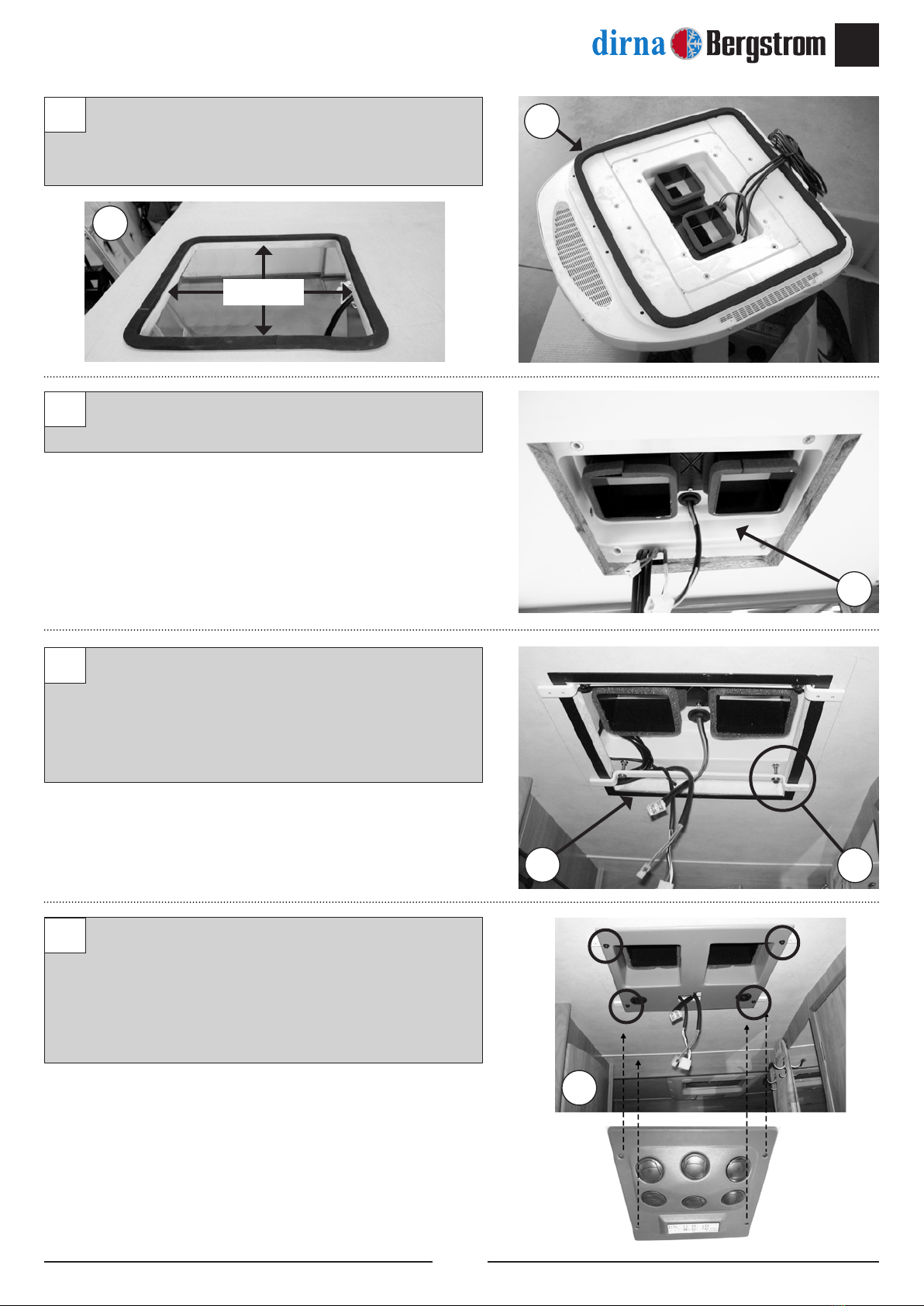
Colocar junta de montaje alrededor del corte y en
la parte inferior del evaporativo, como se indica
en la foto. Sellar con silicona interiormente.
Montar evaporativo desde el exterior y desde el
interior, centrarlo en el corte del techo.
Montar marco, jando con (4) tornillos rosca
chapa y sobre el marco y a taladros del
evaporativo, montar los (2)soportes sujeción
con (4) espárragos M6/100x60, con tuercas y
arandelas planas.
Fijar canalizador a los (2)soportes con (4)tornillos
M4/70x10 y pasar cableados.
Conectar cables al frente y jar frente con
ventanillas sobre el canalizador montado
anteriormente, con (4) M4/70x15.
3
4
5
6
3
4
5
6
3
Silicona
5

6
ES CAMPER
®
Para pasar tubos y cables (desde techo a
depósito agua), utilizar bajantes originales. Si
no se puede:
a- Presentar bajante suministrada, por la parte
mas idónea y dar taladro en el centro, hacia
arriba.
b- A continuación y desde el techo, con la
referencia de ese taladro, dar corte según
medidas.
Fijar la bajante con tornillo rosca chapa
Ø3.5x13mm. e ir recortando, por donde sea
necesario según su recorrido.
7
8
7
7
19/21
35/38
8
8
INTERIOR CABINA
EXTERIOR TECHO

7
ES
CAMPER
®
Desde el techo meter los (3) tubos y (2) cables,
hacia abajo.
a- Presentar las (2) canaletas blancas, a 90º y
cortar en el punto de encuentro con taladro.
b- Una vez pasados tubos y cables por las
canaletas sellar con silicona en la zona del
taladro, para dejar ja la posición de esos
tubos y cables.
c- Colocar junta de montaje.
d- Fijar canaletas con tornillo rosca chapa
Ø3.5x13mm. y volver a sellar todo alrededor,
para evitar entradas de agua.
910
a
b
c
10
d
d
Presentar el depósito en el sitio mas idóneo
(interior, maletero, etc), con el soporte inferior (en
caso de no poder apoyar en el suelo) y marcar los
puntos de jación (del soporte inferior y los dos
superiores), donde posteriormente realizaremos
los taladros, a diámetros y cotas indicadas.
11 28
==
28
320
160
165
188
(2) Ø 3
(4) Ø 3
11
Para taladros superior
si no lleva soporte inferior

8
ES CAMPER
®
Fijar soporte inferior (en caso de llevar) con (2)
tornillos rosca chapa.
Montar los (2) soportes superiores de las cintas,
con (4) tornillos rosca chapa. Colocar las cintas
como se muestra.
Fijar depósito sobre el soporte ( o suelo) con las
cintas.
a- Conectar tubos, cajas y grifo agua.
12
13
14
13
12
14
14
a
Tubo retorno Grifo agua
Entrada agua
Salida a bomba
*

9
ES
CAMPER
®
CONEXIÓN TUBO DESAGÜE EN
DEPÓSITO
Colocar tubo negro Ø9 x Ø13, en racor de
seguridad indicado, para evitar (en caso de fallo
del otador) que el agua vierta en el interior del
vehículo.
Sacar el otro extremo del tubo hacia el exterior
del vehículo.
Colocar válvula de drenaje suministrada.
1
2
3
1
3

10
ES CAMPER
®
b- Cortar tubo original del depósito de agua fria,
e intercalar “T” (Ø8 ó Ø10 según el tubo),para
poder conectar con tubo negro suministrado.
Fijar con (3)abrazaderas Ø12
c- Los (2) tubos marcados con cinta, van a la
“Y” del retorno del depósito
Aprovechar cualquier taladro original del chasis
para sujetar bomba de agua, en parte inferior
del vehículo, con silentblock, arandela y tuerca.
a- Para paso de tubos y cableado, hacia la
bomba, dar taladro (hacia el exterior), según
medidas y sellar posteriormente con silicona.
El tubo de entrada a la bomba debe colocarse
con ángulo de caída, jando ambos tubos
(entrada y salida), con (2) abrazaderas Ø10.
14
15
16
Original
14
T
15
19
35
15
16
15

11
ES
CAMPER
®
En caso de llevar grifos eléctricos, conectar
cableado, desde el sensor del otador del
depósito, al interruptor original de grifos, situado
en el depósito de agua original.
a- cable azul
b- cable marrón.
17 17
a
b

12
ES CAMPER
®
BOMBA AGUA
¡AVISO IMPORTANTE!
Conectar cable R a fusible.
Si se invierte la polaridad, el control
electrónico queda dañado irreversi-
blemente.
FLOTADOR
12
RELÉ
BOMBA
CONTACTO
BOMBA
MOTOR
FUSIBLE
BATERÍA
BOMBA AGUA
FLOTADOR
HORIZONTAL

13
ES
CAMPER
®

14
CAMPER
®
EN
!
Important
Evaporative air conditioner works by taking air
from outside and introducing it in cabin. It is
essential that air does not stagnate inside, which
would produce an excess of humidity. All modern
cabins of vehicles are equipped with air inlets,
through which required air comes out as, for
instance, in the case of heating.
Assembler will have to check that these air inlets
do exist and, in case they do not, he will have to
mount them.
As for the user, he will have to periodically
make sure that these air inlets are not blocked
by dirt.
Tools
Ratchet with 10mm shut-off valve
TOP 10 star screw-driver
10 mm spanner
6 mm allen wrench
Documentation included
Mounting instructions 220.AA6.0202
User’s guide 220.AA6.0200
Troubleshooting 220.AA6.0201
Included parts 220.RE0.00105
!
Warnings
!
Dirna Bergstrom, s.l. will not be held
responsible for any faults arising from
inappropriate handling or installation of
the equipment, or due to modications or
replacements carried out without our written
authorisation.
!
Important
The following parts will have to be delivered to
user: Winter cover and user’s handbook.
The assembler is recommended to read the above
mentioned handbook, before giving it to user, in
order to inform himself of the maintenance and
recommendations on the evaporative equipment
being assembled.
Mounting
Guidelines
• Prior to assembly, read the instructions and follow these
throughout the mounting operations.
• Use the appropiate tools for each operation.
Electricity
• Switch the connector off.
• Disconnect the battery before starting mounting
operations.
• Verify that the electrical components have been
connected correctly.
Driving torques (N.m)
Fillet Steel Quality Wrench
opening
8.8 10.9
M4/60 2.9 4.2 7
M5/80 5.5 7.5 8
M6/100 10 13 10
References to position:
RIGHT: Driver’s right hand
LEFT: Driver’s left hand

15
CAMPER
®
EN
fan
wet lter
marked with tape
return hose
bycool tank
oat
addtional battery
level sensor
water pump
vehicle tank
original switch of
electric valves
Provided “T”
original hose
Electronic control
- 8 air speeds
- 3 water pump speeds
- alarm clock function
- remote control
GENERAL VIEW

16
CAMPER
®
EN
IF VEHICLE IS EQUIPPED WITH ORIGINAL
HATCH, THE SPACE CAN BE USED
(REMOVING HATCH) TO ASSEMBLE
EVAPORATION SYSTEM, IF NOT:
*Position evaporation system on roof, avoiding
friction with solar panels, aerials, etc. and taking
this reference, follow steps described below:
Present frame so that it is centred on roof (from
inside of passenger cell) and mark from inside
of outline.
Drill (4) holes on corners of mark from inside of
vehicle and join these holes from outside. Cut
padding and false roof (using knife or cutter)
and then cut from outside with jigsaw and using
previously made mark as guide.
!
BE CAREFUL WHILE CUTTING,
POSSIBILITY OF FINDING CABLES
PASSAGE.
A
1
2
1
1
2
2

17
CAMPER
®
EN
Place assembly joint around cut and in lower part
of evaporation system, as indicated on picture.
Seal inside with silicone.
Assemble evaporation system from outside and
from inside, centre it on cut made in roof.
Assemble frame, fastening it with (4) sheet
thread screws. Assemble (2) fastening supports
on previously mentioned frame and holes of
evaporation system using (4) M6/100x60 bolts,
with nuts and at washers.
Fasten canalisation system to both supports
using (4) M4/70x10 screws and put cables
through.
Connect cables to front and fasten front with
windows on canalisation system previously
assembled, using (4) M4/70x15 screws.
3
4
5
6
3
4
5
6
3
Silicone
5

18
CAMPER
®
EN
To lead hoses and cables (from roof to water
tank), use original downpipes.
If it is not possible:
a- Presentprovided downpipeto mostconvenient
part and drill hole in centre, upwards.
b- Cutaccordingtomeasures,fromroofandusing
previously mentioned hole as reference.
Fasten downpipe with Ø3.5x13 sheet thread
screw and cut where necessary, depending on
required length.
7
8
7
7
19/21
35/38
8
8
CABIN INSIDE
ROOF OUTSIDE

19
CAMPER
®
EN
From roof, lead the (3) hoses and (2) cables
downwards.
a- Present both white grooves at 90º and cut
where they meet hole.
b- Once hoses and cables have been led along
grooves, seal hole area using silicone so as
to leave hoses and cables in a xed position.
c- Place assembly joint.
d- Fasten grooves with Ø3.5x13 sheet thread
screws and seal all around to avoid water
from entering.
910
a
b
c
10
d
d
Present tank on most convenient place (inside,
in boot, etc), with lower support (in case it
can not rest on oor). Mark fastening points
(of lower support and both upper ones) and
drill holes respecting indicated diameters and
measures.
11 28
==
28
320
160
165
188
(2) Ø 3
(4) Ø 3
11
For upper holes if no
lower support is used

20
CAMPER
®
EN
Fasten lower support (in case it is used) with (2)
sheet thread screws.
Assemble both upper supports for straps,
using (4) sheet thread screws. Place straps as
shown.
Fasten tank on support (or oor) with straps.
a- Connect hoses, boxes and water faucet.
12
13
14
13
12
14
14
a
Return hose Water faucet
Water inlet
Outlet to pump
*
This manual suits for next models
1
Table of contents
Languages:
Other dirna Bergstrom Accessories manuals
Popular Accessories manuals by other brands

Optex
Optex HX-80N installation instructions

Campbell
Campbell 61302V instruction manual

Qel
Qel QIRF Installation, operation and maintenance manual

GAI-Tronics
GAI-Tronics XAAB002A Installation and service manual

Pepperl+Fuchs
Pepperl+Fuchs RMS-G-RC Brief instructions

Echo
Echo KICK GUARD X7503202102 Installation and use