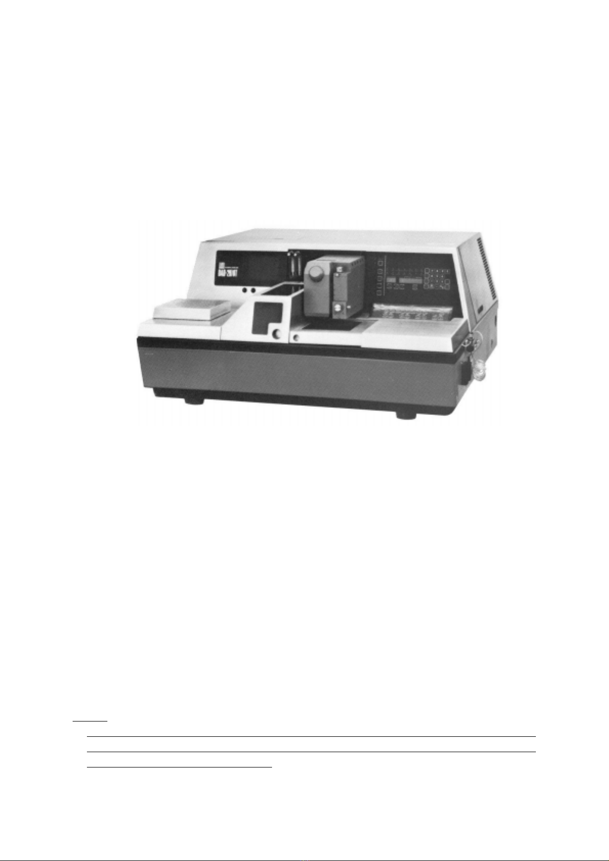
DISCO DAD 2H/6T User manual

AUTOMATIC DICING SAW
DAD-2H/6T
DAD-2H/6TM
TROUBLESHOOTING GUIDE
First Edition-October, 1984.
Revised-September, 1991. [8] This manual is solely for the use of employees of Disco Corporation,
its authorized representatives and users of the actual equipment. This
manual may not be reproduced in any from, or shown to third parties
without written permission from Disco Corporation.
US
I
NG
LI
N
T-FREE PAPER

i
CONTENTS
INTRODUCTION page
A. GENERAL
Symbol letter ..............................................................................................................................................A-1
B. CONSTRUCTION
1. Composition and Arrangement of Mechanical Equipment.....................................................................B-1
2. Composition and Arrangement of Electrical Equipment........................................................................B-2
3. Pneumatic, Water Schematic Diagram...................................................................................................B-3
C. CIRCUIT DIAGRAM
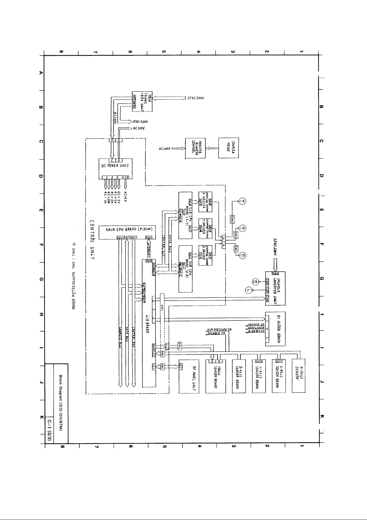
Block Diagram............................................................................................................................................C-1
Machine Wiring Diagram (1/6) ..................................................................................................................C-2
Machine Wiring Diagram (2/6) (2H/6T 90°)..............................................................................................C-3
Machine Wiring Diagram (3/6) (2H/6T 360°)............................................................................................C-4
Machine Wiring Diagram (4/6) (2H/6TM).................................................................................................C-5
Machine Wiring Diagram (5/6) ..................................................................................................................C-6
Machine Wiring Diagram (6/6) ..................................................................................................................C-7
Control Unit Wiring Diagram.....................................................................................................................C-8
Control Unit Wiring Diagram.....................................................................................................................C-9
Control Unit Wiring Diagram...................................................................................................................C-10
DC Power Unit .........................................................................................................................................C-11
CPU..........................................................................................................................................................C-12
Input/Output .............................................................................................................................................C-13
(Not Assigned)..........................................................................................................................................C-14
Driver Control-1, 2 (X, Y, Z, θ)...............................................................................................................C-15
Driver(X,Y,Z,θ)....................................................................................................................................C-16
Spindle Inverter ........................................................................................................................................C-17
(Not Assigned)..........................................................................................................................................C-18
(Not Assigned)..........................................................................................................................................C-19
(Not Assigned)..........................................................................................................................................C-20
(Not Assigned)..........................................................................................................................................C-21
(Not Assigned)..........................................................................................................................................C-22
(Not Assigned)..........................................................................................................................................C-23
(Not Assigned)..........................................................................................................................................C-24
891110

ii
(Not Assigned)..........................................................................................................................................C-25
(Not Assigned)..........................................................................................................................................C-26
(Not Assigned)..........................................................................................................................................C-27
(Not Assigned)..........................................................................................................................................C-28
(Not Assigned)..........................................................................................................................................C-29
(Not Assigned)..........................................................................................................................................C-30
X-axis Sensor P.C. Board.........................................................................................................................C-31
Y-axis Sensor P.C. Board.........................................................................................................................C-32
Z-axis Sensor P.C. Board .........................................................................................................................C-33
Touch Sensor P.C. Board .........................................................................................................................C-34
FP5 DC5 Circuit Diagram........................................................................................................................C-35
Trans-Box for Domestic...........................................................................................................................C-36
Trans-Box for Export................................................................................................................................C-37
Control Box A (2H/6T) ............................................................................................................................C-38
(Not Assigned)..........................................................................................................................................C-39
Control Box A (2H/6TM).........................................................................................................................C-40
Control Box B...........................................................................................................................................C-41
Control Box C...........................................................................................................................................C-42
Operation Panel ........................................................................................................................................C-43
(Not Assigned)..........................................................................................................................................C-44
Operation Panel (2H/6T) ..........................................................................................................................C-45
Operation Panel (2H/6TM).......................................................................................................................C-46
DC Power P.C. Board...............................................................................................................................C-47
Main CPU Board......................................................................................................................................C-48
Input/Output P.C. Board...........................................................................................................................C-49
(Not Assigned)..........................................................................................................................................C-50
SubCPUBoard(X,Y,Z,θ).....................................................................................................................C-51
Driver P.C. Board.....................................................................................................................................C-52
D. MAINTENANCE
1. Maintenance and Inspection ...................................................................................................................D-1
E. CHECKING PROCEDURES FOR TROUBLESHOOTING
1. Power....................................................................................................................................................E-1
2. Data Setting Operation .........................................................................................................................E-5
3. Manual Operation.................................................................................................................................E-7
891110

iii
4. Setting-up Operation...........................................................................................................................E-11
5. Semi/Fully Auto Operation.................................................................................................................E-15
6. Driver Control Circuit Board..............................................................................................................E-17
7. Driver..................................................................................................................................................E-19
8. Inverter ...............................................................................................................................................E-21
9. Self-diagnostics ..................................................................................................................................E-30
10. Inverter Alarm Resetting ....................................................................................................................E-35
F. ILLUSTRATIONS AND PARTS LIST
Exploded View of Main Body (A) .............................................................................................................F-1
Exploded View of Main Body (B)..............................................................................................................F-2
Exploded View of X-axis (90° Theta)..................................................................................................... F-3A
Exploded View of X-axis (Manual Theta) (MODEL DAD-2H/6TM).....................................................F-3B
Exploded View of X-axis (360° Theta)....................................................................................................F-3C
Exploded View of Y-axis ........................................................................................................................... F-4
Exploded View of Z-axis............................................................................................................................F-5
Exploded View of Piping (A)..................................................................................................................... F-6
Exploded View of Piping (B)..................................................................................................................... F-7
(Not Assigned)............................................................................................................................................F-8
(Not Assigned)............................................................................................................................................F-9
G. REGULAR INSPECTIONS
1. Daily Inspection, Maintenance and Adjustment.....................................................................................G-1
2. Weekly Inspection, Maintenance and Adjustment .................................................................................G-1
3. Monthly Inspection, Maintenance and Adjustment................................................................................G-2
4. Spindle Inspection ..................................................................................................................................G-2
5. I/O Circuit Board Jumper Setup Procedure............................................................................................G-3
H. CAMERA HEAD MONITOR TV
1. General ...................................................................................................................................................H-1
2. Features...................................................................................................................................................H-1
3. Composition of Equipment.....................................................................................................................H-2
4. Specifications..........................................................................................................................................H-2
5. Connections............................................................................................................................................H-4
6. Operating Procedures .............................................................................................................................H-4
J. MICROSCOPE MODEL DS
1. Specifications...........................................................................................................................................J-1
2. Adjustment and Repair............................................................................................................................J-1
910810910810

INTRODUCTION
891110
PREFACE
This manual describes the procedures to be performed in case of trouble with the DISCO DICING SAW
DAD-2H/6T and DAD-2H/6TM. A lot of information is given herin, which will help you to make the
machine operate at its best performance.
Caution:
This manual uses lint free paper. Since this paper is weakened by heat, do not place near heat. Also when
rubbing strongly with something such as an eraser, since the printing will be come thin and contaminated,
please take adequate precautions in handling.

A. GENERAL
A-1
840920
Table for Symbol Letter
Symbol letter - - - Component
C --- Capacitor
CN
J--- Connector
D --- Diode or Light Emitting Diode
F---Fuse
FLS --- Bidirectional Thyristor
FAN --- Fan
KD --- Printed Circuit Board
L --- Choke Transformer
LED --- Light Emitting Diode
Q --- Transistor
R --- Resistor
RF --- Rectifier
RY --- Relay
S---Triac
TR --- Transformer
VR --- Potentiometer

B.CONSTRUCTION

B-1
B. EQUIPMENT COMPOSITION AND SCHEMATIC DIAGRAM
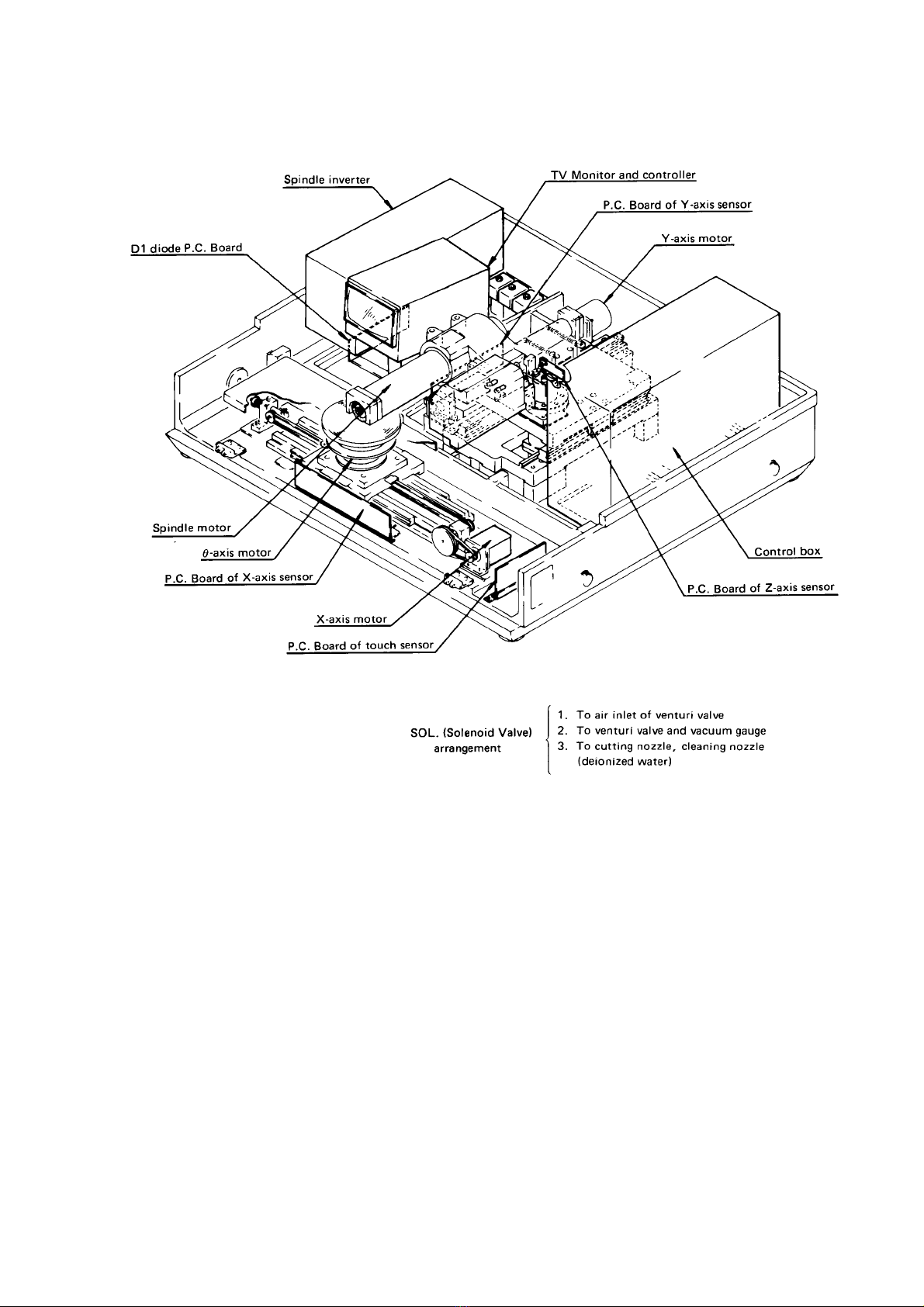
1. Composition and Arrangement of Mechanical Equipment
Fig. B-1
910110
B-2
2. Composition and Arrangement of Electrical Equipment
Fig. B-2
910810
910810

B-3
891110
3. Pneumatic, Water Schematic Diagram
Fig. B-3
891110

C.CIRCUIT DIAGRAM

C-i
891110
CONTENTS
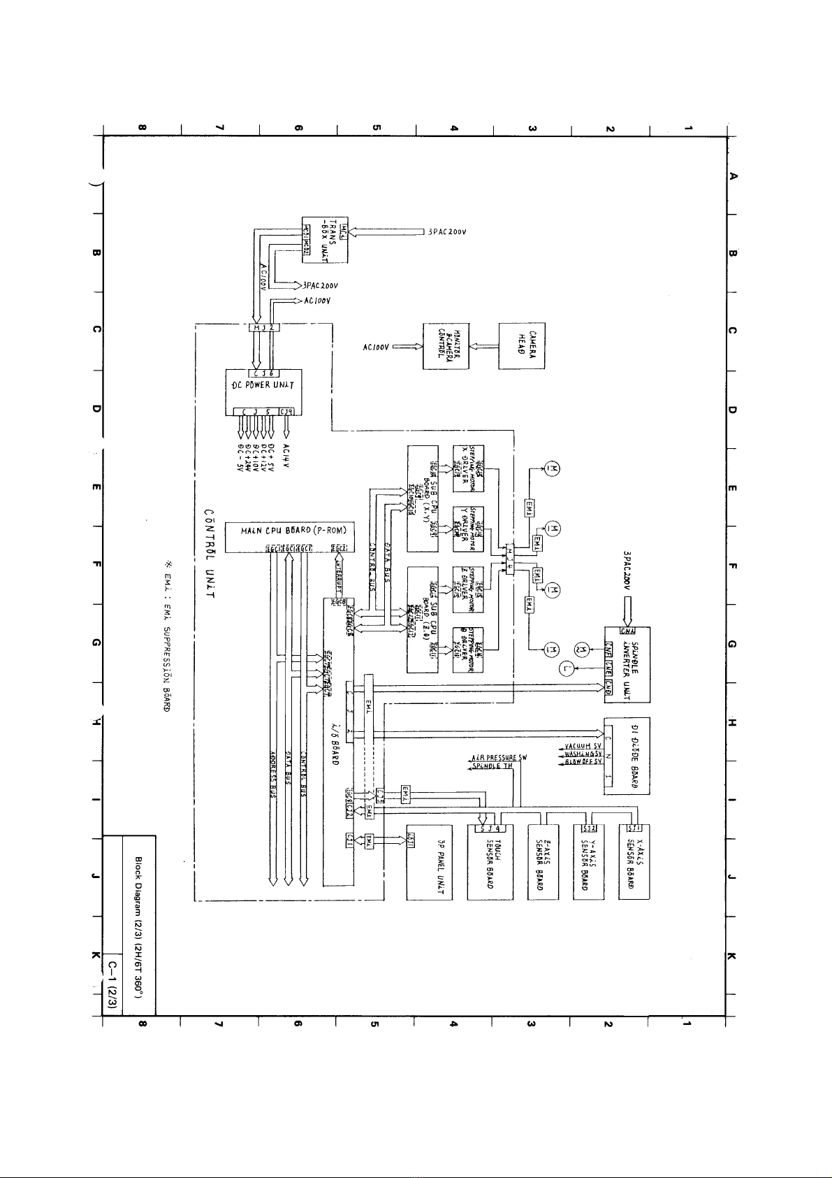
Block Diagram......................................................................................................................................C-1
Machine Wiring Diagram (1/6) ............................................................................................................C-2
Machine Wiring Diagram (2/6)(2H/6T 90°) ........................................................................................C-3
Machine Wiring Diagram (3/6)(2H/6T 360°)......................................................................................C-4
Machine Wiring Diagram (4/6)(2H/6TM)............................................................................................C-5
Machine Wiring Diagram (5/6) ............................................................................................................C-6
Machine Wiring Diagram (6/6) ............................................................................................................C-7
Control Unit Wiring Diagram...............................................................................................................C-8
Control Unit Wiring Diagram...............................................................................................................C-9
Control Unit Wiring Diagram.............................................................................................................C-10
DC Power Unit ...................................................................................................................................C-11
CPU ....................................................................................................................................................C-12
Input/Output........................................................................................................................................C-13
(Not Assigned)....................................................................................................................................C-14
Driver Control-1, 2 (X, Y, Z, θ) .........................................................................................................C-15
Driver(X,Y,Z,θ)..............................................................................................................................C-16
Spindle Inverter ..................................................................................................................................C-17
(Not Assigned)....................................................................................................................................C-18
(Not Assigned)....................................................................................................................................C-19
(Not Assigned)....................................................................................................................................C-20
(Not Assigned)....................................................................................................................................C-21
(Not Assigned)....................................................................................................................................C-22
(Not Assigned)....................................................................................................................................C-23
(Not Assigned)....................................................................................................................................C-24
(Not Assigned)....................................................................................................................................C-25
(Not Assigned)....................................................................................................................................C-26
(Not Assigned)....................................................................................................................................C-27
(Not Assigned)....................................................................................................................................C-28
(Not Assigned)....................................................................................................................................C-29
(Not Assigned)....................................................................................................................................C-30

C-ii
891110
X-axis Sensor P.C. Board...................................................................................................................C-31
Y-axis Sensor P.C. Board...................................................................................................................C-32
Z-axis Sensor P.C. Board....................................................................................................................C-33
Touch Sensor P.C. Board....................................................................................................................C-34
FP5 DC5 Circuit Diagram ..................................................................................................................C-35
Trans-Box for Domestic .....................................................................................................................C-36
Trans-Box for Export..........................................................................................................................C-37
Control Box A (2H/6T) ......................................................................................................................C-38
(Not Assigned)....................................................................................................................................C-39
Control Box A (2H/6TM)...................................................................................................................C-40
Control Box B.....................................................................................................................................C-41
Control Box C.....................................................................................................................................C-42
Operation Panel ..................................................................................................................................C-43
(Not Assigned)....................................................................................................................................C-44
Operation Panel (2H/6T) ....................................................................................................................C-45
Operation Panel (2H/6TM).................................................................................................................C-46
DC Power P.C. Board.........................................................................................................................C-47
Main CPU Board ................................................................................................................................C-48
Input/Output P.C. Board.....................................................................................................................C-49
(Not Assigned)....................................................................................................................................C-50
SubCPUBoard(X,Y,Z,θ)...............................................................................................................C-51
Driver P.C. Board...............................................................................................................................C-52


Index No. Part No. Description Spec. No. Mf. Q'ty
2H/6T 90°
EAUB--093905 Control Box Unit MELEC 1
EAUC--199301 Spindle Inverter 1.5KW MATSUSHITA 1
EAUF--129800 Operation Panel Unit JAE 1
EAUA--089700 X-axis Sensor Board UA0897 1
EAUA--089800 Y-axis Sensor Board UA0898 1
EAUA--089600 Z-axis Sensor Board UA0896 1
EAUJ --292000 Cable Unit (θAxis Sensor) UA2920 1
EAUA--327100 Touch Sensor Board UA3271 DISCO 1
EAUA--003500 D1 Diode Board DISCO 1
EAUM--388101 EMI SUPPRESSION UA3881 1
UNIT
EAUG--100302 Dicer Trans-Box 1
2H/6T 360°
EAUB--093905 Control Box Unit MELEC 1
EAUC--199301 Spindle Inverter 1.5KW MATSUSHITA 1
EAUF--129800 Operation Panel Unit JAE 1
EAUA--089700 X-axis Sensor Board UA0897 1
EAUA--089800 Y-axis Sensor Board UA0898 1
EAUA--089600 Z-axis Sensor Board UA0896 1
EAUA--327100 Touch Sensor Board UA3271 DISCO 1
EAUA--003500 D1 Diode Board DISCO 1
EAUM--388101 EMI SUPPRESSION UA3881 1
UNIT
EAUG--100302 Dicer Trans-Box 1
2H/6TM
EAUB--085905 Control Box Unit MELEC 1
EAUC--199301 Spindle Inverter 1.5KW MATSUSHITA 1
EAUF--129800 Operation Panel Unit JAE 1
EAUA--089700 X-axis Sensor Board UA0897 1
EAUA--089800 Y-axis Sensor Board UA0898 1
EAUA--089600 Z-axis Sensor Board UA0896 1
EAUA--327100 Touch Sensor Board UA3271 DISCO 1
EAUA--003500 D1 Diode Board DISCO 1
EAUM--388101 EMI SUPPRESSION UA3881 1
UNIT
EAUG--100302 Dicer Trans-Box 1
Block Diagram
EE0057 C-1

This manual suits for next models
1
Table of contents
Other DISCO Saw manuals


