DISCO DAD321 User manual

2006-08
MAINTENANCE MANUAL
Automatic Dicing/Cutting Saws
DAD321
DAC351
DAD361
SOFTWARE VERSION 5.4 SERIES
UHESME*054C
Copyright of this document is owned by Disco Corporation ("Disco").
No part of this document may be copied or reproduced in any form
or by any means, without the express written permission of Disco.
Also, this document may not be disclosed or transferred to third
parties.
This document is printed on recyclable Lint-Free paper.
- The blue paper is recyclable as used paper just like plain paper.
- The cover paper and adhesive portions are non-recyclable.
(Remove the cover and adhesive portions before recycling.
Recycle the blue paper only.)
Sample

READ CAREFULLY BEFORE USING THIS
MANUAL
Introduction
This machine is a dicing saw for cutting silicon wafers and glass circuit boards
(workpieces, hereafter).
It has the rotary sections which rotate at high speed, the high-voltage sections
which may cause electric shock hazards and the drive sections which may
catch the operator's body and clothing.
If the machine is not properly operated, safety hazards may cause serious
injury or death.
Read before using the machine
Before using the machine, thoroughly read this manual and follow the
instructions set forth in this manual.
To assure safety in the operation and maintenance of the machine, it is
important that you know the location of potential safety hazards. It is difficult
for DISCO to foresee each and every potential safety hazard. However, this
manual carries various precautionary notes and warnings to indicate the
presence of all foreseeable potential safety hazards. For increased safety
assurance, it is therefore essential that you observe all the precautions and
other relevant instructions set forth in this manual.
If you modify the machine without prior consent of DISCO or repair it in a
manner not stated in this manual, the safety assurance features of the machine
may be seriously affected.
Never attempt to modify or repair the machine in a manner not approved by
DISCO.
Sample

Hazard level
The safety precautions set forth in this document are classified into DANGER,
WARNING and CAUTION categories which represent three degree of hazards
latent in the machine. These categories are defined as detailed below in
accordance with the seriousness and probability level of the hazard. In addition
to the above three safety precaution levels, CAUTION without the safety alert
symbol ( ) and NOTICE are used to give safety usage instructions to the
user.
Before using the machine, be sure to read and understand all the associated
safety precautions set forth in the manual.
Hazard levels are classified as follows:
DANGER
If you cannot avoid the incident in question, a critical
situation in which either critical injury or death is very
likely to result.
This symbol is used for the incident in which the injury
is critical and there is high probability of occurrence.
WARNING
If you cannot avoid the incident in question, a serious
situation in which either critical injury or death may
result.
This symbol is used for the incident in which the injury
is serious but there is not high probability of occurrence.
CAUTION
If you cannot avoid the incident in question, a medium
or slight injury may result.
This symbol is used for the incident in which the injury
is slight and there is not high probability of occurrence.
CAUTION
If you cannot avoid the incident in question, an accident
of physical damage may be caused.
NOTICE
Indicates the safe way of using the machine as well as
precautions to avoid accidents resulting damage to
property.
Sample
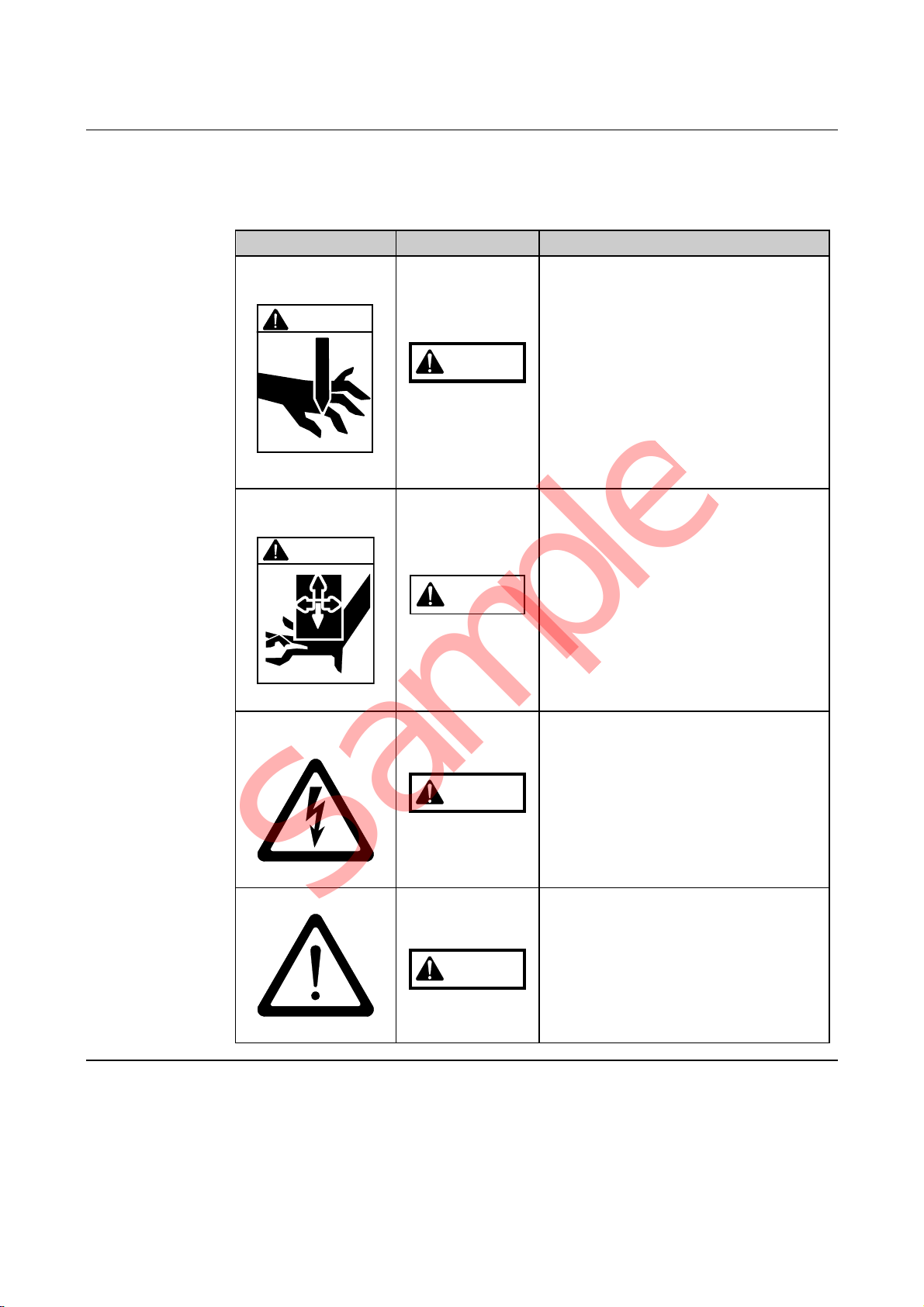
Safety label
Safety labels are affixed to the hazardous sections of the machine. Before
using the machine, verify the label positions and thoroughly understand the
precautions and warning indicated by the safety labels.
Label Hazard Level Meaning of Label
Rotary Blade
Label
WARNING
WARNING
It is possible that your hands and
fingers may be cut by the rotating
blade.
Observe the following precautions
for at least 15 seconds until the
spindle comes to a complete stop:
- Do not place your hands or fingers
near the blade or flange.
- Ensure that the splash cover is
kept closed.
Driving Section
Label
CAUTION
CAUTION
It is possible that yours hands and
fingers may be caught and injured
by the driving section.
While the power is ON, ensure that
the cover is kept closed.
Electrical Shock
Hazard Label
WARNING
Use care to avoid possible electrical
shock hazard.
General Label
WARNING
General caution/warning/danger
label.
Sample

Intro-1
INTRODUCTION
About this manual
This Maintenance Manual explains the maintenance and inspection items and
data setup checkout that are necessary for customer-side maintenance of
Automatic Dicing/Cutting Saws 3*1 Series Models DAD321, DAC351 and
DAD361. This manual is written for the maintenance personnel.
To ensure safety
To ensure safety, be sure to thoroughly read and understand the contents of this
manual before performing maintenance or adjustment. Note that this manual is
based on the software versions of 5.4 series.
When installing or adjusting the machine, be sure to follow the procedures set
forth in this manual.
Be sure that the maintenance should be done by a qualified person who has
completed DISCO's education curriculum (hereinafter referred to as the
maintenance personnel).
Definition of a manager and an operator
This manual defines a manager and an operator as follows:
Category Applicable
personnel Job
Manager Management
representative The person who is responsible for overall
management of machines and operators.
Maintenance
personnel The qualified person who received DISCO
machine maintenance training.
Operator Data maintenance
personnel The qualified person who is responsible
for management of software data of the
machine.
Operator The person who operates the machine to
process workpieces.
Minimum retention period of the maintenance functional parts
Maintenance functional parts required for repair or modification will be
retained by Disco for at least seven years after the B/L date.
Sample

Intro-2
Part replacement
When replacing parts, be sure to use the genuine DISCO brand. If any parts
other than DISCO's genuine parts are used, DISCO shall assume no liability
for any damage of any kind.
When replacing components using the UL-listed parts, be sure to use the UL-
listed parts to be installed.
When replacing any critical parts, consult your nearest DISCO office. If any
critical parts are replaced without consulting DISCO, DISCO shall assume no
liability for any consequences arising therefrom.
Part warranty period
Part warranty period is as follows:
Part Warranty period
Electrical parts having contact points Six months from the B/L date
Consumable parts Not covered
Parts other than the above 12 months from the B/L date
Documentation for this machine
The following five written manuals are provided for this machine.
This manual is the Maintenance Manual indicated by the arrow.
Manual Who should read Contents
Installation Manual Maintenance
personnel Operational procedures for
machine installation and
adjustment
Operation Manual Operator Operational procedures to be
performed by operators
Data Maintenance
Manual Data maintenance
personnel Screen contents for data entry and
data entry procedures
Maintenance
Manual Maintenance
personnel Servicing, inspection and
adjustment procedures to be
performed by customers
Technical
Reference Maintenance
personnel Machine specifications,
circuit diagrams, illustrations and
part lists
Unit notation
International System of Unit is adopted to express any unit. The values in the
parenthesis are reference data. Also, all the pressure values are expressed in
gauge pressure.
Sample

Intro-3
Notation of part number
In this document, the part numbers are shown as follows.
New style part no. Former style part no.
XXXX-XXXXXX-X (YYYYYYYY--Y)
Sample

Intro-4
Section diagram
The diagram and table below show the names and functions of each section.
Operation control
section
Cutting section
Name Function
Cutting Section Cuts workpieces.
Operation Control
Section Keys on the operation panel are used for data entries,
and the function keys perform operations.
Also, the monitor displays operation-related
information and microscope images in accordance
with operation panel manipulation.
Sample
Intro-5
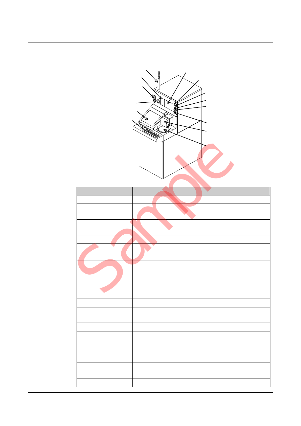
External view
The diagram and the table below show the external view, names and functions
of main constituents.
Operation panel
Splash cover
Vacuum gauge
Flowmeter
Disk drive
Pilot lamp Monitor
Ke
y
switch
POWER lam
p
Maintenance switch
Light intensity
adjustment dial
EMO switch
Chuck table
Microscope
Name Function
Operation Panel Consists of operation control keys.
Splash Cover Prevents water from splashing around during spindle
rotation and functions as a safety device.
Vacuum Gauge Indicates the chuck table vacuum pressure to attract
the workpiece to the chuck table.
Flowmeter Indicates the flow rate of the wheel coolant water.
Disk Drive Functions as an external storage device.
[Optional accessory]
Pilot lamp Indicates the machine operating status with the green
and yellow lamps. If an error occurs, the red lamp
flashes on and off.
Monitor Displays operating information and microscope
images.
POWER Lamp Lights while the power is ON.
Key Switch Used to turn ON and OFF the machine by inserting
and rotating the key.
Maintenance Switch Used by the maintenance personnel.
Light Intensity
Adjustment Dial Adjusts the microscope image light intensity.
EMO Switch Functions as the emergency stop switch. When
pressed, shuts off the electrical power supply.
Microscope Used to view workpieces for alignment and other
purposes.
Chuck Table Used to mount workpieces on it.
Sample
Intro-6
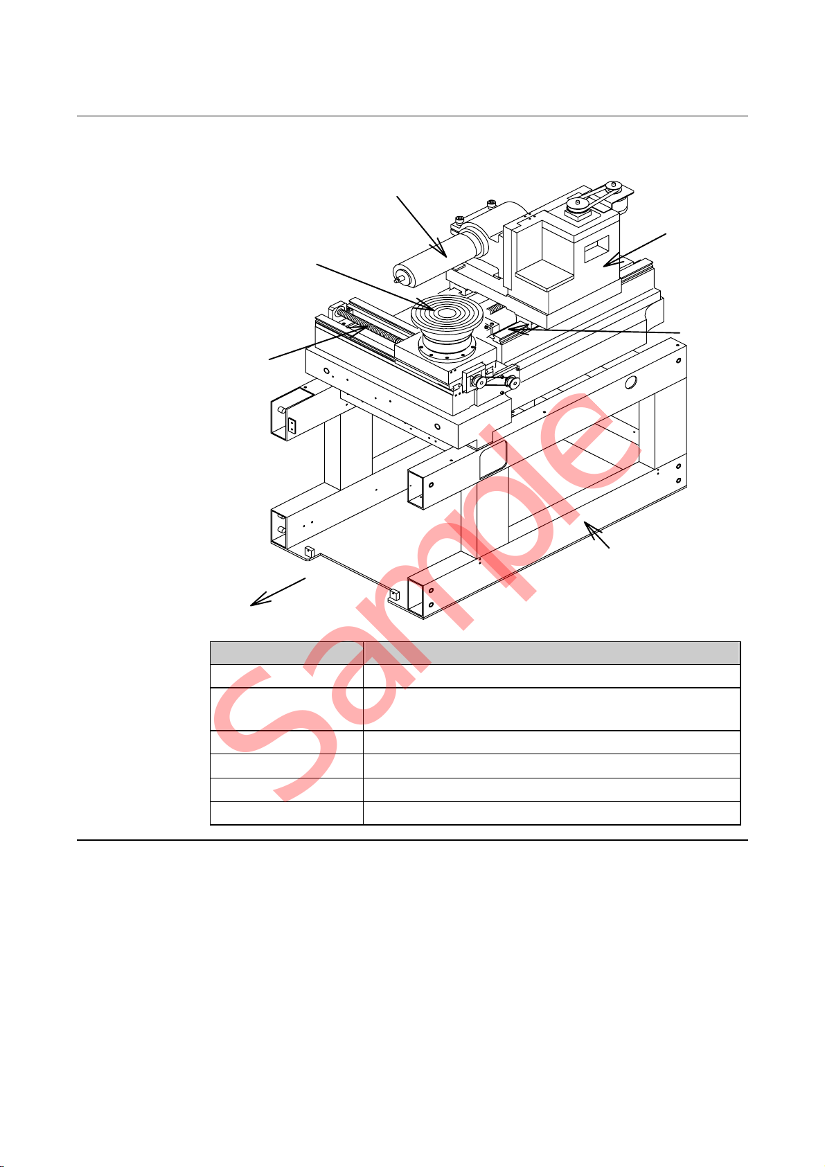
Axis arrangement diagram
The diagram and the table below show axis arrangement, names and functions
of each axis.
X-axis
θ-axis
(except 351)
Spindle axis
Z-axis
Y-axis
Main body frame
Front
Name Function
X-axis Moves the chuck table to the right and the left.
Y-axis Moves the spindle axis and the microscope forward
and backward.
Z-axis Moves the spindle up and down.
θ-axis Rotates the chuck table.
Spindle-axis Rotates a blade at a high speed.
Main Body Frame Supports the machine main body.
Sample

Contents-1
CONTENTS
READ CAREFULLY BEFORE USING THIS MANUAL
INTRODUCTION ................................................Intro-1
CONTENTS ................................................ Contents-1
A. IMPORTANT SAFETY INFORMATION........... A-1
1. General Safety Precautions .................................................................A-2
2. Safety Precautions to Be Observed During Operation..........................A-4
3. Inherently Hazardous Areas and Ways to Avoid Hazards...................A-10
3-1. Inherently HazardousAreas for Operation and Ways toAvoid Hazards...... A-11
3-2. Inherently HazardousAreas for Maintenance
and Ways to Avoid Hazards ......................................................................... A-13
4. EMO Switch.......................................................................................A-16
5. Power Circuit Breaker ........................................................................A-19
6. Interlock Mechanism ..........................................................................A-22
6-1. Interlock Mechanism of Splash Cover..........................................................A-24
6-2. Interlock List ................................................................................................A-30
7. Safety Labels .....................................................................................A-43
8. Critical Component List......................................................................A-48
B. WHOM TO CONTACT IN AN EMERGENCY .. B-1
Sample

Contents-2
CONTENTS
C. MACHINE COMPONENTS
AND FUNCTIONS............................................C-1
1. Machine Outer Cover...........................................................................C-2
2. Axis Section.........................................................................................C-5
2-1. Axis Arrangement ..........................................................................................C-6
2-2. X-axis Section................................................................................................C-7
2-3. Y-axis Section................................................................................................C-9
2-4. Z-axis Section.............................................................................................. C-11
2-5. θ-axis Section..............................................................................................C-13
2-6. Microscope Section .....................................................................................C-16
2-7. Spindle-axis Section ....................................................................................C-17
3. Main Body Section.............................................................................C-21
4. Detection Function.............................................................................C-25
4-1. Personnel Protection ...................................................................................C-26
4-1-1. Safety switch/lock cylinder of the splash cover ..................................C-27
4-2. Machine Protection......................................................................................C-28
4-2-1. Air pressure sensor............................................................................C-29
4-2-2. Flow rate sensor [Optional accessory]...............................................C-30
D. ADJUSTMENT OPERATION...........................D-1
1. Chuck Table Replacement....................................................................D-2
1-1. Chuck Table Classification ...............................................................................D-3
1-2. Chuck Table Replacement ...............................................................................D-6
1-2-1. Precautions for replacing the old type chuck table...............................D-7
1-2-2. Chuck table replacement procedure ..................................................D-12
1-2-2-1. Removing the chuck table ..................................................................................D-14
1-2-2-2. Mounting the chuck table....................................................................................D-16
1-3. Changeover to the New Type Chuck Table ....................................................D-18
2. Flange/Wheel Mount Replacement ....................................................D-19
2-1. Flange Replacement....................................................................................D-20
2-1-1. Removing the flange..........................................................................D-22
Sample

Contents-3
CONTENTS
2-1-2. Mounting the flange............................................................................D-24
2-2. Wheel Mount Replacement .........................................................................D-26
2-2-1. Removing the wheel mount................................................................D-28
2-2-2. Mounting the wheel mount.................................................................D-30
3. Sensor Adjustment.............................................................................D-32
3-1. Air Pressure Sensor Adjustment..................................................................D-33
3-1-1. Removing the outer covers ................................................................D-34
3-1-2. Adjusting the air pressure sensor.......................................................D-35
E. ENGINEERING MAINTENANCE
OPERATIONS.................................................. E-1
1. Calling up ENGINEERING MAINTENANCE Screen ............................E-2
2. Wheel Mount/Flange Conditioning .......................................................E-5
2-1. Movement in Conditioning............................................................................. E-6
2-1-1. Flange conditioning.............................................................................. E-7
2-1-2. Wheel mount conditioning....................................................................E-8
2-2. Executing Conditioning..................................................................................E-9
2-2-1. Replacing the chuck table.................................................................. E-11
2-2-2. Verifying CONDITIONING screen data..............................................E-12
2-2-3. Executing conditioning....................................................................... E-15
2-2-4. Checking the end face accuracy........................................................ E-19
2-2-5. Completion of conditioning................................................................. E-20
3. Axis Operation Check.........................................................................E-21
4. Sensor/Solenoid Valve Check............................................................E-25
4-1. Digital I/O Check..........................................................................................E-26
4-2. Axis Sensor Check ......................................................................................E-29
5. Customizing Setting...........................................................................E-33
5-1. Setting on USER DEFINE DATA1 Screen ..................................................E-34
5-2. Setting on USER DEFINE DATA2 Screen ..................................................E-43
5-3. Setting Password......................................................................................... E-47
5-4. Setting on HAIRLINE ADJUSTMENT Screen..............................................E-50
6. Log Viewer.........................................................................................E-53
7. Maker Data.........................................................................................E-61
Sample

Contents-4
CONTENTS
F. TROUBLESHOOTING ......................................F-1
1. Remedies for Problems Invoking No Error Code Indication
- Problems at Power ON - ....................................................................F-2
1-1. Power Receiving Lamp Problems.................................................................. F-3
1-2. Main Circuit Breaker Problems...................................................................... F-4
1-3. Main Power Supply Problems........................................................................ F-5
1-4. POWER Lamp (Power-On Lamp) Problems.................................................. F-7
1-5. Monitor Problems........................................................................................... F-8
1-6. Microscope Light Source Problems............................................................. F-10
1-7. EMO Switch Problems................................................................................. F-12
2. Remedies for Problems Invoking Error Code Indication .....................F-13
2-1. Error Code Classification............................................................................. F-14
2-2. Error Code List ............................................................................................ F-15
2-3. Error Remedies ........................................................................................... F-17
2-4. Axis-Related Error Remedies...................................................................... F-57
G. MAINTENANCE AND
REGULAR INSPECTION.................................G-1
1. Maintenance Whose Interval Differs Depending on
theUseConditionsoftheDevice.............................................................G-3
1-1. Cleaning the Non-contact Setup Sensor
(Detection Surface) [Optional Accessory].......................................................G-4
1-1-1. Calling up the NON-CONTACT SENSOR CLEAN screen ...................G-5
1-1-2. Cleaning the non-contact setup sensor................................................G-7
1-1-3. Cleaning the non-contact setup sensor with abrasives
[Optional accessory].............................................................................G-9
1-1-4. Adjusting the non-contact setup amplifier...........................................G-11
1-1-5. Completion of cleaning the non-contact setup sensor........................G-15
1-2. Cleaning the Blade Breakage Detector Sensor [Optional Accessory]..........G-16
1-2-1. Removing the blade breakage detector .............................................G-17
1-2-2. Cleaning the blade breakage detector sensor....................................G-19
1-2-3. Adjusting the amplifier of blade breakage detector ............................G-22
1-2-4. Completion of cleaning the blade breakage detector sensor .............G-24
1-3. Cleaning the Spindle....................................................................................G-25
Sample

Contents-5
CONTENTS
1-3-3. Cleaning the spindle main body.........................................................G-30
1-3-4. Cleaning the edge of the spindle........................................................G-31
1-3-5. Completion of spindle cleaning ..........................................................G-32
FYI: Possible problems of the spindle due to stains.....................................G-32
2. Maintenance and Inspection to Be Done Every Day...........................G-33
2-1. Maintenance and Inspection Before Turning ON the Power........................G-34
2-2. Maintenance and InspectionAfter Turning ON the Power...........................G-35
3. Maintenance to Be Performed at 7-Day
(Recommended) Intervals..................................................................G-36
3-1. Cleaning the Cutting Room..........................................................................G-37
3-1-1. Water case outer area cleaning..........................................................G-38
3-1-2. Water case inside cleaning ................................................................G-40
3-1-3. Completion of cleaning the cutting room............................................G-41
4. Maintenance to Be Performed at 30-Day
(Recommended) Intervals..................................................................G-42
4-1. Conditioning the Flange...............................................................................G-42
5. Maintenance to Be Performed at 90-Day
(Recommended) Intervals..................................................................G-43
5-1. Cleaning the Electrical box Filter
(in case this machine is used outside the cleanroom)..................................G-44
6. Maintenance to Be Performed at 183-Day
(Recommended) Intervals..................................................................G-49
6-1. Conditioning the Wheel Mount.....................................................................G-49
6-2. Greasing theAxes and Ball-Bearing Leadscrews........................................G-50
6-2-1. Greasing the X-axis............................................................................G-51
6-2-1-1. Cleaning the rail and ball-bearing leadscrew .....................................................G-52
6-2-1-2. Greasing the left side of the X-axis.....................................................................G-54
6-2-1-3. Greasing the right side of the X-axis ..................................................................G-56
6-2-1-4. Completion of greasing the X-axis......................................................................G-58
6-2-2. Greasing the Y-axis............................................................................G-59
6-2-2-1. Greasing the rear of the Y-axis...........................................................................G-60
6-2-2-2. Greasing the front of the Y-axis ..........................................................................G-63
6-2-2-3. Completion of greasing the Y-axis......................................................................G-66
6-2-3. Greasing the Z-axis............................................................................G-67
6-2-3-1. Greasing the Z-axis ............................................................................................G-68
6-2-3-2. Completion of greasing the Z-axis......................................................................G-71
Sample

Contents-6
CONTENTS
6-3. Cleaning the Spindle Coolant Water Path....................................................G-72
6-3-1. Cleaning the spindle coolant water path ............................................G-73
6-3-2. Completion of cleaning the spindle coolant water path ......................G-75
7. Maintenance to Be Performed at 365-Day
(Recommended) Intervals..................................................................G-76
7-1. Adjusting the Timing Belt.............................................................................G-77
7-1-1. Adjusting the X-axis timing belt..........................................................G-78
7-1-2. Adjusting the Z-axis timing belt ..........................................................G-81
7-2. Cleaning the Vacuum Ejector ......................................................................G-84
7-3. Cleaning the Electrical box Filter
(in case this machine is used inside the cleanroom)....................................G-87
H. CONSUMABLE PARTS REPLACEMENT.......H-1
1. Consumables to Be Replaced at 365-Day
(Recommended) Intervals....................................................................H-2
1-1. Replacing the Filters for Air............................................................................H-3
1-2. Replacing the Halogen Lamp ........................................................................H-6
1-3. Replacing the Spindle Carbon Brush.............................................................H-9
1-4. Replacing the Waterproof Sponge...............................................................H-12
1-5. Replacing the Spindle Waterproof Plate/Ring..............................................H-14
1-5-1. Removing the blade/wheel cover.......................................................H-15
1-5-2. Replacing the spindle waterproof plate/ring.......................................H-17
2. Consumables to Be Replaced at 700-Day
(Recommended) Intervals..................................................................H-19
2-1. Replacing the Operation Panel Overlay Sheet............................................H-20
2-2. Replacing the Flowmeter (Tap Water Line)..................................................H-22
2-2-1. Removing the machine outer cover....................................................H-23
2-2-2. Replacing the flowmeter.....................................................................H-25
2-2-3. Completion of replacing the flowmeter...............................................H-26
2-3. Replacing the Spindle/Wheel Coolant Water Flow Rate Sensor
[Optional accessory].....................................................................................H-27
2-3-1. Removing the machine outer cover....................................................H-28
2-3-2. Replacing the flow rate sensor...........................................................H-30
2-3-3. Completion of replacing the flow rate sensor.....................................H-31
Sample

Contents-7
CONTENTS
2-4. Replacing the Solenoid Valve......................................................................H-32
2-4-1. Removing the machine outer cover....................................................H-33
2-4-2. Replacing the solenoid valve..............................................................H-35
2-4-3. Completion of replacing the solenoid valve........................................H-37
3. Consumables to Be Replaced at 1000-Day
(Recommended) Intervals..................................................................H-38
3-1. Replacing the Chuck Table Waterproof Cover
/Chuck Table O-ring/Bellows........................................................................H-39
3-1-1. Removing the chuck table..................................................................H-40
3-1-2. Replacing the waterproof cover/O-ring/bellows..................................H-41
3-1-3. Completion of replacing the waterproof cover/ O-ring/bellows...........H-44
3-2. Replacing the Chuck Table Center Ring......................................................H-45
I. DATA SHEET.......................................................I-1
1. Noise Level ........................................................................................... I-2
CHECK SHEET 1 - MAINTENANCE
AND REGULAR INSPECTION -..........Appendix-1
CHECK SHEET 2 - CONSUMABLE
PARTS REPLACEMENT - ...................Appendix-2
INDEX...............................................................Index-1
ADDRESS LIST
IN AN EVENT OF AN ACCIDENT
Sample

A-1
A. IMPORTANT SAFETY INFORMATION
Contents of this chapter
This chapter describes various precautions to assure safety in the operation and
safety protective functions employed in this machine.
Section
No. Title Contents
1General Safety Precautions - Safety precautions to be
understood before operation
- Safety precautions to be
observed during operation
2Safety Precautions to Be
Observed During Operation - Safety precautions that operators
should understand before
operation
- Safety precautions that operators
should observe during
performing any work
3Inherently Hazardous Areas
and Ways to Avoid Hazards - Potentially hazardous sections
and the ways to avoid hazards
4EMO Switch - Construction of the EMO
(Emergency OFF) switch
- Function of the EMO switch
5Power Circuit Breaker - Construction of the power circuit
breaker
- Function of the power circuit
breaker
6Interlock Mechanism - Construction of the interlock
mechanism
- Function of the interlock
mechanism
7Safety Labels - Type of safety labels
- Affixing positions of safety
labels
8Critical Component List - List of critical components used
in the machine
Sample
A-2
1. General Safety Precautions
General safety precautions
This section describes the general safety precautions that should be understood
before operation and observed during operation.
CAUTION
Machine installation environment
Comply with the recommended machine installation conditions
(such as room temperature, humidity or temperature of spindle
coolant water and wheel coolant water). If the machine is installed in
an environment that does not conform to the installation conditions
recommended by DISCO, rust formation may occur due to moisture
condensation or other factor, thereby adversely affecting the cutting
accuracy.
For the recommended environmental conditions, see section C-1 of
Installation Manual, [Installation Specifications and Environment].
NOTICE
- Responsibility for instructing workers
Instruct the operators and maintenance personnel to read the
safety precautions set forth in the Maintenance Manual before
proceeding to work. Also, if the operator performs various tasks,
direct them to read the points of note concerning the safety given in
the respective manuals.
The written instructions for this machine are Installation Manual,
Operation Manual, Data Maintenance Manual, Maintenance
Manual and Technical Reference.
- Responsibility for instructing workers who don't seem to understand
the points of note
For the workers who don't seem to understand what is given in the
manuals, explain the safety items described in this chapter so that
they understand what the points mean.
- Regular inspection
The machine must be inspected on a regular basis.
If any accidents occur while an appropriate regular inspection
program is not adhered to, DISCO is not responsible for the results.
- Maintenance personnel
Maintenance must be conducted by qualified personnel who have
received the maintenance training.
- Proper installation of safety device
If the covers or other parts with safety interlocks are broken,
immediately stop the machine and repair broken parts.
Sample

A-3
General safety precautions (Continued)
NOTICE
- Air exhaust, water drainage and contamination control
Since harmful substance may be generated depending on the
cutting work type and machining characteristics, air exhaust, water
drainage and contamination control/disposal must be properly
completed in compliance with applicable environmental protection
codes.
- Exhaust sampling port
The machine requires an exhaust operation. When measuring the
exhaust for the machine to fulfill legal requirements, use the
sampling port, which is provided at the location indicated below.
(connection port: Rc (PT) 1/8 female)
View [A]
Duct
[A]
Sampling port
[Rc(PT)1/8 female]
- Facility side interlock connection terminal (Special user
specification)
To permit the facility side to provide air exhaust and water drainage
interlock, the machine is equipped with air exhaust and water
drainage reservoir tank interlock connection terminals.
When connecting these terminals to the facility side interlock
system, contact your nearest DISCO office.
- Machine relocation/disposal
In the case of relocation or disposal of the machine, the
presentation of detailed precautionary notes and the management
of new installation site data will be done by DISCO.
If you want to relocate or disposal the machine, contact your
nearest DISCO office or DISCO service office.
Sample
Other manuals for DAD321
1
This manual suits for next models
2
Table of contents
Other DISCO Saw manuals


Popular Saw manuals by other brands


Makita
Makita BPB180 technical information

PEUGEOT
PEUGEOT EnergySaw-185ASP manual

Parkside
Parkside PDKS 120 A2 operation and safety notes original operating instructions

Makita
Makita SP6000 instruction manual

Woodtec
Woodtec XW032 instruction manual

AEG Powertools
AEG Powertools PSD18B-254X Original instructions


