DISCO DAD321 User manual

2006-08
DATA MAINTENANCE MANUAL
Automatic Dicing/Cutting Saws
DAD321
DAC351
DAD361
DAD341
DAD381
SOFTWARE VERSION 5.4 SERIES
UHESDE*054C
Copyright of this document is owned by Disco Corporation ("Disco").
No part of this document may be copied or reproduced in any form
or by any means, without the express written permission of Disco.
Also, this document may not be disclosed or transferred to third
parties.
This document is printed on recyclable Lint-Free paper.
- The blue paper is recyclable as used paper just like plain paper.
- The cover paper and adhesive portions are non-recyclable.
(Remove the cover and adhesive portions before recycling.
Recycle the blue paper only.)
Sample

READ CAREFULLY BEFORE USING THIS
MANUAL
Introduction
This machine is a dicing saw for cutting silicon wafers and glass circuit boards
(workpieces, hereafter).
It has the rotary sections which rotate at high speed, the high-voltage sections
which may cause electric shock hazards and the drive sections which may
catch the operator's body and clothing.
If the machine is not properly operated, safety hazards may cause serious
injury or death.
Read before using the machine
Before using the machine, thoroughly read this manual and follow the
instructions set forth in this manual.
To assure safety in the operation and maintenance of the machine, it is
important that you know the location of potential safety hazards. It is difficult
for DISCO to foresee each and every potential safety hazard. However, this
manual carries various precautionary notes and warnings to indicate the
presence of all foreseeable potential safety hazards. For increased safety
assurance, it is therefore essential that you observe all the precautions and
other relevant instructions set forth in this manual.
If you modify the machine without prior consent of DISCO or repair it in a
manner not stated in this manual, the safety assurance features of the machine
may be seriously affected.
Never attempt to modify or repair the machine in a manner not approved by
DISCO.
Sample

Hazard level
The safety precautions set forth in this document are classified into DANGER,
WARNING and CAUTION categories which represent three degree of hazards
latent in the machine. These categories are defined as detailed below in
accordance with the seriousness and probability level of the hazard. In addition
to the above three safety precaution levels, NOTICE is used to give safety
usage instructions to the user.
Before using the machine, be sure to read and understand all the associated
safety precautions set forth in the manual.
Hazard levels are classified as follows:
DANGER
DANGER indicates an imminently hazardous situation
which, if not avoided, will result in death or serious
injury.
This symbol is used for the incident in which the
damage is serious and there is high probability of
occurrence.
WARNING
WARNING indicates a potentially hazardous situation
which, if not avoided, could result in death or serious
injury.
This symbol is used for the incident in which the
damage is serious but there is not high probability of
occurrence.
CAUTION
CAUTION indicates a potentially hazardous situation
which, if not avoided, may result in minor or moderate
injury.
This symbol is used for the incident in which the
damage is slight and there is not high probability of
occurrence.
CAUTION
If you cannot avoid the incident in question, an accident
of physical damage may be caused.
NOTICE
Indicates the safe way of using the machine as well as
precautions to avoid accidents that may result in
property damage.
Sample

Safety label
Safety labels are affixed to the hazardous sections of the machine. Before
using the machine, verify the label positions and thoroughly understand the
precautions and warning indicated by the safety labels.
Label Hazard Level Meaning of Label
Rotary Blade
Label
WARNING
WARNING
It is possible that your hands and
fingers may be cut by the rotating
blade.
Observe the following precautions
for at least 15 seconds for
321/351/361 or 20 seconds for
341/381 until the spindle comes to
a complete stop:
- Do not place your hands or fingers
near the blade or flange.
- Ensure that the splash cover is
kept closed.
Driving Section
Label
CAUTION
CAUTION
It is possible that yours hands and
fingers may be caught and injured
by the driving section.
While the power is ON, ensure that
the cover is kept closed.
Electrical Shock
Hazard Label
WARNING
Use care to avoid possible electrical
shock hazard.
General Label
WARNING
General caution/warning/danger
label.
Sample

Intro-1
INTRODUCTION
About this manual
This Data Maintenance Manual describes the screen details related to certain
operations and procedures for setting operational data and machine operation
data concerning Automatic Dicing/Cutting Saws 3*1 Series Models DAD321,
DAC351, DAD361, DAD341 and DAD381 for data maintenance personnel.
To ensure safety
To ensure safety, be sure to thoroughly read and understand the contents of this
manual before starting any operation of the machine. Note that this manual is
based on the software version of 5.4 series.
When performing data setup or operation related to data, be sure to follow the
procedures set forth in this manual.
Definition of a manager and an operator
This manual defines a manager and an operator as follows:
Category Applicable
Personnel Job
Manager Management
representative The person who is responsible for overall
management of machines and operators.
Maintenance
personnel The qualified person who received DISCO
machine maintenance training.
Operator Data maintenance
personnel The qualified person who is responsible
for management of software data of the
machine.
Operator The person who operates the machine to
process workpieces.
Sample

Intro-2
Documentation for this machine
The following five written manuals are provided for 3*1 series machine.
This manual is the Data Maintenance Manual shaded in the list below.
Manual Who should read Contents
Installation Manual Maintenance
personnel Operational procedures for
machine installation and
adjustment
Operation Manual Operator Operational procedures to be
performed by operators
Data
Maintenance
Manual
Data
maintenance
personnel
Screen contents for data entry
and data entry procedures
Maintenance
Manual Maintenance
personnel Servicing, inspection and
adjustment procedures to be
performed by customers
Technical
Reference Maintenance
personnel Machine specifications,
circuit diagrams, illustrations and
part lists
Unit notation
International System of Unit is adopted to express any unit. The values in the
parenthesis are reference data. Also, all the pressure values are expressed in
gauge pressure.
Sample

Intro-3
Section Diagram
The diagram and the table below show names and functions of each
component.
Operation control
section
[321/351/361]
Cutting section
[341/381]
Cutting section
Operation control
section
Name Function
Cutting Section Cuts workpieces.
Operation Control
Section Keys on the operation panel are used for data entries,
and the function keys perform operations.
Also, the monitor displays operation-related
information and microscope images in accordance
with operation panel manipulation.
Sample

Intro-4
External View [321/351/361]
The diagram and the table below show the external view, names and functions
of main constituents.
Operation panel
Splash cover
Vacuum gauge
Flowmeter
Disk drive
Pilot lamp Monitor
Key switch
POWER lamp
Maintenance switch
Light intensity
adjustment dial
EMO switch
Chuck table
Microscope
Name Function
Operation Panel Consists of operation control keys.
Splash Cover Prevents water from splashing around during spindle
rotation and functions as a safety device.
Vacuum Gauge Indicates the chuck table vacuum pressure to attract
the workpiece to the chuck table.
Flowmeter Indicates the flow rate of the wheel coolant water.
Disk Drive Functions as an external storage device.
[Option accessory]
Pilot Lamp Indicates the machine operating status with the green
and yellow lamps. If an error occurs, the red lamp
flashes on and off.
Monitor Displays operating information and microscope
images.
POWER Lamp Lights while the power is ON.
Key Switch Used to turn ON and OFF the machine by inserting
and rotating the key.
Maintenance Switch Used by the maintenance personnel.
Light Intensity
Adjustment Dial Adjusts the microscope image light intensity.
EMO Switch Functions as the emergency stop switch. When
pressed, shuts off the electrical power supply.
Microscope Used to view workpieces for alignment and other
purposes.
Chuck Table Used to mount workpieces on it.
Sample

Intro-5
External View [341/381]
The diagram and the table below show the external view, names and functions
of main constituents.
POWER lamp
Disk drive
Key switch
Maintenance switch
Light intensity
adjustment dial
POWER
ON
OFF START
AXIS
LOCK AXIS
RELEASE
REMOTE
LAMP
VOLUME
MANUAL
Operation panel
Splash cover
Vacuum gauge
Flowmeter
Pilot lamp
Monitor
EMO switch
Chuck table
Microscope
Name Function
Chuck Table Used to mount workpieces on it.
EMO Switch Functions as the emergency stop switch. When
pressed, shuts off the electrical power supply.
Operation Panel Consists of operation control keys.
Vacuum Gauge Indicates the chuck table vacuum pressure to attract
the workpiece to the chuck table.
Flowmeter Indicates the flow rate of the wheel coolant water.
Splash Cover Prevents water from splashing around during spindle
rotation and functions as a safety device.
Microscope Used to view workpieces for alignment and other
purposes.
Monitor Displays operating information and microscope
images.
Pilot Lamp Indicates the machine operating status with the green
and yellow lamps. If an error occurs, the red lamp
flashes on and off.
Disk Drive Functions as an external storage device.
[341:Optional accessory/381:Standard part]
Key Switch Used to turn ON and OFF the machine by inserting
and rotating the key.
POWER Lamp Lights while the power is ON.
Maintenance Switch Used by the maintenance personnel.
Light Intensity
Adjustment Dial Adjusts the microscope image light intensity.
Sample
Intro-6
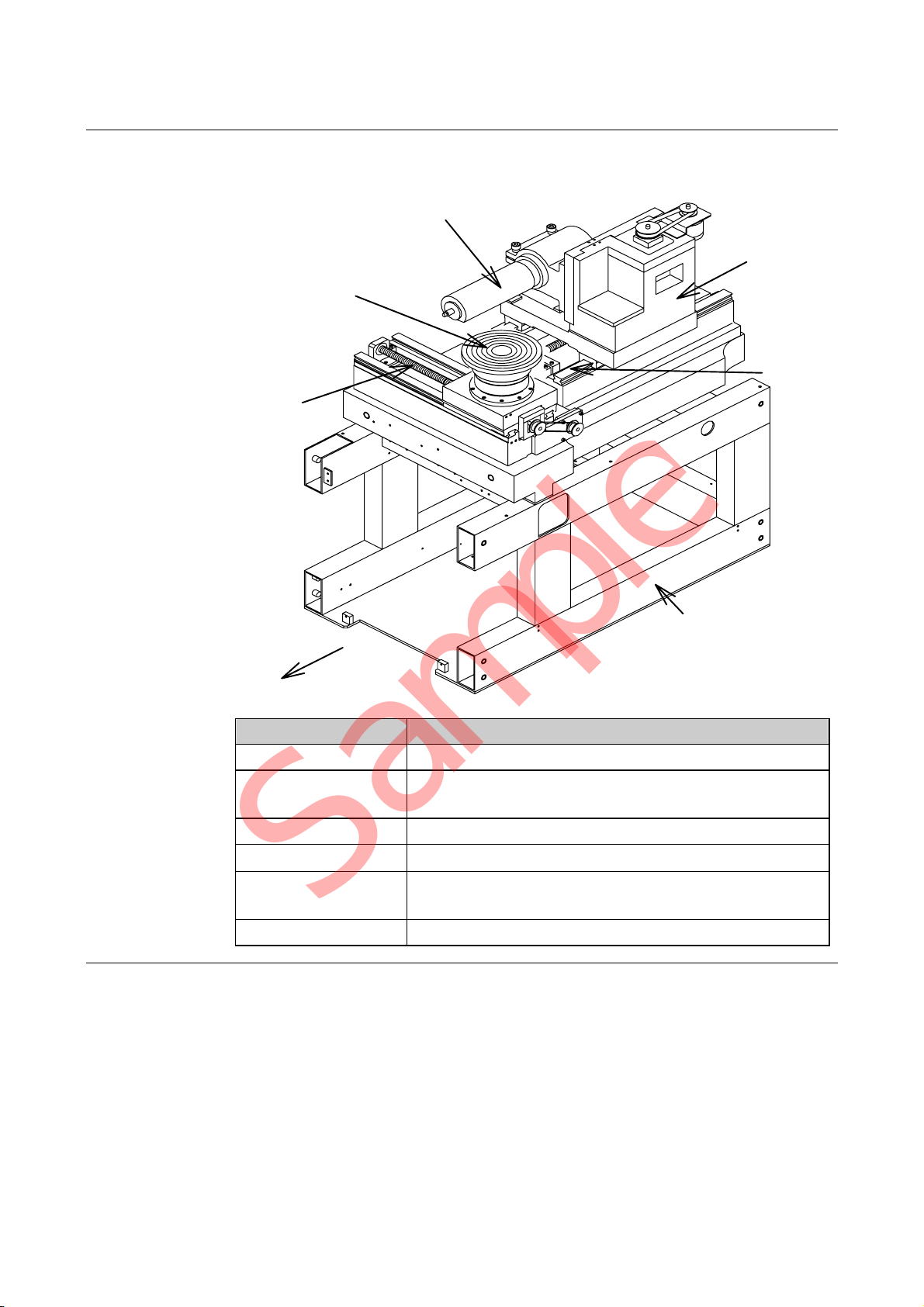
Axis Arrangement Diagram [321/351/361]
The diagram and the table below show axis arrangement, names and functions
of each axis.
X-axis
θ
-axis
(except 351)
Spindle axis
Z-axis
Y-axis
Main body frame
Front
Name Function
X-axis Moves the chuck table to the right and the left.
Y-axis Moves the spindle shaft and the microscope forward
and backward.
Z-axis Moves the spindle up and down.
θ-axis Rotates the chuck table.
Spindle Shaft
Section Rotates a blade at a high speed.
Main Body Frame Supports the machine main body.
Sample

Intro-7
Axis Arrangement Diagram [341/381]
The diagram and the table below show axis arrangement, names and functions
of each axis.
X-axis
θ
-axis
Spindle axis
Z-axis
Y-axis
Main body frame
Front
Electrical system
section
Name Function
X-axis Moves the chuck table to the right and the left.
Y-axis Moves the spindle shaft and the microscope forward
and backward.
Z-axis Moves the spindle up and down.
θ-axis Rotates the chuck table.
Electrical System
Section Controls machine operation.
Spindle Shaft
Section Rotates a blade at a high speed.
Main Body Frame Supports the machine main body.
Sample

Contents-1
CONTENTS
READ CAREFULLY BEFORE USING THIS MANUAL
INTRODUCTION ................................................Intro-1
CONTENTS ................................................ Contents-1
A. IMPORTANT SAFETY INFORMATION........... A-1
1. General Safety Precautions .................................................................A-2
2. Safety Precautions to Be Observed During Operation..........................A-5
3. Inherently Hazardous Areas and Ways to Avoid Hazards.....................A-9
4. EMO Switch.......................................................................................A-13
5. Power Circuit Breaker ........................................................................A-16
6. Interlock Mechanism ..........................................................................A-18
6-1. Interlock Mechanism of Splash Cover..........................................................A-20
7. Safety Labels .....................................................................................A-22
B. WHOM TO CONTACT IN AN EMERGENCY .. B-1
C. GENERAL DESCRIPTION OF DATA SCREEN
OPERATIONS..................................................C-1
1. Data Screen Structure..........................................................................C-2
2. Operation Panel.................................................................................C-18
2-1. Operation Panel Key Layout........................................................................C-19
Sample

Contents-2
CONTENTS
2-2. Names and Functions of Touch-Activated Keys...........................................C-20
2-2-1. Keys for start/stop and alarm cancel and Z-EM key...........................C-21
2-2-2. Single-function keys...........................................................................C-22
2-2-3. Keys to setup, call and edit data ........................................................C-23
2-2-4. Axis operation keys............................................................................C-25
2-2-5. Auxiliary key.......................................................................................C-28
D. DATA MAINTENANCE.....................................D-1
1. Data Setup/Operation Screens Used by Operators..............................D-3
1-1. MAIN MENU Screen [Screen 0.0]..................................................................D-5
1-2. Cutting Related Screens................................................................................D-9
1-2-1. Auto cutting related screens...............................................................D-10
1-2-1-1. AUTO CUTTING screen [screen 1.0] --- DAD mode ---.....................................D-11
1-2-1-2. DAC CUT screen [screen 1.0] --- DAC mode ---................................................D-13
1-2-1-3. STATUS OF CUTTING screen --- DAD mode --- ...............................................D-15
1-2-1-4. STATUS OF CUTTING screen --- DAC mode --- ...............................................D-17
1-2-1-5. BLADE INFORMATION 2 screen.......................................................................D-19
1-2-2. Semi auto cutting related screens......................................................D-22
1-2-2-1. SEMI AUTO CUT screen [screen 2.0] --- DAD mode ---....................................D-23
1-2-2-2. SINGLE CHANNELALIGNMENT screen...........................................................D-25
1-3. Screens Related to Correction during Cutting .............................................D-26
1-3-1. STOP CORRECTION screen (cutting correction screen) ..................D-27
1-3-2. KERF CHECK DATA 1 screen (stop correction process)...................D-29
1-3-3. KERF CHECK DATA 2 screen (stop correction process)
[optional accessory]............................................................................D-31
1-3-4. BLADE REPLACEMENT screen (stop correction process)
[optional accessory]............................................................................D-34
1-3-5. LIGHTADJUSTMENT screen ---341/381 only---................................D-35
1-4. Device Data Related Screens......................................................................D-36
1-4-1. Copying, deleting or renaming the device data..................................D-37
1-4-1-1. DEVICE DATA LIST screen [screen 4.0]............................................................D-38
1-4-1-2. Entering the data password................................................................................D-40
1-4-1-3. DEVICE DATA COPY screen .............................................................................D-41
1-4-1-4. DEVICE DATA DELETE screen..........................................................................D-42
1-4-1-5. DEVICE DATA RENAME screen........................................................................D-43
Sample

Contents-3
CONTENTS
1-4-2. Device data related screens --- DAD mode ---...................................D-45
1-4-2-1. DEVICE DATA 1 screen [screen 4.2]..................................................................D-46
1-4-2-2. DEVICE DATA 2 screen [screen 4.3]..................................................................D-49
1-4-2-3. DEVICE DATA 3 screen [screen 4.4]..................................................................D-51
1-4-2-4. KERF CHECK FUNCTION PARAMETER screen [screen 4.7]..........................D-53
1-4-2-5. PRECUT DATA (auto control) screen [screen 6.1.1]..........................................D-57
1-4-2-6. PRECUT DATA (number of lines control) screen [screen 6.1.1] ........................D-59
1-4-2-7. PRECUT DATA (length control) screen [screen 6.1.1] .......................................D-61
1-4-3. Device data related screens --- DAC mode ---...................................D-63
1-4-3-1. DEVICE DATA 1 screen [screen 4.2]..................................................................D-64
1-4-3-2. DEVICE DATA2 screen [screen 4.3] (normal program).....................................D-67
1-4-3-3. DEVICE DATA3 screen [screen 4.4] (normal program).....................................D-69
1-4-3-4. DEVICE DATA 2 screen [screen 4.3] (special program).....................................D-70
1-4-3-5. DEVICE DATA 3 screen [screen 4.4] (special program).....................................D-75
1-4-3-6. SIMULATION screen..........................................................................................D-80
1-5. Blade Maintenance Related Screens...........................................................D-81
1-5-1. BLADE MAINTENANCE screen [screen 5.0].....................................D-82
1-5-2. Blade replacement related screens....................................................D-83
1-5-2-1. BLADE REPLACEMENT screen [screen 5.1]....................................................D-84
1-5-2-2. BLADE SELECTOR screen [screen 5.1.5].........................................................D-86
1-5-3. ADJUSTMENT OF B.B.D.(Blade Breakage Detector) screen [screen 5.2]
[optional accessory]............................................................................D-88
1-5-4. Hairline alignment related screens.....................................................D-89
1-5-4-1. HAIRLINE ALIGNMENT screen [screen 5.5]......................................................D-90
1-5-4-2. HAIRLINE ALIGNMENT IN PROGRESS screen [screen 5.5.1] ........................D-92
1-5-5. BLADE LIFE/WEAR INFORMATION screen [screen 5.6]..................D-93
1-6. Dressing Related Screens...........................................................................D-95
1-6-1. About dressing...................................................................................D-96
1-6-2. DRESS DATA screen [screen 5.4]......................................................D-97
1-6-3. DRESS IN PROGRESS screen [screen 5.4.1]...................................D-99
1-7. Setup Related Screens..............................................................................D-101
1-7-1. SETUP screen [screen 5.3]..............................................................D-102
1-7-2. CHUCK TABLE SETUP screen [screen 5.3.1].................................D-103
1-7-3. POINTED CHUCK TABLE SETUP screen [screen 5.3.2]................D-105
1-7-4. NON-CONTACT SETUP screen [screen 5.3.3]
[optional accessory]..........................................................................D-107
1-7-5. SENSOR CALIBRATION SETUP screen [screen 5.3.4]
[optional accessory]..........................................................................D-109
1-7-6. NON-CONTACT SENSOR CLEAN screen [screen 5.8]
[optional accessory]...........................................................................D-111
Sample

Contents-4
CONTENTS
1-8. Error Recovery Related Screens............................................................... D-112
1-8-1. ERROR RECOVERY (KERF CHECK) screen
[optional accessory].......................................................................... D-113
1-8-2. ERROR RECOVERY (B.B.D) screen [optional accessory].............. D-116
1-8-3. ERROR RECOVERY (SETUP) screen [optional accessory]............ D-118
2. Cutting Data Setup...........................................................................D-121
2-1. Cutting Function...........................................................................................D-122
2-1-1. Cutting shape...................................................................................D-123
2-1-2. Cutting mode....................................................................................D-124
2-1-2-1. A cutting mode..................................................................................................D-125
2-1-2-2. B cutting mode..................................................................................................D-126
2-1-2-3. AS cutting mode ...............................................................................................D-127
2-1-2-4. BS cutting mode ...............................................................................................D-128
2-1-2-5. B ZKEEP cutting mode ..................................................................................D-129
2-1-2-6. BS ZKEEP cutting mode................................................................................D-129
2-1-2-7. A UP/AS UP cutting mode...........................................................................D-130
2-1-3. Blade wear compensation function ..................................................D-131
2-1-3-1. About blade wear compensation (Z-axis auto-down).......................................D-132
2-1-3-2. Blade wear compensation precautions.............................................................D-133
2-2. Cutting Data Setup Example --- DAD Mode ---..........................................D-136
2-2-1. Cutting data setup example 1
--- A/B/A UP/B ZKEEP cutting mode ---............................................D-137
2-2-1-1. Description of cutting data <example 1>..........................................................D-138
2-2-1-2. Procedures for data setup <example 1> ..........................................................D-142
2-2-2. Cutting data setup example 2
--- AS/BS/AS UP/BS ZKEEP cutting mode ---................................D-149
2-2-2-1. Description of cutting data <example 2>..........................................................D-150
2-2-2-2. Procedures for data setup <example 2> ..........................................................D-154
2-2-3. Cutting data setup example 3
--- AS cutting mode/ multiple indexing/rectangular cutting ---...........D-159
2-2-3-1. Description of cutting data <example 3>..........................................................D-160
2-2-3-2. Procedures for data setup <example 3> ..........................................................D-164
2-2-4. Cutting data setup example 4
--- AS cutting mode/multi-channel/hexagonal-shaped chip ---..........D-169
2-2-4-1. Description of cutting data <example 4>..........................................................D-170
2-2-4-2. Procedures for data setup <example 4> ..........................................................D-174
2-2-5. Device data registration....................................................................D-180
2-3. Cutting Data Setup Example --- DAC Mode ---..........................................D-181
2-3-1. Cutting data setup example 5 --- A cutting mode ---.........................D-182
2-3-1-1. Description of cutting data <example 5>..........................................................D-183
2-3-1-2. Procedures for data setup <example 5> ..........................................................D-185
Sample

Contents-5
CONTENTS
2-3-2. Cutting data setup example 6
--- A cutting mode/normal program/alternately using two different index
and amount left uncut --- ..................................................................D-192
2-3-2-1. Description of cutting data <example 6>..........................................................D-193
2-3-2-2. Procedures for data setup <example 6> ..........................................................D-195
2-3-3. Cutting data setup example 7
--- A cutting mode/normal program/ multiple indexing
/multi-level cutting ---........................................................................D-200
2-3-3-1. Description of cutting data <example 7>..........................................................D-201
2-3-3-2. Procedures for data setup <example 7> ..........................................................D-204
2-3-4. Cutting data setup example 8
--- A cutting mode/special program ---..............................................D-209
2-3-4-1. Description of cutting data <example 8>..........................................................D-210
2-3-4-2. Procedures for data setup <example 8> ..........................................................D-213
2-3-4-3. Special mode explanation screen [HELP screen].............................................D-218
3. Setup Data.......................................................................................D-221
3-1. Specifying the Setup Data .........................................................................D-222
3-2. Outline of Chuck Table Setup Operation....................................................D-230
3-3. Outline of Non-contact Setup Operation [Optional Accessory] ..................D-232
3-4. Outline of Sensor Calibration Setup Operation [Optional Accessory] ........D-234
3-5. Setting theAuto-setup Data [Optional accessory]......................................D-236
4. Operator Maintenance......................................................................D-238
4-1. OPERATOR MAINTENANCE Screen [Screen 6.0]...................................D-240
4-2. Precut Data Maintenance..........................................................................D-242
4-2-1. PRECUT DATA LIST screen [screen 6.1].........................................D-244
4-2-2. Copying the precut data...................................................................D-246
4-2-3. Writing the precut data.....................................................................D-249
4-2-3-1. Precut data (AUTO)..........................................................................................D-250
4-2-3-2. Precut data (LINE)............................................................................................D-253
4-2-3-3. Precut data (LENGTH) .....................................................................................D-256
4-3. Measure Function......................................................................................D-259
4-4. Function Data Maintenance.......................................................................D-263
4-4-1. FUNCTION DATA MAINTENANCE 1 SCREEN [screen 6.3]...........D-264
4-4-2. FUNCTION DATA MAINTENANCE 2 SCREEN [screen 6.3.3]........D-268
4-4-3. WATER & CURTAIN CONTROL screen [screen 6.3.5]....................D-273
4-5. Operation Data Maintenance.....................................................................D-276
4-6. Pilot Lamp Data Maintenance....................................................................D-279
4-7. Alignment Data Maintenance.....................................................................D-281
Sample

Contents-6
CONTENTS
4-8. External Memory Device [Optional Accessory]..........................................D-284
4-8-1. EXTERNAL MEMORY UNIT screen [screen 6.7].............................D-286
4-8-2. FORMAT (FLOPPY DISKETTE) screen [screen 6.7.1]....................D-288
4-8-3. DEVICE DATA LOAD screen [screen 6.7.2].....................................D-290
4-8-4. DEVICE DATA SAVE screen [screen 6.7.3] .....................................D-292
4-8-5. DEVICE DATA DELETE screen [screen 6.7.4].................................D-295
4-8-6. PRECUT DATALOAD screen [screen 6.7.5]....................................D-297
4-8-7. PRECUT DATA SAVE screen [screen 6.7.6]....................................D-299
4-8-8. Auto batch execution........................................................................D-302
4-8-9. Machine data backup function..........................................................D-303
4-8-10. Machine data restoring function.....................................................D-304
4-8-11. Device data exchange....................................................................D-305
5. Machine Maintenance......................................................................D-306
5-1. MACHINE MAINTENANCE Screen [Screen 7.0] ......................................D-308
5-2. Axis Idling Setup........................................................................................D-310
5-2-1. AXIS IDLING screen [screen 7.2]..................................................... D-311
5-2-2. Axis idling execution.........................................................................D-313
5-3. Rotation Alignment (0 Point Adjustment) ...................................................D-314
5-3-1. Rotation alignment through cutting...................................................D-315
5-3-1-1. Cutting a dummy work......................................................................................D-316
5-3-1-2. Rotation alignment through cutting...................................................................D-320
5-3-2. Rotation alignment without cutting ...................................................D-323
5-3-2-1. Setting a dummy work......................................................................................D-324
5-3-2-2. Rotation alignment without cutting....................................................................D-327
5-3-3. ROTATION ALIGNMENT EXPLANATION screen [screen HELP]....D-329
INDEX...............................................................Index-1
ADDRESS LIST
IN AN EVENT OF AN ACCIDENT
Sample

A-1
A. IMPORTANT SAFETY INFORMATION
Contents of this chapter
This chapter describes various precautions to assure safety in the operation and
safety protective functions employed in this machine.
Section No. Title Contents
1General Safety
Precautions
- Safety precautions to be
understood before operation
- Safety precautions to be
observed during operation
2Safety Precautions to Be
Observed During
Operation
- Safety precautions that operators
should understand before
operation
- Safety precautions that operators
should observe during
performing any work
3Inherently Hazardous
Areas and Way to Avoid
Hazards
- Potentially hazardous sections
and the ways to avoid hazards
4EMO Switch - Construction of the EMO
(Emergency OFF) switch
- Function of the EMO switch
5Power Circuit Breaker - Construction of the power circuit
breaker
- Function of the power circuit
breaker
6Interlock Mechanism - Construction of the interlock
mechanism
- Function of the interlock
mechanism
7Safety Labels - Type of safety labels
- Affixing positions of safety
labels
Sample

A-2
1. General Safety Precautions
General safety precautions
This section describes the general safety precautions that should be understood
before operation and observed during operation.
CAUTION
Machine installation environment
Comply with the recommended machine installation conditions
(such as room temperature, humidity or temperature of spindle
coolant water and wheel coolant water). If the machine is installed in
an environment that does not conform to the installation conditions
recommended by DISCO, rust formation may occur due to moisture
condensation or other factor, thereby adversely affecting the cutting
accuracy.
For the recommended environmental conditions, see the section
C-1, [Installation Specifications and Environment] of Installation
Manual.
NOTICE
- Responsibility for instructing workers
Instruct the operators and data maintenance personnel to read the
safety precautions set forth in the Data Maintenance Manual before
proceeding to work.
Also, if the worker performs various tasks, direct them to read the
points of note concerning the safety given in the respective
manuals.
The written instructions for this machine are Installation manual,
Operation manual, Data Maintenance manual, Maintenance
manual and Technical Reference.
- Responsibility for instructing workers who don't seem to understand
the points of note
For the workers who don't seem to understand what is given in the
manuals, explain the safety items described in the chapter so that
they understand what the points mean.
- Regular inspection
The machine must be inspected on regular basis.
If any accidents occur while an appropriate regular inspection
program is not adhered to, DISCO is not responsible for the results.
- Maintenance personnel
Maintenance must be conducted by qualified personnel who have
received the maintenance training.
Sample

A-3
General safety precautions (Continued)
NOTICE
- Proper installation of safety device
If the covers or other parts with safety interlocks are broken,
immediately stop the machine and repair broken devices.
- Air exhaust, water drainage and contamination control
Since harmful substance may be generated depending on the
cutting work type and machining characteristics, air exhaust, water
drainage and contamination control/disposal must be properly
completed in compliance with applicable environmental protection
codes.
- Exhaust sampling port
The machine requires an exhaust operation. When measuring the
exhaust for the machine to fulfill legal requirements, use the
sampling port, which is provided at the location indicated below.
(connection port: Rc (PT) 1/8 female)
[321/351/361]
View [A]
Duct
[A]
Sampling port
[Rc(PT)1/8 female]
[341/381]
Duct
Sampling port
[Rc(PT)1/8 female]
Sample
Other manuals for DAD321
1
This manual suits for next models
4
Table of contents
Other DISCO Saw manuals


Popular Saw manuals by other brands


Bosch
Bosch AdvancedCut 18 Original instructions

Golz
Golz FS 175 Translation of the original operating instructions

Makita
Makita JR3050T instruction manual

Tryton
Tryton THP1600 instruction manual

Holzstar
Holzstar ADH 2540 230V instruction manual

Milwaukee
Milwaukee M18 FUEL SAWZALL 2720-20 Operator's manual