Display DT-VMMv2 User manual

Revision 2.0
Installation ManualInstallation Manual
Revision 2.0
DT-VMMv2
PROJECTOR VERTICAL MIRROR MOUNT


Manual Contents
Vertical Mirror Mount v2.......................................................5
Product description.................................................................. 5
Warranty ..................................................................................... 6
Storage and Transport............................................................. 6
Please read prior to installation...........................................7
Important notes ........................................................................ 8
Manual updates.................................................................... 8
Safety information .................................................................9
Unpacking..............................................................................11
Installation ............................................................................12
Positioning the Mirror............................................................ 12
Installing the Mount Plate....................................................13
Fitting the Projector Frame .................................................14
Hanging the Projector............................................................15
Rotation adjustment .........................................................16
Mirror adjustment.............................................................. 17


5
Installation Manual – Revision 2.0
Manual Contents
Vertical Mirror Mount v2
VERTICAL MIRROR MOUNT V2
DT-VMMV2
On wall projector mirror mount with universal
projector mounting and orientation.
DT Vertical Mirror Mount v2 is an on wall
projector mirror mount featuring high
performance optical mirrors, universal
projector interface and flexible configuration
to handle all install scenarios.
PRODUCT DESCRIPTION

Vertical Mirror Mount [DT-VMMv2]
6
WARRANTY
STORAGE AND TRANSPORT
All Products from Display Technologies Ltd carry a 3 year limited warranty for parts only, against
failure due to parts or workmanship.
Any parts required for warranty repair are supplied strictly on an Ex Works basis.
Display Technologies Ltd are not responsible for any damage or repair caused to the product
or surroundings by incorrect or unsuitable installation.
Transport only in the packaging supplied at the time of purchase.
Store in a dry, moisture free environment at an ambient temperature between 18-28°C.
Follow advice on packaging for transport restrictions such at ‘Ship Upright’.

7
Installation Manual – Revision 2.0
Manual Contents
Please read prior to installation
Before installation of this mount you should fully read these instructions to ensure you are aware
of the full installation procedure.
In addition to the mount and accessories and in order to carry out the installation you will need:
• Suitable screws/fixings for fixing of the mount
• Spirit level
• Measuring tape
In the Installation accessories you will find enclosed:
• Bolts and washers to fix most common projectors
• 10mm Socket Spanner
• Hex Keys
It is recommended that at least 2 people install this mount. Due to the weight relevant lifting
equipment must always be used to support the mount and projector during installation.
Fully read the manual prior to commencing installation.
Vertical Mirror Mount [DT-VMMv2]
8
MANUAL UPDATES
IMPORTANT NOTES
The symbols below show important notes that must be read and understood at each stage
of installation:
From time to time we will release updated versions of manuals.
WARNINGS (Safety or Installation Quality)
DANGER (Safety)
INFORMATION (Installation requirements or tips)
Any support questions can be sent to our support team – support@displaytechnologies.co.uk
To ensure that you always have the latest
version always check against the relevant
product on our website –
www.displaytechnologies.co.uk
SCAN QR CODE
for latest manual
and product information
9
Installation Manual – Revision 2.0
Manual Contents
Safety information
WARNING: Do not exceed the weight capacity stated for each product or component.
Failure to do so can result in serious personal injury or damage to the equipment.
WARNING: It is the installer responsibility to ensure that any structure that product
of component supplied is to be fixed to is of adequate structural strength prior to
installation. Failure to do so can result in serious personal injury or damage to the
equipment. It is recommended that the structure being fixed to is able to support a
weight 5x the weight of the component plus and final equipment being mounted to
the component.
DANGER: Risk of Electrical shock.
Only authorised persons should open electrical control boxes contained within
or for the control of this product.
Maximum supported projector weight 50kg [110lbs]
Maximum supported projector mounting hole spacing 440mm wide x 453mm
- M8 Max

Vertical Mirror Mount [DT-VMMv2]
10
Manual Contents
Safety information
WARNINGS:
1. Read all technical instructions fully before installation and use. It is
the installer’s responsibility to ensure that all documentation is passed
on the end user and read fully before operation.
2. Keep all documentation.
3. Heed all warnings.
4. Follow all technical specifications and instructions during installation.
5. Do not use near water unless the product has been specifically designed to do so.
6. Clean only with a dry cloth. Where the unit contains a mirror read and adhere to
the Mirror Cleaning Guide.
7. Only use attachments/accessories specified by the manufacturer.
8. Refer all servicing to qualified personnel. Servicing is required regularly
on an annual basis, when the apparatus is damaged in any way, liquid has been
spilled or objects have fallen into the apparatus, the apparatus has been exposed
to rain or moisture, does not operate normally, or has been dropped.
9. To prevent overheating, do not cover the apparatus. Install in accordance
with the instructions.
10. No naked flames such as lit candles should be placed on the unit.
11. Observe and follow the local regulations when disposing of batteries.
12. Do not expose the unit to dripping or splashing fluids.
13. Do not place objects filled with liquid, such as vases, on the unit.
14. Do not expose the batteries to excessive heat such as sunshine, fire or the like.
15. For all mounted apparatus, the apparatus should be installed on solid wood,
bricks, concrete or solid wood columns and battens.
16. Do not use outdoors unless marked for outdoor use.
17. Exceeding the weight capacity can result in serious personal injury
or damage to equipment.
18. Only use in marine applications where the product is specifically a Marine model.
11
Installation Manual – Revision 2.0
Manual Contents
Unpacking
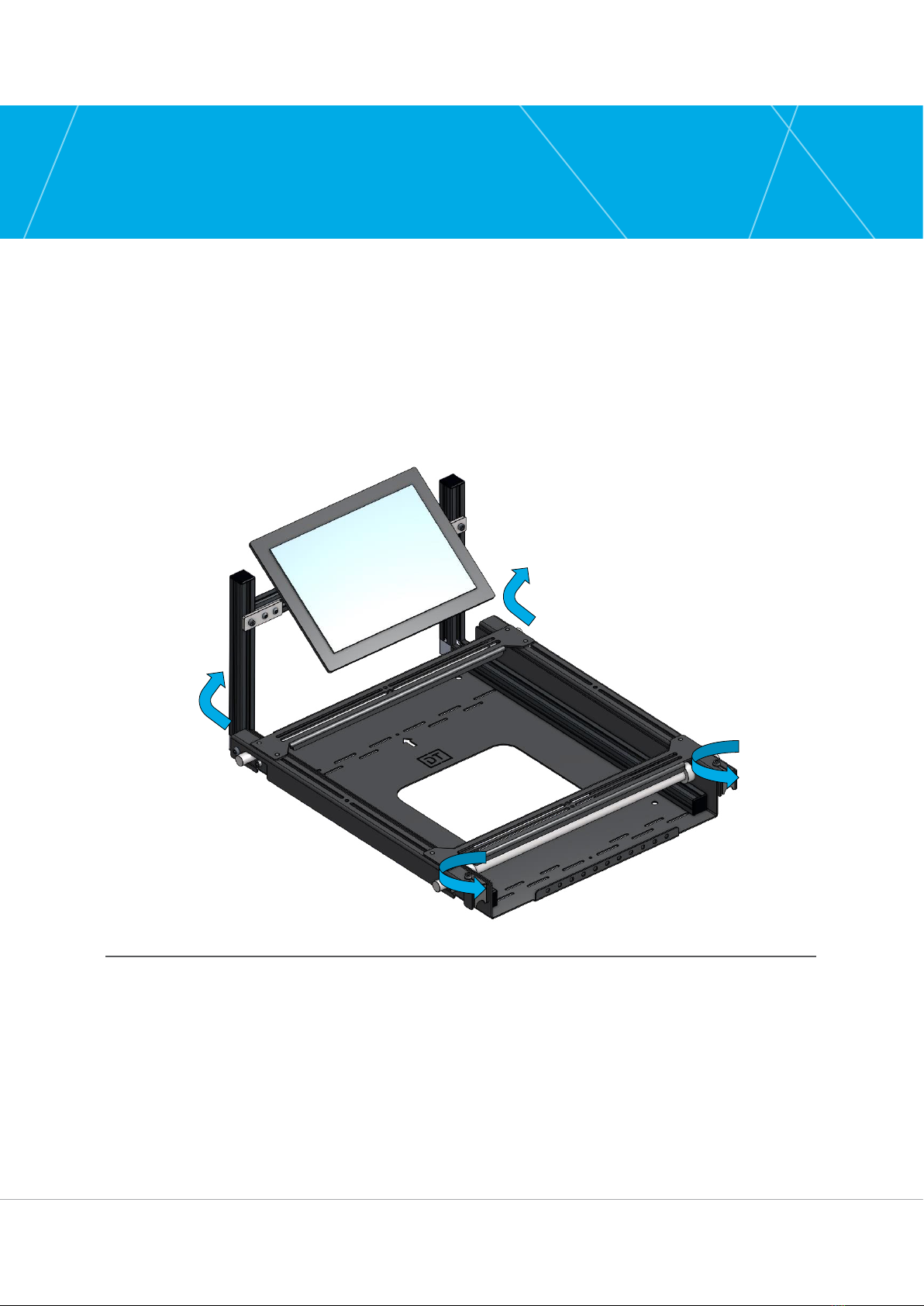
Unpack the mount ensuring that all the relevant parts are present.
1] Loosen the two lock plates and slide down to release.
2] Remove the projector frame from the mount plate.
Fig.1. Removing the projector mount plate
Vertical Mirror Mount [DT-VMMv2]
12
Manual Contents
Installation
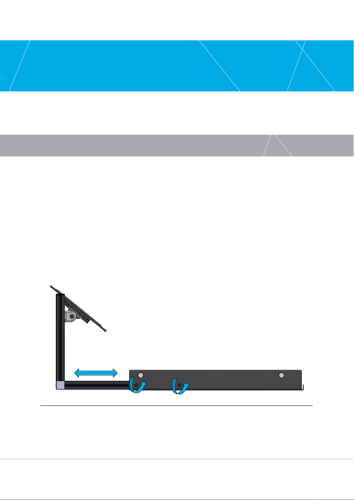
POSITIONING THE MIRROR
1] Slacken to two M6 Bolts on either side of the mount (Do not fully remove them).
2] The Mirror Mount will now be loose.
3] Pull out the Mirror Mount from the back plate.
4] Align in the desired position to suit the projector. (You may want to ‘Dry Fit’ the projector
to the mount first to gauge the correct position for the Mirror).
5] Re-tighten the M6 Bolts.
Fig.2. Pulling out the Mirror

13
Installation Manual – Revision 2.0
INSTALLING THE MOUNT PLATE
Fig. 3. Top and bottom mounting slots and bolt holes
Note that the orientation of the mount will depend if you want to have the mirror
mounted up or down. Installation is the same either way just rotate the mount plate
180 degrees.
1] Using the central top hole on the mount
plate screw the plate to the wall.
2] Rotate the mount plate to ensure that
it is vertical
3] Screw a second screw in the middle hole
of the rear row of mount holes
4] Using suitable fixings (to fix the total
weight of the projector and mount) fix
the mount plate to the wall using both
the top and bottom mounting slots or
larger 10mm bolt holes.
It is the installers responsibility to ensure that the wall/ceiling has the relevant
strength or additional support along with selected fixings to endure that the
combined weight of the projector and mount can be supported. It is recommended
that a total weight of 65kg with a safety factor of x5 is used in all calculations.
Vertical Mirror Mount [DT-VMMv2]
14
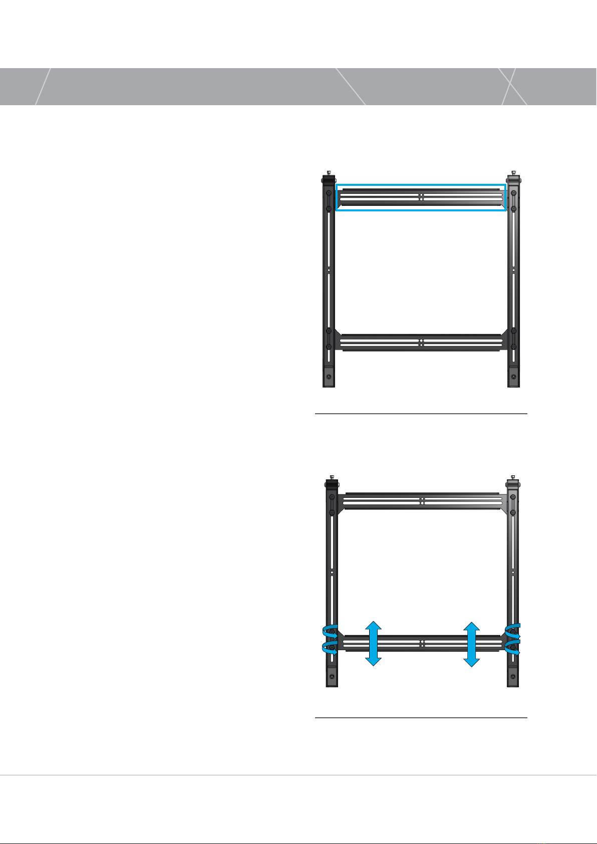
FITTING THE PROJECTOR FRAME
Fig.4. Fitting the projector frame to the projector
Fig.5. Fitting the bottom bar to the projector
1] Lay the projector with its base facing up
ready to fit the projector frame. Ensure
that the projector is laid on something
that protects it from scratches or
damage.
2] Lay the projector frame on the base
of the projector with the hooks of the
projector frame facing down towards the
back to the projector.
3] Use the relevant fixings and washers to
fit the top bar of the mount frame to the
projector.
4] Slacken the M6 nuts holding the bottom
bar of the mount frame and move this
until it aligns with the projectors rear set
of mounting holes. Use the 10mm socket
spanner provided for this.
5] Use the relevant fixings and washers to
fit the bottom bar of the mount frame to
the projector.
6] Tighten all the M6 nuts holding the
bottom bar and top bar of the mount
frame. Use the 10mm socket spanner
provided for this.

15
Installation Manual – Revision 2.0
HANGING THE PROJECTOR
Fig.6. Mount Plate with projector alignment
1] Lift the projector up to align it with the
mount plate on the wall
2] Lift the projector so that the hooks on
the projector plate engage with the rods
on the mount plate and pushed right
back.
3] Slide in the two lock plates and tighten
the lock bolts.
Ensure that the lock plates
are fully pushed up to the silver
hanging bar and are bolted tight
to prevent any movement.
Vertical Mirror Mount [DT-VMMv2]
16
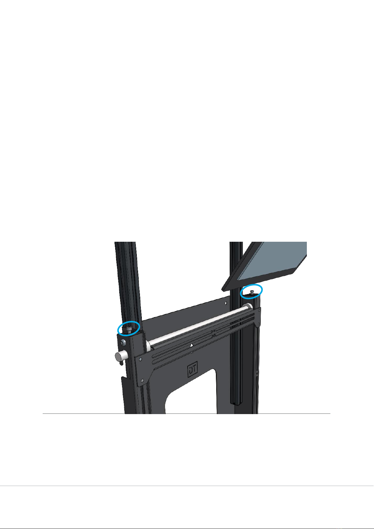
ROTATION ADJUSTMENT
If during installation the mount was not quite perpendicular to the screen it is possible to have
some rotation adjustment on the mount (+/- 5 degrees).
1] Slacken the two locking bolts on the locking plates at the bottom of the projector mount.
2] Using the adjuster knobs on the top of the mount rotate the adjuster screw pushing it against
the hanging bar. Do this until the desired rotation in achieved.
3] Tighten the locking bolts on the locking plates at the bottom of the mount ensuring that
the locking plate is tight against the handing bar.
Fig.7. Perpendicular rotation adjustment

17
Installation Manual – Revision 2.0
MIRROR ADJUSTMENT
Once installed and with the projector on use a Monoscope Test pattern on the projector to align
the mirror.
LENS CENTRING
1] Slacken the mirror bars bolt
2] Adjust to centre the mirror to the
centre of the lens. The exact location
will depend on the model of projector.
3] Tighten the mirror pivot bolt
PIVOT
1] Slacken the mirror pivot bolt
2] Adjust to align the picture
3] Tighten the mirror pivot bolt
When installing the mount and projector in a reverse orientation you will need to
pivot the mirror through 90 degrees from the standard shipping orientation.
Fig.8. Lens centring
Fig.9. Pivot adjustment
Vertical Mirror Mount [DT-VMMv2]
18
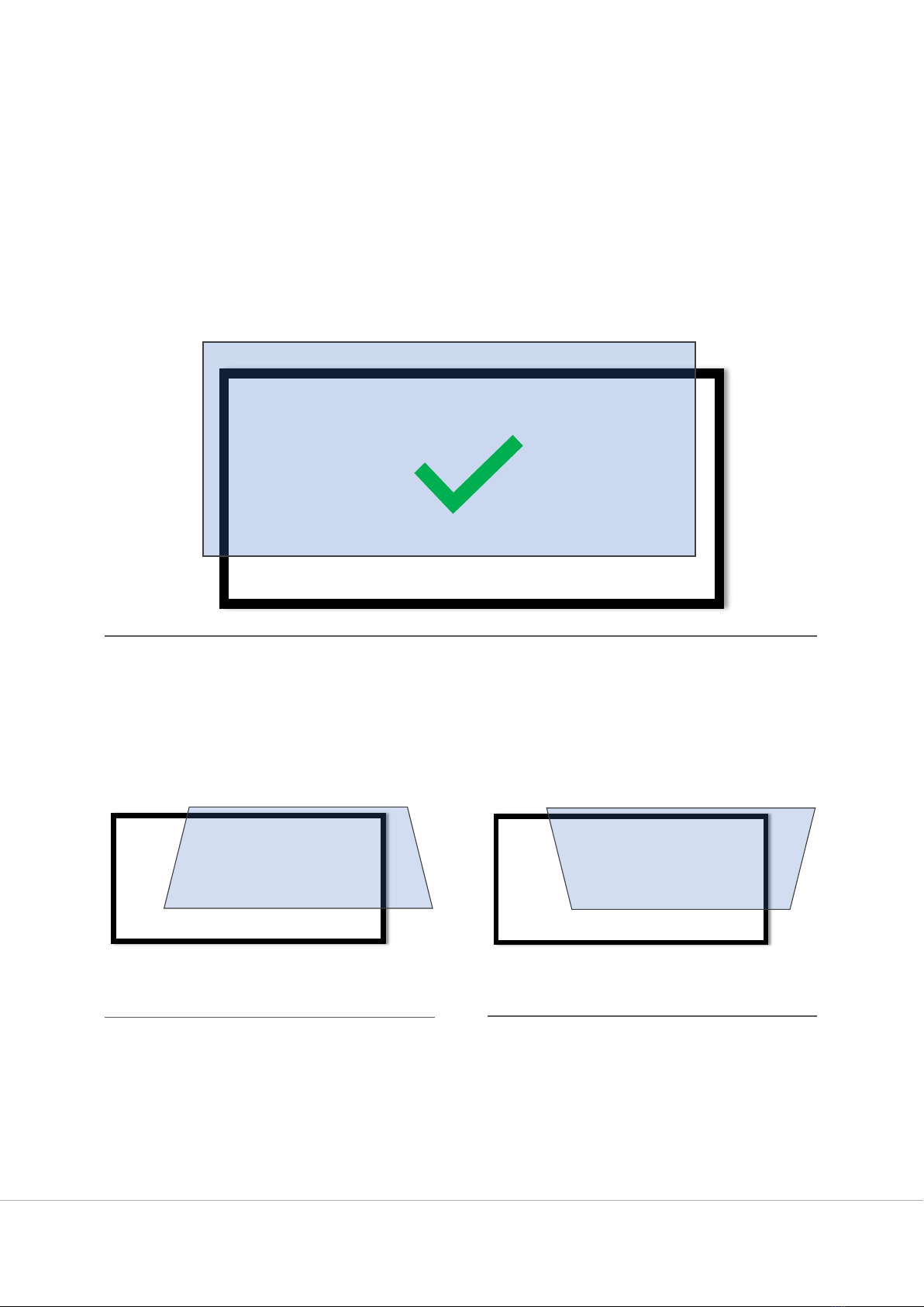
MIRROR PIVOT SETUP
If the projector being used has a ‘lens centre’ function first carry this out. If this is not available
centre the lens manually both vertically and horizontally.
Aim: You are trying to get a rectangular image roughly on the screen. You are not trying to use the
mirror to get the image exactly to fit the screen.
EXAMPLES:
Fig.11. Incorrect pivot setup - example 1
Fig.10. Correct pivot setup
Fig.12. Incorrect pivot setup - example 2
CORRECTIVE ACTIONS: Pivot Mirror backCORRECTIVE ACTIONS: Pivot Mirror forward

19
Installation Manual – Revision 2.0
Fig.13. Image alignment after the Mount setup
Projector Movements
Once you have a rectangular image the VMM is set up. Now use the projector lens shift and zoom
to align the image to the screen.

Table of contents
Other Display Indoor Furnishing manuals


