manuals.online logo
Brands
  1. Home
  2. •
  3. Brands
  4. •
  5. Displays2go
  6. •
  7. Lectern System
  8. •
  9. Displays2go OLILCTMMSBK User manual

Displays2go OLILCTMMSBK User manual

Contents
Ref. Qty. Description Ref. Qty. Description
A H1 57
H2
H3
H4
H5
57
12
16
4
Cam Lock
Cam Post
Dowel Pin
Caster Screw
Locking Caster
Step A Step B Step C
Join Panels
Insert Cam Tighten Cam
C
D
E
F
H
I
1 Top Panel
4 Long Vertical Panel
2
1
Bottom Panel
Side Shelf
2
2
2 Top Fence Panel
Connecting Panel
B1 1Left Side Panel
1
Bottom Fence Panel
H6
8Shelf Pin
ASSEMBLY INSTRUCTIONS
Podcart with Shelf
J
How to join 2 boards with CAM lock:
(a) Insert cam post into flat surface of a board.
Fit the hole in the edge of the joining board over
the cam post.
(b) Each cam lock has an open section at the
back. Insert the cam
lock into the cam. Be sure the opening fits the
head of the cam post.
(c) Use a screw driver to turn the cam lock
clockwise so it locks onto the head of the cam
post. Do not over tighten.
1 of 4
B2 1Right Side Panel
H7 4Hinge
Bottom Fence Panel
G2Shelf
1 Top Fence PanelK
42 Wood Screw
H8
C
Attention: Before you start assembling your podcart, please prepare a soft surface work area on the floor.
The only tool you will need is a screwdriver. Carefully remove all hardware from packaging and place the
hardware parts on the soft work area where they will not come in contact with the laminated wood lectern
components. To avoid damage to the laminated wood surfaces, keep hardware parts separated until they
are needed for assembly. 2 PERSON RECOMMENDED.
H
HI
I
H5
H4
2 Side Shelf Fence Panel1
12 Side Shelf Fence Panel
H2
Lock
2
H9
2H10
2H11
Left & Right Shelf Track
Left & Right Shelf Slide
1. Screw 18 cam posts[H2] into holes in Bottom Panel C and Bottom
Fence Panel H & I. Attach Bottom Fence Panel H to Bottom Panel C by
inserting cam posts into the cam lock holes. Then attach Bottom Fence
Panel I to the assembled C & H. Insert 14 cam locks[H1] into cam lock holes
in Panel C and Panel H, use a phillips screw driver to rotate cam locks
clockwise to secure cam posts.
2. Screw 4 Locking Casters[H5] into predrilled holes in Bottom
Panel C with 16 Caster Screws[H4].
2 DoorL
4H12 Grommet Cap & Sleeve
Washer
E
D
B1
B2
H1
H3
H3
H3
3. Screw 16 cam posts[H2] into holes in Panel D and E. Connect
Long Vertical Panels[D] with Connecting Panel[E] by inserting
Dowel Pins[H3] into predrilled holes in Connecting Panel[E].
4. Attach the assembled parts in Step 3 to Left Side Panel[B1] and
Right Side Panel[B2] by inserting cam posts into the cam lock holes .
Insert 16 cam locks[H1] into cam lock holes in Panel B1 and Panel
B2, use a phillips screw driver to rotate cam locks clockwise to
secure cam posts.
5. Attach the assembled parts in Step 4 to the assembled
parts in Step 2 by inserting cam posts & dowel pins into
the correct holes. Insert 4 cam locks[H1] into cam lock
holes in Panel B1 and Panel B2, use a phillips screw
driver to rotate cam locks clockwise to secure cam posts.
2 of 4
D
A
J
J
K
1
2
F
H11
H10 H6
H6
6. Screw 9 cam posts[H2] into holes in Top Fence Panel J & K. Attach
Top Fence Panel J to Top Panel A by inserting cam posts into the cam
lock holes. Then attach Top Fence Panel K to the assembled A & J. Insert
9 cam locks[H1] into cam lock holes in Panel J and Panel A, use a phillips
screw driver to rotate cam locks clockwise to secure cam posts.
7. Screw 2 cam posts[H2] into holes in Side Shelf Fence
Panel 1. Attach Side Shelf Fence Panel 1 to Side Shelf Fence
Panel 2 by inserting cam posts into the cam lock holes . Insert 2
cam locks[H1] into cam lock holes in Panel 2, use a phillips
screw driver to rotate cam locks clockwise to secure cam
posts.
8. Screw 12 cam posts[H2] into holes in Top Panel A underneath.
Attach the assembled parts in Step 7 to the assembled parts in Step 6
by inserting cam posts into the cam lock holes. Insert 6 cam locks[H1]
into cam lock holes in Panel 1 and 2, use a phillips screw driver to rotate
cam locks clockwise to secure cam posts.
9. Screw Left & Right Shelf Track[H10] to Panel 1 with 6
wood screws[H6]
10. Screw Left & Right Shelf Slide[H11] to Side Shelf F
with 4 wood screws[H6]
11. Insert Side Shelf F to Side Shelf Fence Panel 1 & 2
via Shelf Track & Slide.
3 of 4
H9
H7
H6
H6
H8
H3
H3
G
12. Attach the assembled parts in Step 11 to the assembled
parts in Step 5 by inserting cam posts & dowel pins into the
corrected holes. Insert 6 cam locks[H1] into cam lock holes in
Panel B1 & B2 & E, use a phillips screw driver to rotate cam locks
clockwise to secure cam posts.
13. Insert 8 Shelf Pins[H9] into the predrilled holes at two
levels(4 pins at one level) in Panel B1 & B2. Insert 2 Shelf
Panels[G] onto the Shelf Pins[H9] with slant method.
14. Attach 2 Doors[L] to Long Vertical Panels[D] with 4 Hinges[H7]
and 24 wood screws[H6]. Screw 2 Locks[H8] to Doors[L] with 8 wood
screws[H6].
L
15. Insert 4 Grommet Caps & Sleeves[H12] to predrilled
holes in Panel C & G & A.
4 of 4
H12

Other Displays2go Lectern System manuals

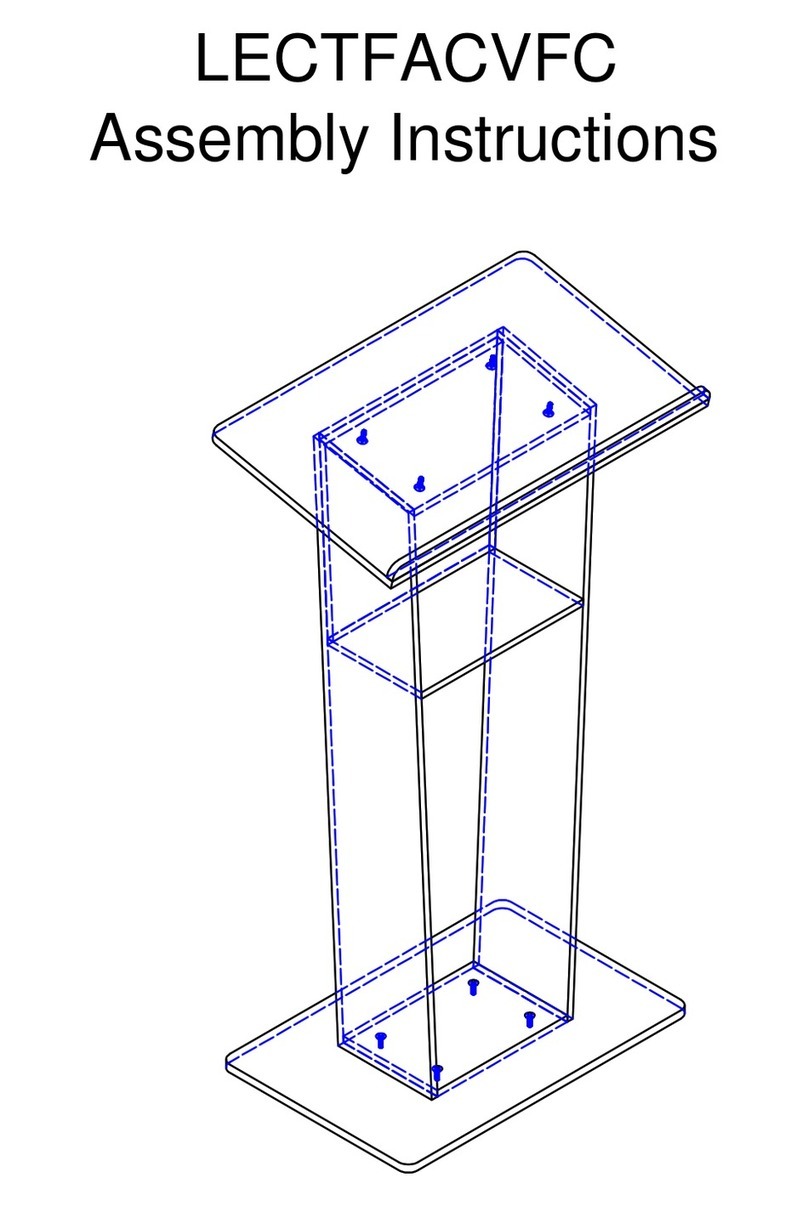
Displays2go LECTFACVFC User manual

Displays2go

Displays2go LECTFACVFC User manual

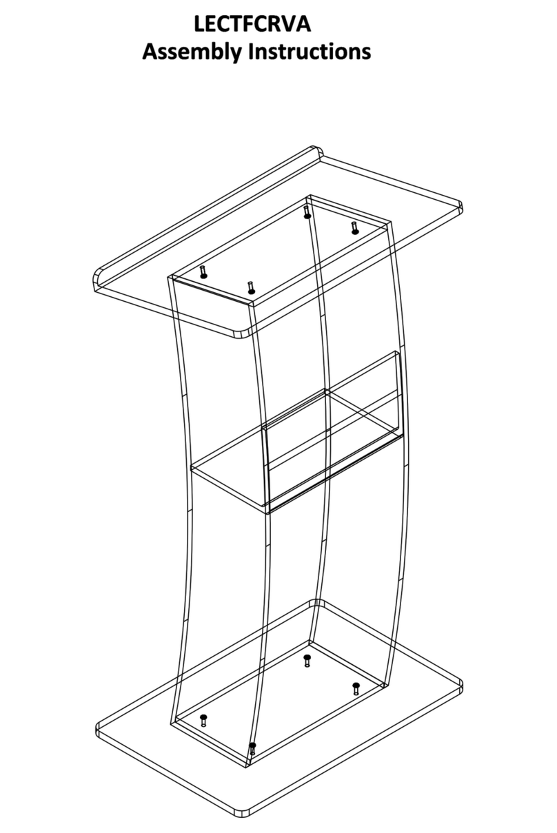
Displays2go LECTFCRVA User manual

Displays2go

Displays2go LECTFCRVA User manual

Popular Lectern System manuals by other brands

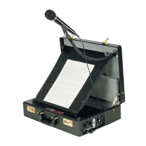
AmpliVox Patriot SS3040 Specifications

AmpliVox

AmpliVox Patriot SS3040 Specifications

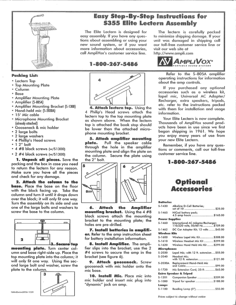
BST Pro AMC-70 instruction manual

BST Pro

BST Pro AMC-70 instruction manual

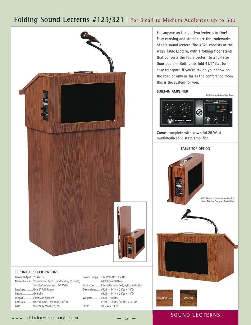
AmpliVox SS3230RTA Assembly instructions

AmpliVox

AmpliVox SS3230RTA Assembly instructions

J.Burrows MATRIX JBLECTURN Assembly instructions

J.Burrows

J.Burrows MATRIX JBLECTURN Assembly instructions

Anchor ACCLAIM ACC-6000U1 owner's manual

Anchor

Anchor ACCLAIM ACC-6000U1 owner's manual

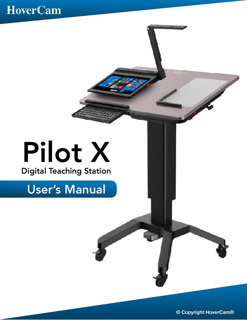
Oklahoma Sound A/V Cart Assembly manual

Oklahoma Sound

Oklahoma Sound A/V Cart Assembly manual

manuals.online logo
manuals.online logoBrands
  • About & Mission
  • Contact us
  • Privacy Policy
  • Terms and Conditions

Copyright 2025 Manuals.Online. All Rights Reserved.