manuals.online logo
Brands
  1. Home
  2. •
  3. Brands
  4. •
  5. DITEC
  6. •
  7. Remote Control
  8. •
  9. DITEC BIXLR4 Quick guide

DITEC BIXLR4 Quick guide

BIXLR4 433.92 MHz
BIXAR4 40.685 MHz
IP1618 07-05-2001
DITEC S.p.A.
Via Mons. Banfi, 3
21042 Caronno P.lla (VA) Italy
Tel.+39 02 963911 - Fax +39 02 9650314
www.ditec.it
Istruzione d’uso ricevitore quadricanale /
Four-channel use instruction
/ Manuel
d’utilisation recepteur quadricanaux
/ Bedienungshandbuch für Vierkanal-Empfänger
/
Manual para el uso del recepteur cuadricanal.
ISO 9001 - Cert. n° 0957/0
01
OUT1 OUT2 OUT3 OUT4
ANT
PWR SIG
PRG
L1 L2 L3 L4
T4
1 2 3 4
DIP
BIXMR
BIXLR4
BIXAR4
on
off
01
PWR SIG L1 L2 L3 L4
BIXMR
BIXLR4
BIXAR4
PRG
PRG
CH2
CH4
CH3
CH1
Attendere 10 s
Wait for 10 s
Nuovo TX
New TX
TX giàmemorizzato
Stored TX
1
2
3
70
130
26
I
GB
F
D
E
Alimentazione
Power supply
Alimentation
Stromzuführ
Alimentaciòn
Assorbimento
Absorption
Absorption
Stromaufnahme
Absorbimiento
N°codici mem
N°memo code
N°codes mém
N°Codes
N°codigos
Uscite N.O.
Outputs N.O.
Sortie N.O.
Aufgänge N.O.
Salidas N.O.
Temperatura
Temperature
Temperature
Temperatur
Temperatura
BIXLR4
12-24 V 25 mA (nom.)
85 mA max 1000 24 V / 1A -15°C/ +50°C
Grado di protez.
Degree of protect.
Degréde protec.
Schutzart
Grado de proteciòn
IP54
BIXAR4
2
DITEC S.P.A - IP1618 - BIXLR4-AR4
DICHIARAZIONE CE DI CONFORMITÀ
Fabbricante: DITEC S.p.A. - via Mons. Banfi, 3 - 21042 Caronno
Pertusella (VA) –ITALY.
Dichiara che i ricevitorI quadricanale BIXLR4 (433.92 MHz) e
BIXAR4 (40.685 MHz) sono conformi alle condizioni delle seguenti
direttive CE: Direttiva R&TTE 1999/5/CE, Direttiva EMC 89/336/
CEE e Direttiva bassa tensione 73/23/CEE.
Caronno Pertusella, 01-08-2000.
Fermo Bressanini
(Presidente)
1. Ricevitore
I radiocomandi serie BIX sono preposti per l’attivazione di automa-
tismi per vani passaggio e rispondono ai requisiti essenziali stabiliti
dalla direttiva 1999/5/CE R&TTE.
I ricevitori sono dotati del modulo memoria BIXMR e possono rice-
vere i codici di tutti i trasmettitori, ma attiveranno l’uscita di co-
mando solo se il codice ricevuto épresente nella lista dei codici
abilitati (max. 1000 codici).
Il ricevitore BIXLR4 èdotato di antenna (filo rigido L= 173 mm). In
alternativa èpossibile collegare l’antenna accordata BIXLA.
Il ricevitore BIXAR4 deve essere collegato all’antenna accordata BIXAA.
Per collegare l’antenna al RX usare cavo coassiale RG58 (max. 10 m).
L’antenna va posizionata il piùin alto possibile, lontano da strut-
ture metalliche (nel lampeggiante LAMP e LAMPH èprevisto un
morsetto per il collegamento dell’antenna).
Attenzione: per ottenere il grado di protezione IP54, l’unitàdi ge-
stione [1] deve essere fissata verticalmente (con la scritta DITEC
in basso a destra).
2. COLLEGAMENTI ELETTRICI
•Collegare i morsetti 0-1 ai morsetti 0-1 del Quadro Elettrico.
•Collegare i morsetti OUT1, OUT2, OUT3, OUT4 in base alle
proprie esigenze.
3. ABILITAZIONE TRASMETTITORI.
3.1 Dare alimentazione, il led verde PWR si accende.
3.2 Premere il pulsante PRG sul ricevitore, il led giallo SIG si accende,
oppure premere PRG di un trasmettitore giàmemorizzato (entro
la portata del ricevitore alimentato).
3.3 Effettuare una trasmissione premendo uno qualsiasi dei pul-
santi CH del nuovo trasmettitore. Durante questa fase il led
giallo SIG lampeggia. Il trasmettitore viene cosìabilitato.
I codici vengono memorizzati sul modulo memoria BIXMR
(fino ad un max. di 1000 codici).
Se all’accensione non viene rilevata la presenza del modulo
memoria BIXMR, il ricevitore vàin allarme causando un
lampeggio veloce del led giallo SIG.
Attenzione: l’inserimento e l’estrazione del BIXMR de-
vono essere effettuati senza alimentazione.
Se la memoria BIXMR ègiàcompleta dei 1000 codici, il led
giallo SIG lampeggia velocemente per 5 s e il ricevitore ritor-
na al normale funzionamento.
3.4 La memoria BIXMR non accetta ripetizioni del medesimo codi-
ce (se il codice letto ègiàstato memorizzato il led SIG lampeg-
gia velocemente). Alla fine di ogni memorizzazione il ricevitore
rimane in attesa per 10 s, se entro questo intervallo non viene
letto un ulteriore codice la fase di apprendimento termina.
N.B.: Mediante l’unitàdi gestione PPC 1 èpossibile aggiungere, can-
cellare, copiare su un altro modulo memoria o proteggere mediante
Password, i codici della memoria BIXMR.
4. SELEZIONE CANALI
Premendo CH1 (del trasmettitore) si attiva OUT1 (accensione led L1).
Lo stesso comportamento avviene per gli altri canali (CH2, CH3 e CH4).
La funzionalitàdelle uscite OUT1, 2, 3 e 4 èimpostabile dal relativo
Dip-Switch (DIP1→OUT1, ecc):
DIP1, 2, 3, 4 in OFF = modalitàimpulsiva;
DIP1, 2, 3 in ON = modalitàpasso/passo;
DIP4 in ON = modalitàtemporizzata.
Il trimmer T4 regola il tempo di attivazione di OUT4 (da 10 a 165 s)
quando il DIP4 èin ON.
5. Cancellazione totale dei codici.
Per svuotare completamente il modulo memoria BIXMR premere il
tasto PRG per 3 s (il led giallo SIG lampeggia); entro 5 s ripremere
il tasto PRG per confermare la cancellazione (il led giallo SIG lam-
peggia velocemente).
ITALIANO
Tutti i diritti sono riservati
I dati riportati sono stati redatti e controllati con la massima cura.
Tuttavia non possiamo assumerci alcuna responsabilitàper even-
tuali errori, omissioni o approssimazioni dovute ad esigenze tecni-
che o grafiche.
All right reserved
All data and specifications have been drawn up and checked with
the greatest care. The manufacturer cannot however take any
responsibility for eventual errors, ommisions or incomplete data
due to technical or illustrative purposes.
Touts droits reservés
Les informations mentionnées dans ce catalogue ont étécontrolées
avec la plus grande attention. Toutefois, nous déclinos toute
responsabilitéen cas d’erreurs, omissions ou approximations
dépendant d’exigences techniques ou graphiques.
Alle Rechte vorbehalten
Die wiedergegebenen Daten wurden mit höchster Sorgfalt
zusammengestellt und überprüft. Es kann jedoch keinerlei
Verantwortung für eventuelle Fehler, Auslassungen oder
Näherungen, die technischen oder graphischen Notwendigkeiten
zuzuschreiben sind, übernommen werden.
Todos los derechos son reservados
Los datos que se indican han sido redactados y controlados con la
màxima atenciòn. Sin embargo no podemos asumir ninguna
responsabilidad por eventuales errores, omisiones o
aproximaciones debidas a exigencias técnicas o gràficas.
PAESI CHE HANNO RECEPITO LA DIRETTIVA
R&TTE 1999/5/CE
COUNTRIES WHICH HAVE ADMITTED THE R&TTE
DIRECTIVE, 1999/5/C, INTO THEIR LEGISLATION.
COUNTRY
AUSTRIA
BELGIUM
DENMARK
ESTONIA
FINLAND
FRANCE
GERMANY
GREECE
HUNGARY
ICELAND
IRELAND
ITALY
LICHTENSTEIN
LUXEMBOURG
NETHERLANDS
NORWAY
PORTUGAL
SPAIN
SWEDEN
SWITZERLAND
UNITED KINGDOM
STATUS
NO LICENCE REQUIRED
NO LICENCE REQUIRED
NO LICENCE REQUIRED
NO LICENCE REQUIRED
NO LICENCE REQUIRED
NO LICENCE REQUIRED
NO LICENCE REQUIRED
NO LICENCE REQUIRED
NO LICENCE REQUIRED
NO LICENCE REQUIRED
NO LICENCE REQUIRED
NO LICENCE REQUIRED
NO LICENCE REQUIRED
NO LICENCE REQUIRED
NO LICENCE REQUIRED
NO LICENCE REQUIRED
NO LICENCE REQUIRED
NO LICENCE REQUIRED
NO LICENCE REQUIRED
NO LICENCE REQUIRED
NO LICENCE REQUIRED
3DITEC S.P.A - IP1618 - BIXLR4-AR4
EC DECLARATION OF CONFORMITY
Manufacturer: DITEC S.p.A. - via Mons. Banfi, 3 - 21042 Caronno
Pertusella (VA) –ITALY.
Herewith declares that the four-channel receivers BIXLR4 (433.92
MHz) and BIXAR4 (40.685 MHz) are in conformity with the provi-
sions of the following EC directives: R&TTE Directive 1999/5/EC,
EMC Directive 89/336/EEC and Low Voltage Directive 73/23/EEC.
Caronno Pertusella, 01-08-2000.
Fermo Bressanini
(Chairman)
1. Receiver
The BIX series of remote controls are designed for the activation of
automatic accesses and are built in compliance with the R&TTE
Directive, 1999/5/C.
The receivers are equipped with a BIXMR storage module and can
receive the codes of all transmitters, but will only respond upon
receiving a code which is included in them file of authorised codes
(max. 1000 codes).
The receiver BIXLR4 is equipped with a 173 mm long rigid anten-
na. Alternatively, it may be linked up to a BIXLA.
The BIXAR4 receiver must be linked up to the BIXAA tuned an-
tenna. Tuned antenna by means of an RG58 coaxial cable with a
maximum length of 10 metres.
The antenna must be mounted as high up as possible, away from
any metal structures (the LAMP and LAMPH flashing lights are
provided with a clamp for linking up of the antenna).
Attention: For IP54 class protection, the management unit [1] must
be installed vertically (i.e., with the DITEC name on the bottom
right-hand side).
2. ELECTRICAL CONNECTION
•Connect terminals 0-1 to terminals 0-1 of the electric board.
•Connect terminals OUT1, OUT2, OUT3, OUT4 as required.
3. ENABLING THE TRANSMITTERS
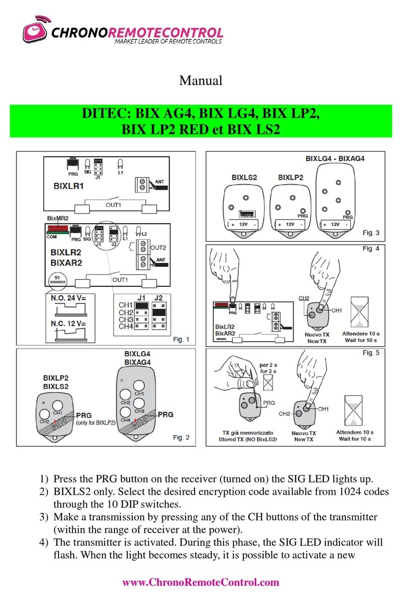
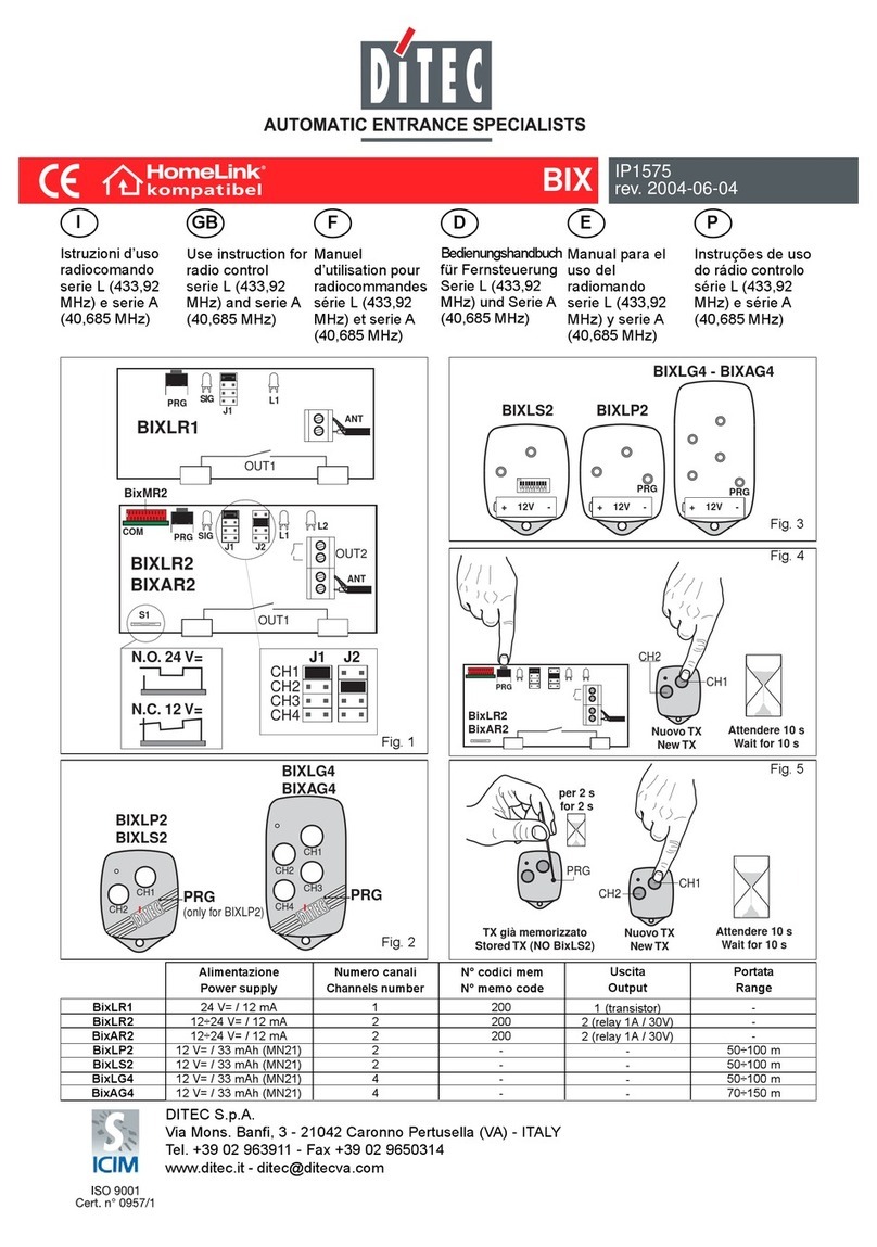
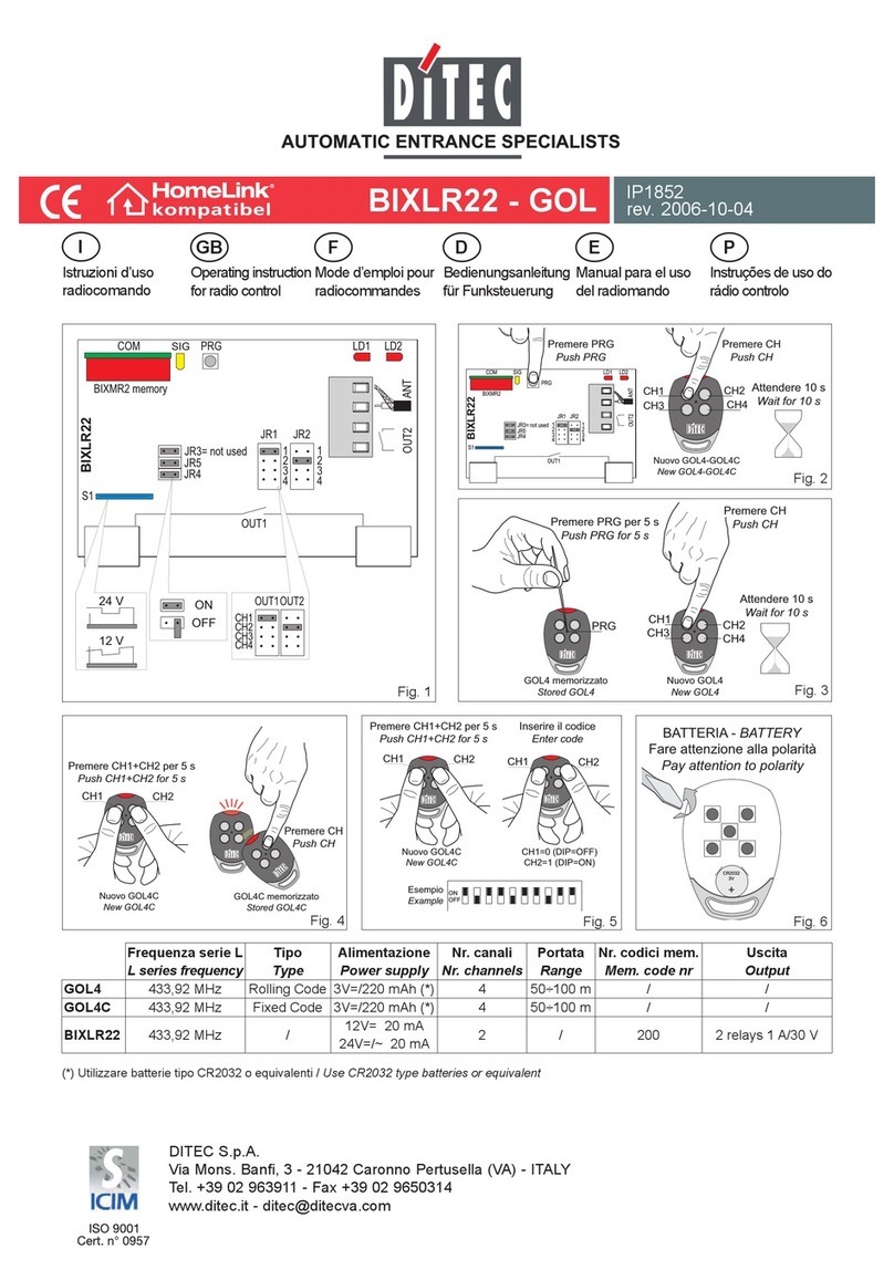
3.1 Power on. The green PWR LED will light up.
3.2 Press button PRG on the receiver, the yellow SIG LED will
light up, or press PRG of a previously stored transmitter
(within the range of the powered receiver).
3.3 Carry out a transmission by pressing any of the CH buttons
of the new transmitter. During this operation the yellow SIG
LED will be flashing. The transmitter is enabled.
Codes are stored in the BIXMR storage module (up to a
maximum of 1000 codes).
In case of the BIXMR storage module not being detected
upon the unit being turned on, the receiver enters into an
alarm status and the yellow SIG LED starts flashing quickly.
Attention: Insertion and removal of the BIXMR module
must be made with the unit powered off.
In case of the BIXMR memory being full (1000 codes stored),
the yellow SIG LED flashes quickly for 5 seconds after which
the receiver returns to normal operation.
3.4 The BIXMR memory will not accept repetition of the same
code (if the code which has been read has already been
stored, the SIG LED flashes quickly). Upon each new code
being logged in, the receiver remains in a stand-by status for
10 seconds. If no new code is entered within this interval the
unit exits from the learning mode.
Note: Using the PPC 1 management unit it is possible to
add, delete, copy on another storage module, or protect by
Password, the BIXMR memory codes.
4. SELECTING THE CHANNELS
Pressing of CH1 on the transmitter activates OUT1 (LED L1 comes
on). The procedure is the same for all the other channels (CH2,
CH3 and CH4).
OUT1, 2, 3 and 4 operating mode can be selected by setting the
corresponding Dip-Switch (DIP1→OUT1, etc.) accordingly:
DIP1, 2, 3, 4 to OFF = impulse mode
DIP1, 2, 3 to ON = step-by-step mode
DIP4 to ON = time delay mode.
Activation time of OUT4 (10 to 165 seconds) can be adjusted via
trimmer T4 when DIP4 is set to ON.
5. Deletion of all codes
To delete all codes from the BIXMR storage module, press PRG
and keep it pressed for 3 seconds the yellow SIG LED flashes),
after which press again within 5 seconds to confirm deletion (the
yellow SIG LED flashes quickly).
DECLARATION CE DE CONFORMITE
Fabricant: DITEC S.p.A. - via Mons. Banfi, 3 - 21042 Caronno
Pertusella (VA) –ITALY.
Déclare ci-après que les recepteurs quadricanaux BIXLR4 (433.92
MHz) et BIXAR4 (40.685 MHz) sont conforme aux dispositions des
directives CEE suivantes: Directive R&TTE 1999/5/CE, Directive
EMC 89/336/CEE et Directive basse tension 73/23/CEE.
Caronno Pertusella, 01-08-2000.
Fermo Bressanini
(Président)
1. Récepteurs
Les télécommandes radio de la série BIX permettent d’activer des
automatismes pour les ouvertures de passage et répondent aux
exigences essentielles de la directive 1999/5/CE R&TTE.
Les récepteur sont équipédu module mémoire BIXMR et peut
recevoir les codes de tous les émetteurs, mais eux activera la sortie
de commande que si le code reçu est présent dans la liste des
codes autorisés (max. 1000 codes).
Le récepteur BIXLR4 est dotéd’une antenne (fil rigide L= 173 mm).
En alternative, il est possible de relier l’antenne accordée BIXLA.
Le récepteur BIXAR4 doit être reliéàl’antenne accordée BIXAA.
Pour relier l’antenne au récepteur, utiliser un câble coaxial RG58
(max. 10 m).
L’antenne doit être installée le plus haut possible, loin de structures
métalliques (les clignotants LAMP et LAMPH sont dotés d’une borne
pour le branchement de l’antenne). Attention: pour obtenir le de-
gréde protection IP54, l’unitéde gestion [1] doit être fixée vertica-
lement (la marque DITEC doit se trouver en bas àdroite).
2. RACCORDEMENTS ELECTRIQUES
•Relier les bornes 0-1 aux bornes 0-1 de l’armoire électrique.
•Relier les bornes OUT1, OUT2, OUT3, OUT4 en fonction des
exigences spécifiques.
3. ACTIVATION EMETTEURS
3.1 Mettre sous tension: la led verte PWR s’allume.
3.2 Enfoncer le bouton PRG sur le récepteur, la led jaune SIG
s’allume, ou bien appuyer sur la touche PRG d’un émetteur
déjàen mémoire (dans les limites de portée du récepteur
alimenté).
3.3 Effectuer une transmission en appuyant sur l’un quelconque
des boutons CH du nouvel émetteur. Pendant cette phase
la led jaune SIG clignote. L’émetteur est activé.
Les codes sont stockés dans le module mémoire BIXMR (jusqu’à
un maximum de 1000 codes).
Si, àla mise en marche, la présence du module mémoire BIXMR
n’est pas détectée, le récepteur se met en état d’alarme, faisant
clignoter rapidement la led jaune SIG.
Attention: l’enfichage et l’extraction du module mémoire
BIXMR doivent s’effectuer sans alimentation.
Si la mémoire BIXMR comprend déjà1000 codes, la led
jaune SIG clignote rapidement pendant 5 secondes et le ré-
cepteur revient au fonctionnement normal.
3.4 La mémoire BIXMR n’accepte pas de répétitions d’un même
code (si le code lu a déjàétéenregistré, la led SIG clignote
rapidement). A la fin de chaque mémorisation, le récepteur
reste en attente pendant 10 secondes et, si un autre code
n’est pas lu dans ce laps de temps, la phase d’apprentis-
sage se termine.
N.B.: Au moyen de l’unitéde gestion PPC 1, les codes de la
mémoire BIXMR peuvent être ajoutés, supprimés, copiéns
dans un autre module de mémoire ou protégéavec Password.
4. SELECTION CANAUX
En appuyant sur CH1 (de l’émetteur) on active OUT1 (la led L1 s’al-
lume). Le comportement est le même pour les autres canaux (CH2,
CH3 et CH4).
La fonction des sorties OUT1, 2, 3 et 4 se sélectionne au moyen du
commutateur DIP correspondant (DIP1→OUT1, etc.):
DIP1, 2, 3, 4 sur OFF = mode impulsionnel;
DIP1, 2, 3 sur ON = mode pas àpas;
DIP4 sur ON = mode temporisé.
Le trimmer T4 règle le temps d’activation de OUT4 (10 à165 s)
quand DIP4 est sur ON.
5. Suppression totale des codes.
Pour vider complètement le module mémoire BIXMR appuyer sur
la touche PRG pendant 3 s (la led jaune SIG clignote); dans les 5
s appuyer de nouveau sur la touche PRG pour valider la suppression
(la led jaune SIG clignote rapidement).
ENGLISH
FRANÇAIS

4
DITEC S.P.A - IP1618 - BIXLR4-AR4
DECLARACIÓN CE DE CONFORMIDAD
Fabricante: DITEC S.p.A. - via Mons. Banfi, 3 - 21042 Caronno
Pertusella (VA) –ITALY.
Declara que los recepteurs cuadricanal BIXLR4 (433.92 MHz) y
BIXAR4 (40.685 MHz) son conformes con las condiciones de las
siguientes directivas CE: Directiva R&TTE 1999/5/CE, Directiva
EMC 89/336/CEE y Directiva baja tensión 73/23/CEE.
Caronno Pertusella, 01.08.2000.
Fermo Bressanini
(Presidente)
1. Receptor
Los radiomandos de serie BIX se utilizan para la activación de aparatos
automatizados previstos para áreas de paso y están conformes con los
requisitos básicos establecidos por la directiva 1999/5/CE R&TTE.
Les receptores están dotado del módulo de memoria BIXMR y
pueden recibir los códigos de todos los transmisores, pero activará
la salida de mando solamente si el código recibido estápresente
en la lista de los códigos habilitados (máx. 1000 códigos).
El receptor BIXLR4 posee una antena (alambre rigido L= 173 mm).
Como alternativa es posible conectar la antena facilitada BIXLA.
El receptore BIXAR4 debe ser conectado a la antena sintonizada
BIXAA. Para conectar la antena al receptor usar un cable coaxial
RG58 (máx.10 m).
La antena ha de ser colocada lo más alto posible, lejos de
estructuras metálicas ( en el indicador LAMP y LAMPH tenemos
un borne para la conexión de la antena ).
Attenzione: para obtener el grado de protección IP54, la unidad
de gestión [1] debe ser fijada verticalmente (con la escritura DITEC
abajo a la derecha).
2. CONEXIONES ELECTRICAS
•Conectar los bornes 0-1 a los bornes 0-1 del tablero eléctrico.
•Conectar los bornes OUT1, OUT2, OUT3, OUT4 en base a las
exigencias específicas.
3. HABILITACION DE LOS TRANSMISORES
3.1 Poner bajo tensión, el led verde PWR se enciende.
3.2 Pulsar el botòn PRG en el receptor, el led amarillo SIG se
enciende, o bien presionar PRG de un transmisor ya
memorizado (dentro de los lìmites de capacidad del
receptor alimentado).
3.3 Efectuar una transmisiòn presionando un pulsador cualquiera
CH del nuevo transmisor. Durante esta fase el led amarillo
SIG relampaguea. De esta manera se habilita el transmisor.
Los códigos son memorizados en el módulo de memoria
BIXMR (hasta un máx. de 1000 códigos).
Si al encender no se detecta la presencia del módulo de me-
moria BIXMR, el receptor entra en alarma, causando un
relampagueo veloz del led amarillo SIG.
Atención: la inserción y extracción del módulo memoria
BIXMR deben ser efectuadas sin alimentación.
Si la memoria BIXMR ya posee los 1000 códigos, el led
amarillo SIG relampaguea velozmente durante 5 seg. y el
receptor regresa al funcionamiento normal.
3.4 La memoria BIXMR no acepta repeticiones del mismo código
(si el código leído ya se ha memorizado el led SIG relampaguea
rápidamente). Al final de cada memorización el receptor
permanece en espera durante 10 seg., si dentro de este
intervalo de tiempo no es leído un código ulterior, la fase de
aprendizaje termina.
N.B.: Mediante la unidad de gestiòn PPC 1 se puede agregar,
cancelar, copiar sobre otro mòdulo se memoria, o proteger a
través de Password, los codigos de la memoria BIXMR.
4. SELECCION DE LOS CANALES
Presionando CH1 (del transmisor) se activa OUT1 (encendido del
led L1). Lo mismo ocurre para los otros canales (CH2, CH3 y CH4).
La funcionalidad de las salidas OUT1, 2, 3 y 4 son programables
desde el Dip-Switch (DIP1→OUT1, etc):
DIP1, 2, 3, 4 en OFF = modalidad impulsiva;
DIP1, 2, 3 en ON = modalidad paso/paso;
DIP4 en ON = modalidad temporizada.
El trimmer T4 regula el tiempo de activación de OUT4 (de 10 a 165
seg.) cuando el DIP4 estáen ON.
5. Cancelación total de los códigos.
Para vaciar completamente la memoria BIXMR, presionar la tecla
PRG durante 3 seg (el led amarillo SIG relampaguea); dentro de 5
seg. volver a presionar la tecla PRG para confirmar la cancelación
(el led amarillo SIG relampaguea rápidamente).
ESPAÑOL
EG-KONFORMITÄTSERKLÄRUNG
Hersteller: DITEC S.p.A. - via Mons. Banfi, 3 - 21042 Caronno Per-
tusella (VA) –ITALY.
erklärt hiermit, daßdie Vierkanal-Empfänger BIXLR4 (433.92 MHz)
und BIXAR4 (40.985 MHz) mit den einschlägigen Bestimmungen
folgender EG-Rchtlinien übereinstimmen: R&TTE-Richtlinie 1999/
5/EWG, EMC-Richtlinie 89/336/EWG und Niederspannungsrichtlinie
73/23/EWG.
Caronno Pertusella, 01-08-2000.
Fermo Bressanini
(Präsident)
1. Empfänger
Die Fernsteuerungen der Typenreihe BIX dienen der Aktivierung
von Tür- und Torantrieben und entsprechen den wesentlichen
Anforderungen der Richtlinie 1999/5/CE R&TTE.
Die Empfänger sind mit einem Speichermodul BIXMR ausgestat-
tet und kann die Codes aller Sender empfangen. Sie aktivieren den
Steuerausgang jedoch nur, wenn der empfangene Code in der Li-
ste der aktivierten Codes enthalten ist (max. 1000 Codes).
Der Empfänger BIXLR4 ist mit einer Antenne ausgestattet (L=173
mm). Alternativ kann die Antenne BIXLA angeschlossen werden.
Der Empfänger BIXAR4 mußt mit der abgestimmten Antenne
BIXAA verbunden werden. Zum Anschlußder Antenne ein Koaxi-
alkabel RG58 (max. 10 m) verwenden.
Die Antenne mußmöglichst weit oben positioniert und weg von
Metallstrukturen positioniert werden (in der Warnleuchte LAMP und
LAMPH ist eine Klemme für den Antennenanschlußvorgesehen.)
Achtung: Um den Schutzgrad IP54 zu erhalten, mußdas Befehls-
gerät [1] vertikal angebracht werden (Aufschrift DITEC unten rechts).
2. ELEKTRISCHE ANSCHLÜSSE
•Klemmen 0-1 an die Klemmen 0-1 der Steuerung anschließen.
•Klemmen OUT1, OUT2, OUT3, OUT4 nach den eigenen An-
forderungen anschließen.
3. AKTIVIERUNG DER SENDUNG
3.1 Strom zuführen. Die grüne Lampe PWR leuchtet auf.
3.2 Taste PRG am Empfänger drücken. Die gelbe Lampe SIG
leuchtet auf. Oder PRG eines bereits gespeicherten Sensor
drücken (innerhalb der Reichweite des mit Strom versorg-
ten Empfängers).
3.3 Eine Übertragung durchführen, indem eine der CH-Tasten des
neuen Senders gedrückt wird. Während dieser Phase blinkt die
gelbe Lampe SIG. So wird der Sender aktiviert.
Die Codes werden auf dem Speichermodul BIXMR gespeichert
(max. 1000 Codes).
Wenn beim Einschalten festgestellt wird, daßkein Speichermodul
BIXMR vorhanden ist, geht der Empfänger in Alarmzustand und
die gelbe Lampe SIG blinkt schnell. Achtung: Beim Einsetzen
und Herausnehmen des Speichermoduls BIXMR darf kein
Strom zugeführt werden.
Wenn 1000 Codes im Speichermodul BIXMR gespeichert
sind, blinkt die gelbe Lampe SIG 5 Sekunden lang schnell,
und der Empfänger kehrt zur normalen Betriebsart zurück.
3.4 Der Speicher BIXMR akzeptiert keine Wiederholung des glei-
chen Codes (wenn der gelesene Code bereits gespeichert
wurde, blinkt die Lampe SIG schnell). Am Ende einer Spei-
cherung bleibt der Empfänger 10 Sekunden in Wartestellung.
Wenn innerhalb dieses Intervalls kein weiterer Code gelesen
wird, ist die Lernphase beendet. N.B.: Mit der Steuereinheit
PPC1 können die Codes des BIXMR-Speichers hinzugefügt,
gelöscht und auf ein anderes Speichermedium kopiert oder
mit Hilfe eines Passworts geschützt werden.
4. AUSWAHL DER KANÄLE
Durch Drücken von CH1 (am Sender) wird OUT1 aktiviert (LED L1
leuchtet auf). Das gleiche geschieht bei den anderen Kanälen (CH2,
CH3 und CH4).
Die Funktionsweise der Ausgänge OUT1, 2, 3 und 4 kann über den
entsprechenden DIP-Schalter (DIP1→OUT1 usw.) eingestellt werden.
DIP1, 2, 3, 4 in OFF-Stellung = Impulsbetrieb
DIP1, 2, 3 in ON-Stellung = Schrittbetrieb
DIP 4 in ON-Stellung = zeitgesteuerter Betrieb
Der Trimmer T4 regelt die Aktivierungszeit von OUT4 (von 10 bis
165 Sekunden), wenn DIP4 in ON-Stellung ist.
5. Löschung aller Codes
Um das Speichermodul BIXMR komplett zu löschen, wird die Taste
PRG 3 Sekunden lang gedrückt (die gelbe Lampe SIG blinkt). Inner-
halb von 5 Sekunden mußerneut die Taste PRG gedrückt werden, um
die Löschung zu bestätigen (die gelbe Lampe SIG blinkt langsam).
DEUTSCH

This manual suits for next models

1

Other DITEC Remote Control manuals

DITEC GOL4 User manual

DITEC

DITEC GOL4 User manual

DITEC GOL4-C Owner's manual

DITEC

DITEC GOL4-C Owner's manual

DITEC Gol4C Owner's manual

DITEC

DITEC Gol4C Owner's manual

DITEC BIXLR22-GOL User manual

DITEC

DITEC BIXLR22-GOL User manual

DITEC BIXLR22-GOL User manual

DITEC

DITEC BIXLR22-GOL User manual

DITEC BIX L Series Operating and maintenance manual

DITEC

DITEC BIX L Series Operating and maintenance manual

DITEC BIX L Series Operating and maintenance manual

DITEC

DITEC BIX L Series Operating and maintenance manual

DITEC Bixa G4 Owner's manual

DITEC

DITEC Bixa G4 Owner's manual

DITEC BIX AG4 User manual

DITEC

DITEC BIX AG4 User manual

Popular Remote Control manuals by other brands

Grundig G-VRC-01 user manual

Grundig

Grundig G-VRC-01 user manual

Astro-Smart Meade RCDA user manual

Astro-Smart

Astro-Smart Meade RCDA user manual

GameChanger ESPN user manual

GameChanger

GameChanger ESPN user manual

Classic IRC87286-OD User instructions

Classic

Classic IRC87286-OD User instructions

X10 KR15A Installation and operating instructions

X10

X10 KR15A Installation and operating instructions

Sea gull lighting 16005-15 manual

Sea gull lighting

Sea gull lighting 16005-15 manual

YOODA MELODY Series quick start guide

YOODA

YOODA MELODY Series quick start guide

Tele Radio PN-RX-MN5 installation instructions

Tele Radio

Tele Radio PN-RX-MN5 installation instructions

taranis F3J Setup guide

taranis

taranis F3J Setup guide

Home Theater Master MRF-250 installation manual

Home Theater Master

Home Theater Master MRF-250 installation manual

Olympus RM-1 instructions

Olympus

Olympus RM-1 instructions

Hisense J1-91 instructions

Hisense

Hisense J1-91 instructions

INVENTOR P9MVI32-12WiFi user manual

INVENTOR

INVENTOR P9MVI32-12WiFi user manual

Avermedia AVerVision CP300 Quick reference guide

Avermedia

Avermedia AVerVision CP300 Quick reference guide

Dormakaba RCI 910TC-WRB Installation

Dormakaba

Dormakaba RCI 910TC-WRB Installation

Hearth and Home Technologies SMART-STAT Installation and operating instructions

Hearth and Home Technologies

Hearth and Home Technologies SMART-STAT Installation and operating instructions

Trace Engineering RC7 manual

Trace Engineering

Trace Engineering RC7 manual

Alber e-motion operating instructions

Alber

Alber e-motion operating instructions

manuals.online logo
manuals.online logoBrands
  • About & Mission
  • Contact us
  • Privacy Policy
  • Terms and Conditions

Copyright 2025 Manuals.Online. All Rights Reserved.