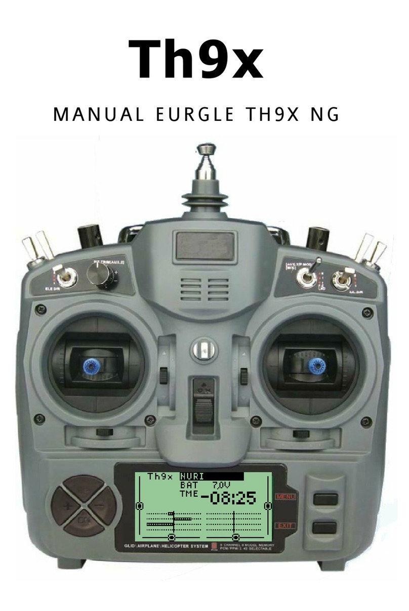
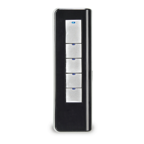
Eurgle rcps61207 User manual

Eurgle 2.4Ghz 9 Channel Digital
Programmable LCD Radio Gear
rcps61207

EURGLE:::
Table
of
contents
.1..lllkodJH:Jion. . .
..
2
z:.
5e
rvl
ce
. . . . 2 9. 14 Ai
IDiff
. ·
..
..
35
9.
15
AIR
BRAKES
. .
....
:35
3:--Meaiil
ng
C!1
specia
l markliigs
....
3
~
.._
TrAnsmltter_
con
tr
ol
....
5 9. 16
EL
E. F
lap
..
.
...
36
9
.17
V_
Tail
......
36
5 .
ID
S
I8
1
....
7
9.
18
ELEVON
..
.. ..
37
5. I
Receiver
and
servo
connect
ion.s
..
.
..
7
9.
19
Snap
-
roll
..
.. ..
37
5. 2
Charging
the
Ni-
Cd
b
atteries
......
8
5. 3 Range
Testi
ng Your R/ C
System
8
C::
6
.:
M
il
lt
t:L
CD
.
a
nd
:
Pr
ogra
mm1Jlg
.
con
ti"
o.t~
f
: : : 10
9.
20
THR
.
needle
Mixing
. . .
...
38
9.21PROG.MIX
......
38
9.
22
AILVTAOL
. .
....
40
6.
I
Display
......
10
6.
2Mainman
u
......
10
9.
23
THR
.
de
l
ay
......
40
9. 24
AUX
_
CH
. .
....
41
7. Tile s ema lc fun
ctl
on
for
sem
n _
....
11
7.
I mode
selections
.
..
.
..
11
7.
2 u
ser
name
editors
...
.
..
12
0
he
glid
er
asle
function
fo
.
ueltl
iiii]
...
42
10. I R
everse
sett
in
g . .
..
. .
42
10. 2
Sub-Tr
im
. .
..
. . 43
7.
3 Type
select
i
ons
....
. .
12
7.
4 m
odu
l
ates
mode
selection
....
. . 14
7.
5
Stick
mode
selections
....
. . 14
7.
6 M
ode
copy
.
..
. . . 15
10. 3
En
d
-point
..
..
..
43
10.4
Dual
Rate
and
expone
n
tial.
....
44
10.5Trim
. .
....
44
10.6Failsafe
.
.....
45
7.
7 Led
contrast
adjust
. .
..
. . 15
10.7
Timer
. .
....
45
8
-:-:T
llellellco terbas
lcf
un
c.
loil
for
seltl}!j
..
..
16 10. 8
Flap
Trim
......
46
8. I
Reverse
setting
....
..
16 10. 9
Ai!Diff
.
....
.
46
8.2
Throttle
curve
setting
.....
. 17
lO.lOEL!l.Flap
.
•.
...
4 7
8. 3
Pitc
h
curve
setting
..
..
. .
17
8. 4 Sub-
Trim
...
.
..
18
10.11
V_T
ai
l
......
47
10. 12
PROG
.
MIX
...
.
..
48
8. 5 End-
poi
nt
......
18
8. 6
Th
rottle
Hold
......
19
10. 13
Butterfly
..
.. ..
49
10.
14
Startofs
. .
....
50
8. 7 Au
xiliary
ch
anna
I
......
19
10. 15
Speedofs
. .
..
. . 50
8.
8 Swash
setup
. .
..
..
20
8. 9 Du
al
Rale
and
expo
n
ent
i
al
......
20
8. 10 T
rim
....
. . 21
8. 11
Revolution
Curve
. .
..
. .
21
8. 12
Fai
l
safe
......
22
10. 16
Display
. . .
..
. 51
10.!7Tranier
. . . . . . 51
10. 18
Flaperon
......
52
10.
19
Elevo
n . . .
...
52
10.
20
AUX- CH . .
..
. . 53
8.
13 H
over
Th
rottle
setup
....
. . 22
8
.1
4 H
over
Pitc
h
setup
....
. .
23
8. 15
Trainer
setup
....
. .
23
8. 16
Servo
Oi
splay
......
24
8.
17
Timer
. . . . . .
24
8. 18
Gyro
s
ence
......
25
8. 19
Stnt.
trim
· · ·
...
25
~
~8
~-~2
~
0~P~
r~o~g~r~a~m
~m~
t~
·
x~iin~g
~
{
2
I~
.
~2~.3
~)~
----~
·
~
·
....
26
~
9
~
-
~
b
~
e~
l
a
~
n
~
e
~
b
~
a
~
sl
~
e
~
fu
~
n
~
e
~
t
~
lo
~
n
~
~
~
o
r
~
s
~
e
~
t
~
n
~
----~
·
.
..
28
9.
I
Reverse
setting
...
.
..
28
9. 2
Trainer
...
.
..
29
9. 3 Su
b-
Tr
im
.
..
.
..
29
9. 4 En
d-poi
nt
......
30
9. 5
Th
rottle
Hold
......
30
9. 6 Fl
apero
n
......
31
9.
7
Dual
R
ate
and
expo
n
ent
i
al
......
31
9. 8 T
imer
......
32
9. 9
fdel
dow
n
......
32
9
.10F
ai
l
safe
....
. . 33
9.
11
Timer
. . .
..
.
33
9. 12
Servo
Display
......
34
====9.=!=
3
==F=
la
=p==
Tr
=J=·m=================
·
=·=
·=·
=·=·=3=
4
=============================
IIJI

EURGLE:::
RCPS61207
1.
Introduction
Thank
you
for
purchas
i
ng
the
lttJijll
digital proportional
remot
contro
l systcm.lf this
your
first
computer
radio
.rest assured that
it
is
des
i
gned
to
make
initial
setup
and
field-
tuning
of
your
more
accurate
than
would
be
if
using
a
non
-
compu
ter
radio.
Although
this is a
geginner
or
sport
sysle11with
the
requirements
of
th
o
se
flyers
in
mi
nd,
in
order
to
make
the
bes
t
use
of
your
EURGLE
rcps6
1
207
and
to
operate
it
safely,
you
must
careful
ly
read
all
of
the
in
structions.
Suggestion
:
lf,
wh
iIe
reading
the instruct
ions,
you
are
unci
ear
of
some
of
the
procedures
or
functions
and
become
stuck,
continue
to
read
on
anyway.
Often,
the
function
or
procedure
wi
II
go
explained
again
later
in
a different
Jay
providing
another
p
erspedctive
from
which
to
understand
it
.
Another
suggestion
is
to
connect
the
battery,
switch
and
servos
to
the
receiver
and
actually
Operate
the
radio
of
your
wordbe
n
ch
as
you
ma
ke
progra••iog
changes.
The
n,
you'
II
be
able
to
see
the
effects
of
your
progra1ming
inputs.
If
any
difficulties
are
encounte
red
while
setting
up
or op
erating
your
system,
please
consult
the
instruction
manual
first.
For
furt~sis
t
a
n
ce
you m
ay
also
refer
to
yo
ut hobby
dealer,
or
contact
the
MJI
Service
Center
at
the
website.

EURGLE:::
3.
Meanin
of
s
ecial
markin
s
Pay s
pecial
attenllon
to
sa
f
ety
where
Indicated
by
the
following
marks
:
Jr\.
DANGER
-Procedures which may lead to dangerous condlllons and cau
se
death/
se
rious Injury
If
~
not carried
out
properly.
Jr\.
WARNING
-Procedures which
trulY
lead to a dangerous eondlllon
or
cause death
or
serious Injury
~
to the user If n
ot
carried out properly, or procedures where the probability or superficial Injury
or
ph
ys
ical damage Is high.
Jr\.
CAUTIO
-procedures , ·here the possibility
or
serious lnjuty t.o the user
Is
small, but there Is a
da
nger
~
of
lnjuly,
or
physl
cal
damage, If
not
carried out properly.
, . . I .
•
\Varning
:Always
keep
electrical
compooe·
nt
s away from
sma
ll
children
.
FLYING
SAFETY
To
ens
ure
th
e safety
or
yo
r
se
lf
a
nd
o
ther
s.
plea
se bserve
the
following
pr
eea
ull
ons:
Have
regu
l
ar
malntenanee
perform.ed. Although
our
s
uper
prot
ec
ts
the
model mem
or
ie
s
• with
no
n-
volatile
EEPROM memory(w
bl
eb
does
not
requi
re
peri
odic repl
aeemenl
)
and
not
a
baetery, II
still
should
have reg
ular
cbeekuJ!S
for
wear
a
nd
t
ea
r.
NI- Cd
Batte
ry
ChBl'ge the·
batteries
! l
See
·
Cha
r
&l
ng·
the
·
Nl
-
Cd
-
batte
r
ies
, p; 9;
ror
·
det
aus; IAlways r
echarge
•
th
e
transmitter
and
receiver
batte
r
ies
for
at
l
east
8
ho
ur
s
before
eac
h Dying
sess
ion
. A
low
battery
will
soo
n die.
causing
loss
or
contro
l
and
a
crash
. Wh
en
you begin your Dy
ing
session
, re
set
yo
ur transmitter's
built
-
In
timer
,
and
during
the
session
pa
y
attention
to
the
du
r
ation
or
u
sa
l!e
.
•
Sto
p Dying l
ong
be(or
e y
our
ba
tteri
es
become
l
ow
on
charge
.
Do
not
rely
on
y
oul
radio
'
low b
attery
warning
systems.
Intended
only
as
a
precaution
.
to
te
ll
you
when
to
tec
harge.
Alw
ays
cheek
yo
ut
transmitter
and
receiver
batt
e
ri
es
pr
ior
to
·
each
flight
.
•
Aways
pa
y
particu
l
ar
allenUon to
the
Dying field' s
ru
les,
as
we
ll
as
tbe
presence
and
lo
cation
or
spectators. the wind dlreeJion.
and any
obstacles
on the field. Be •ery
ur
eful
Dyi
ng
In
areas
n
ear
power
line
s,
tall
buildings.
or
communication raciiiUes
as
there
maybe ra
dio
Interference In
tbell
vl~nlty
,
If
you must Dy away from a
club
field.
be
sure
there
a
re
no
other
modelers Dying within a
th
ree-to-
five-
mile
rane
e.
or
you may lose
eontro
~
or y
our
aircraft
or
cause
someo
ne
el
se
to lose co
ntr
ol.
At
the
flying
field
•
To
pr
et·e
nt
possible damage toyour
radio
gear,t
urn
thepower
swllc_bes
on and
offln
theprop
er
sequence
1.
Pull
throttle
slick
to Idlepo
sltl
on,
or
otherwise
disarm
y
our
motor
/e
ngne
.
2. Tu.rn on
the
tran
sm
itter
po,.·
er
a.
ncl
allowy
our
transmitter
co
reach
Its
home
scree
n
3. Confirm
th
e
proper
modelmemoryb
as
been
selecte
d
4. Fully
extend
the
transmitter
antenna
5.
Turn
on
your
receiver power

EURGLE::
:
RCPS61207
6. Test
all
contr
ols U a
se
no
operat
es
abnormall
y,
don't
atte
mpt to ny u.
ntll
yo
u determine the
eause
or
fhe problem(
for
J'
CM
systems only:Tes
tto
ensure
that
the
fail
Safe
se
tting
s are
correct
bywalling
at
l
eas
tl mi-
nute
s
after
adjusting
then
,t
urnlng
the
tran
s
mitter
o
rr
and
confirming
the
pr
oper
s
urf
ace
/
throttle
movement.,
Turn
th
e
transmitt
er
back
on.)
7.
Start
y
our
engine
8. Complete a
full
range
e
heek
(see
p
.9)
9.
AfterOylng,b
rlog
your
throttle
stick
to
Idle
po
sltlo
n,engage any
kill
sw
itche
s
or
otherwi
se
di
sa
rm
y
our
motor
/e
ngine
10.
Turn
orr
ree
elverp
o.,
·er.
1
I.
Turn
off
tran
sm
itte
r power
U
yo
u
do
not
turn
on
your
sys
tem
In
th
is
order
,y
ou
ma
y
dam
age
your
s
er
vos or
eontrol
s
urfaee
s,
.nood
your
e
ngln
e,
or
In
the
ease
or
elect
rl
e·
pow
ere
d or
gasoline-powe
red m
ode
l
s,
th
e
engine
may
un
es
p-
eeted1y
tu
rn
on
a
nd
cau
se a severe
Injury
•
While
you
are
getting
re
adyto hy,lfyou
place
yo
ur
tran
s
mitter
on
the
gr
ound,be
su
re
that
the
wind
won't
tip
It
over. U
It
Is
knocked
~
ver
,
the
throttle
s
tick
may
be
aecl
d
entally
moved,
eaus
ln
g
th
e
engine
tos
peed
up
.A
iso ,da
mage
to
your
t
ran
s
mitter
ma
yocc
ur
• Before
taxllng
,
be
su
re to
extend
th
e
transmitter
ante
nn
a to Its
fulll
en
ath.
A
eollapsed
antenn
a woll
reduc
e y
our
hying
range
and
ca
use a
lo
ss
of
co
ntrol
It
Is a
good
Idea
to
avoid
pointin
g
th
e t
ran
s
mitt
er
ant
e
nna
directl
y
at
th
e
model
,s
inc
e
the
s
ignal
Is
weakest
In
tb
at
dir
ec
tion
• Don't
hy
In tbe
ula!Wate
r
or
mois
ture
may
ente
r the transmitter through the ante
nn
a
or
s
li
ck
op
~
en
lng
s and cause e
rr
a
ti
c operation
o~
Jo
ss
If
co
ntr
ol U
yo
u must ny In
we
t weather during a contest
besure to cover
yo
ur
tr
ans
mitter
with a plasticbag or waterproo
fb
a
rrl
er
.NeYe
r h y
If
lightningIsexpected
==================================
..

EURGLE:::
Transmitter
controls
ANTENNA
H
OY
PIT
T
HR
O
CUT
RU
DD
D/R
ELE
D/R
PIT
TRIM
PROGRAM
MABL
E
STICK
PROGRAMMABLE
TRIM
UP
+
DOWN
MENU:
The
function
of
th
e
main
menu
for
button
EXIT:
W
ithdr
aw from
the
button
UP:
The
me
nu
is chosen
upward
s
DOWN:
The
menu
is chosen
do
w
nward
s
+:
Increase
the
va
lue
of
the
p
ara
m
eter
-:Reduce
the
value
of
the
param
ete
r
NOTE:
Press
for
s
hort
and
long
!.Pr
ess lo
ng
:
Lasting
button
is more
than
2 seco
nd
s
RCPS61207
LCD
DI
SPLAY
HOY
TIIR
TRN
GEAR
AILE
D
/R
F.
MOD
AIL/THR
STICK
PROGRAMMABLE
TRIM
POWER
SWITC
H
MENU
EXIT
LCD
2.Pr
ess s
hort
:
The
la
sti
ng
button
does n
ot
exceed one seco
nd

EURGLE::
:
RCPS61207
__.-----
- -
ca
rryi
ng
H
andle
~
CAUTlON
8 To
remove,
press
~be
tabs
together
and
gently
pu
II
rearwards.
To
insta
ll,
Line
up
the
co
nne
ctor
pin
s
wit
the
socket
in
the
rear
of
the
module
and
ently
sna
into
positi
o
n.
---
RF
module
Tra
in
er
function
-------
/
DS
C
function
c
onnector
------
--
KRtt
er
y
cover
NOTE
:If
you need
to
remove
or
replace
the
tra
nsmitt
er
ba
ttery,
do
not
pull
on
its
wires
to
re
move
it.
Instead,
gently
pull
on
the
connector's
pla
stic
housing
where it
plugs
into
th
e
tr::~nsmitter
.
STICK
~p
A
SCREW
B
Stick
lever
tens
ion
adj
us t ment : ...
.,.
::.,,l•
_j
You
may
ch
an
ge
the
l
ength
of
the
contro
l
st
icks
to
ma
ke
your
tran
smi
tt
er
more
co
m
fo
rta
bl e
to
hol
d
and
ope
rat
e.
To
Jcngthcn
or
sho
rt
en
yout. t r a n
sm
i t t
er
's
s
ti
ck
s,
fi
r
st
u
nloc
k
the
stick
tip
by ho
ldin
g l
ocking
se
re•· 8
an
d
urn
i
ng
stick
tip
A
co
unt
ercloc
kw
ise.
Next,
move
th
e l
ocking
screw
8
up
or down(
to
le
ngth
en
or
s
hro
tcn).
Wh
en
the
l
ength
feels
comforta
b
le
,
loc
k
the
pos
ition
by
tu
rn
i ng l
oc
ki
ng
sc
r ew8
cou
nt
er
clock
wise.
AI
LERON
You
may
adjust
the
ten
sio
n
of
yout
stic
ks
to
pr
ovide
the
feel
t
hat
you pr
efer
for
flying
. To adju
st
yo
ut s
pri
ngs, you'
II
have
to
r
e1110ve
the
rea
r
case
of
the
tra
n
smitte
r.
First,using
a sc r
ewd
r
iver
. remove
the
si
x
screws th
at
ho
ld the transmit. to
r'
s
rear
cover
in
jposition
.and
pt
thea in •
safe
place.Ge
n
tly
ease
off
the
transmitter's
rear
cover.
Now
you
'
ll
see
the
vi
e
..
· sh
arn
in
the
figure
above.
Usi ng a Sllal l
phil
li
ps
sc
rowdri
vcr,rotato
thn
~rlj
ee
~ti
n
g
~c rPw
for
nnch
~tic
k
fnr
lhP
desired
sp
ring
ten
sion.
The
t
ension
inc
reases
when
t
h~
a
dju
sti
ng
screw in t urned clockwi
sc
.
fhen
you
are
satisfied
w
it
h t he
spri
ng
tensions,
rea
t
tach
the
trans•itter's
rear
cover.C
heck
that
the upper
PCB
is
on
its
loca
t
ing
pins,
Mode
I
tran
s
mitter
wlt
b
rear
cover
rem
oved.
rei
n
stall
the
rear
cover
and
tighten
the
s
ix
screws.
========================================IGI

EURGLE::
:
RCPS61207
5.
Radio
installation
Follow
t h
ese
gu
ideli
n
es
to
properly
mount
the
se
rv
os,
receiver
and
battery
Make
certain
th
e
alianeent
tab
on
the
battery,
:switch and
servo
conne
ctors
is
oriented
correctly
and
..
key"
int
o
the
correspond
i n•
notch
In
the
rece
Ive r
or
connectors
be
fore
pI
un
ing
thea
ln , when unpIuggl
na:
con
nee
tors.
neYcr
pu
1I
on
the
wires.
Alway$
pull
on
th
e
plastic
co
nn
ector
in
steftd
If
any
servo wires
are
not
Ions-
enough
to
reach
th&
receiver
, servo extension wires
(available
separately)eay
be
used.
Ahrays
11ounl
the
servos
•ith
the
supplied
rubber
gro••ou.
Do
not
over
tighte
n
the
sc
rews.
N"
o
part
of
t he
s~rvo
cu
in
g
should
contact
the mounting
rat
Is,
servo
tray
or
Any
other
pa
ri
of
the
airplane
structure.Otherwise,vibrot
i
on
wi
ll
be
trans•l
tt
ed
to
the
strvo
causjng
premature
Y
eft
r and
/or
se
rvo
fai
l
ur
No
to
t he staa
11
nu11bers(L 2. 3.
1.1)
110
Idod j n
to
ea
eh
ar11
on
the
Fuuba
•l
'"'
ar•
servo
a
rm
s.
The n
uabers
in
di
cAte
tow
•any
degrees
each
ara
is
''
off
..
from
90
degrees
to
correc
t
for
oinuu
ean
ufacturing
doviat
ions: from
se
rv
o
to
servo
To
Cfll
lt'r
the
14!CVOS.
c
oiUlcc\
thc!a
to
lho
tc<;civer
11Dd
tum
Clfl
tbe tran s
nltter
l!nd
receiver ,Ceater the t
ri•s
on
tbe
t.ransr
ittcr, tb
en
find
the
ana
that
•Ill
be
perpe:Ddi
cu1ar
to
the
pushrod
•h
ml
plaetd
on
the
servo
After
l
he
servos
11re
ins
to
I
hd
OPI?l'8
t~
et'lcfl SE!l'\'O
over
i.
t s fu
II
travel
e
nd
check
th
a t
the
pushrods: a
nd
servo
ares
do not.
bind
or
contact
each
other
Also
•eke
sure
1.he
conlrols
do
not
require
exoess
force
to
opera
tc If
th
ere
is
an
ob
jec
1.1
ona
b
le
butti
ng sou
nd
co•
i ng
fro11
~
servo
there
Is
pr
obab
ly
too
•u
ch
resistance
in t he
contro
1.
Find
a
nd
correct
che
problem
Even
H
there
is no servo daaage excess
battery
drai
n
will
resu lt
Use
the
1ounting
plate
froa
the
receiver
on/off
sw
itch
as
a
teaplate
for
the
cut
ou
t
and screw
holes
Wou
nt
the
sw
ilcb
on
the
side
of
the
fuselage
opp
osite
the
engine
exhaust,
and where
it
w
on't
be
inadvertently
turned
on or
off
during
handllng
or
storage
Be
certei
n
the
ui
tch
moves wt
Lh
o
ul
restriction
a.
nd
"snops
"
fro•
ON
to
OFF
, a
nd
tha;t
the
cutout
ollows
full
aot.ion
or
the
switch
in
bot
h
directions
I
MPORTANT
:NEV
ER
cut
t
ho
reeeh•er
antenna
or
11ornt
lt
in tho
•ode
I foJded back on i
tso
l r
Doing
so
w-ill
cha
ns
e
lu
e
leetr
ica
l len
gth,p
osslb
tr re:ducins:
the
d
is
t
ance
fro•
the
m
odel
con be conl ro
lled
(
"'nnge"
),
T
he
r
ece
iv
er
antenna
may
be
mounted
inside
or
outside
t he
mo
del
5. 1 R
eceiver
and
servo
connectio
ns

EURGLE:::
RCPS61207
5. 2
Charging
th
e
Ni
-
Cd
batteries
..
[QJJ
= ·
..
~
'!.-'
((,
Ch
arJJ;er
TraiUaiuu
ud
111
l
ntf
l
cuor
-
Tl
:
<h
RX
~
b(
elver
eh
ar
sln1
to•
indiu
To
tra
nu
l
uer
nr
jack
ehfU'&:
i
Sl:eceiver
Nl-td
battery
The
transmitter
and
receiver
ba
tte
ries
included
with
your
rcp
s61207
system
are
rechargeable,Ni-Cd
batteries
. Ni
-Cd
batteries
require
special
care
and
charging
.
NOTE:The
batt
eries
are
pan
iall
y c
harg
ed.
but
will
require
a
full.
ove
rnight
charge
before
the
model
may
be
flown.
1.
Conrnect
the
transminer
charging
cord
coming from
the
A
/C
wall
charger
to
the
charge
jack
in
the
r i
ghL
side
of
the
transmitter
case
. The
receiver
charging
cord
may
be
connected
to
the
batteries
two
different
ways:The
charge
cord
may
be connecLed
direct
ly
to
the
battery
pac
k,
or
to
the
vacant
charge
connector(llack)coming
from
the
on/off
switcl>
in
the
model.
Charging'
through
the
switch
'
is
preferred
as
there
"ill
be no need
disconnect
the
battery.
2.
Plug
the
A
/C
wall
charger
into
a
wall
outlet
.
Note
:
lf
the
wall
outlet
can
be
tur
n
ed
off
by
a
switch
i n
the
romm
,
be
certai
n
the
switch
remains
on
after
leaving
the
room.
Otherwise,
the
ba
tteries
will
not
be
c h
arged!
3. The
LEOs(light-emitting
dio
des)
should
ligh
t
red,
indicating
that
current
is
flow ing
and
the
batteries
are
b
eing
charg~d
.
Oischarged
batteries
wi l l
take
about
15
hours
to
fu
l
ly
charge.
If
using
an
aftermarket
fast
charger,
be
certain
to
follow
the
~nanufacturer'
s
instruction:;
provided
wi
Lh
lht:
ch
l::l
r
ger
so
you
do
n
ol
ove
r c h
i!rge
the
bcslteries
.
NEVER
char
ge
the
batteries
at
a
rate
high
er
than
IOOOmA.
The
batteries
should
also
be
discharged
pe
riodically
to
periodically
to
prevent
a
condition
cal
l
ed'memory.
If,
for
e
xam
p l
e,
on l y t
wo
flights
are
mode
each
time
you
go
flying,
the
batteries
wi l l
not
have"reached
"very
far
down
into
their
f
ull
capacity
.After
doing
this
several
times
the
batteries
w
i]J
"remember"and
eventually"think"they
can
supp
ly
only
enougt
power
for
two
fights
.
After
two
flights
the
batteri
es
may
not
provide
enough
power
to
operate
the
system
,
thus
causing
a
crash.
To
erase
any
potential
memory,
cycle
the
batteries
by
discharging,
then
charging
them
with
a commerc
ial
battery
cycler,
or
l
eave
the
sys
tem on
and
exerc
i
se
the
servos
by
moving
the
transmitter
sticks
until
the
eve
n
during
the
winter
or
periods
of
long
storage.
If
us
in
g a
cycler
with
a r
eadout,
note
the
cajpacity
after
the
batte
ries
have
been
cyc
l
ed
.
ff
there
is
a
noticeable
drop
in
capac
i
LY
the
batteries
shou
l d be
replaced
.
NO
TE
:cha
rging
your
batteries
with
the
included
Eu
rg
le A/C
battery
ch
arger
is
always
safe
. Howeve
r,
fast-c
harg
ing
with
an
aftermarket
c
harg
er
is
acceptable
as
l
ong
as
you
know h
ow
to
prop
erly
operate
the
ch
arger
,
NEVER
charge
at
a
rate
higher
than
I
OOOmA.
If
not
done
correctly
,
fast
-c
harging
ca
n
damage
the
batteries.
~·
3Range T
es
lln
g Yo
ur
R/ C System
Pl
ease
noLe
that
dlfferenL
sys
t
e•s
demonstraLe
different
range
checks
and
the
same
system
wll l
range
check
different
1y
in
di
fferenL
conditions.
AI
so,
the
rccei
ver
antenna's
i
nsta
llat
ion
affects
the
range
test--exiting
tho
top
of
the
mod
el
is
idea
l .
This
is
a
brief
explanation
of
r
ange
test.
F
or
more
in-depth
speci
ri
cs
onrece
i
ver
antenna
mounting,
addi
tional
checks
i f
unsati
sfactroy
rage
is
dcmonstratcd,rangc
ch
ecking
with
gasoline
powered
cngincs.cte
. L
eave
the
trunsn>i Lte
r'
s
antenna
retracted
and
be
sure
both
butte
r
ies
are
fully
charged
.
.
Pl
s
ilion
Lhe
ai
1
·craft
a••ay
from
wires,ot.her
transmitt.ers,et.c.
Test
one
-
eng
in
e/
motor
off,
minimum
of
1
00ft.
r
ange:
.Have a
fr
iend vi ew t he model
but
not
hold
it,
e
ngine
off.
(People
conduct
signals,
too!)
.Walk
away from
the
m
odel
,
working
all
conLrols
constan
l
ly.Stop
when
the
servos
jitter
s i
gnificantly(a
jlLLcr
here
and
there
is
normal),
control
movement
stops(
P
CM),or
you
lose
co
ntr
ol
altogether
.
. Measure t he
dis
t
ance.
lf
greater
than
100
feet,
great
!Pro
ceed
to
Test
2. 1.oss than 1
00
foot
of
range
check
means
you n
eed
11orc
information
to
de
te
rm
in~
if
your
system
is
safe
to
fly.
Pl
ease
see
out
web
site
or
ca
l l s
upport
for
a.dd·i
tiona
]
tests
to
perform
before
flying
your
system
.
. R
epeal
with
friend
holding
the
mode
l.
Note
any
differences.
==========================================
lUI

EURGLE::
:
RCPS61207
Test
two-cngine
/
~otor
on:
.
Repeat
·
the
test
with
the
model
's
eng-ine
runn ing and
-.·i
t h someone h
olding
t he
model.
1f a
decrease
of
mo
re
than
1
0~
is
noted
.
resea
rch and
resolve
t..
he
cause
of
in
t.crference
p
ri
or
to
flyi
ng your
mo
de
l.
5 . 4
Mat
ching
(A( SWITCII OFF T
il
ETRANSMriTER.
[BJ
PUT THE'BIND' LEAD INTO'BIND'-CHANNEL ONTHE
REC
IEVER.[channcl I
OJ.
(Figure I)
(C)
I'UT
THESMROM
[T
il
E
E.S.C.UN
IT(INTO
CHANNEL3 IN
TilE
RECIEVER.
(DJ
NEXT
CONNECT
TilE
Ll
-PO
BAHERY
TO
(Ti
l£
E.S.C.
UNIT]
-(
black l
ead
first)
th
en
[red
h.':ld(.
RED
L.E.D. LIGIITS ON BOTII
I'
ARTS
OF
REC
IEVER
WILL
BE
'FLASIIING-QN/
OFF.
(EJ
NEXT--TillS
ISTi lE
I'
ART
WI
I
ERE
'BIND'-MATCII BEnVEEN TX/RX TAKES
PL
i\CE
ON
TillS
EU
RGLE 9CII TXIRX Ti\KES PLACE. AS
BELOW----
IF(
ON
THE [REAR)
OF
THE2.4GHZ
MODULE
UN
IT
IS
"SMALL
BLACK-BUTrON".(Fi
gure
2)
PRESS
TIIAT
BUHON
IN AND
-[
KEEl'
IT
PRESSED-
IN). AND
SWf
i'
C
II
ON
TilE
TRANSMITI'ER.
(G( KEEl' THE BUTTON I'RESSED-IN UNTIL
TilE
FLASH LIGHT K
EE
l'
FIXED.
[II]
FREE
TIIE
BUHON
AND
TilE
PROCEDURE
IS
FINIS!JED.
Fi
g
ur
eJ
Fi
g
ur
e 2
========================================
IDI

EURGLE::
:
RCPS61207
ro
DISP
I;A»
[6
. 2 Mi
lo
menu
\
NOTE:
Tho monu acls onco and BUZZER sands a sound.
If
t
he
parameter transfers aft
er
the maximum fn lhomenu, contlnutng
pressi!'IQ
lho
button, BUZZER will not
be
pronounced.

EURGLE:::
7
SYSTEM
SETTING
Under
tbe
state
or l
hc
ioltial
pic
ture.
p
rut:
M£r\U
ket
ror
l
onr
,
aeeeu
th
e 1
uin
I
Ul
nu
.
ruu
llft{OO
IN
k
eJ
ror
Jhort
an
d
chooae SY
STEII
SETTING
•~nv
.
press
•f!Jitl
k
er
ror
shor
·t
into
nt~l
subac
nu.
Pr~ss
Lhe liP
or
OOf.ll
key
to
5~
l
ec
t
the
S'I'STEll
SEITJNC
aereen.
r r
cu
KE·
SIJ
kn
ror
t h
ort
Into
nelL
sub•enu.
Preu
EX
IT Iter
return
last
•enu
.
STEPS
:
Under
'he
state
or
the
ln1t.in
l
ple
t
iJre,
p
rus
.W
F.NU
k
ey
for
long,
ac:eess the
•a
In
•enu.
Puu
Utt/00
'1
~
key u l
cc
l
the
SYSt~
M
S£n1NC
•enu¥,~tnd
pr!!U
Y
ENU
key
ror
sho
rt
in
to
neu
sob
•enu.
......
l'rtu
lli
1
/1)0
1N
h1
choon
.VOO
EL
Sl!l.E
•enu.prets
ȣ
NU
kCJ
ror JhOrl
Into
oex t aubatou.
Preu
the
UP
or
OO
IW
key t o
.select
the
lfO
DU
LAT
screen.
P
reas
W
ESU
k
ey
for
s h
ort
to
k
eep
unit
and
ntur-n
l
as
t •efl
u,
preu
£.X
IT
kt
)'
for
Jh
on
to
not
h
ep
and
return
lau
• e
nu
.
RCPS61207
SYSTEM SETTI
NG
:
MODEL
SEL
E:This
fun
ct
i
on
selects
whi
c h
of
the
8 m
ode
l m
emor
i
es
in
the
t
ran
s
mi
tter
to
set
up
or
fl
y.
MODE
L
NAM
E:
User
name
edit
TYPE
SEL
E:llod
e l
type
selects
.
MODEUAT:
PPM&PCM
se
l
ects
.
STICK SET
:Stick
model-4
selects
COPY:
Mod
e I
copy
Press
the
UP
or
DOWM
key
to
se
lect
the
SYSTBI
SETTI
NG
screen
.
Pre.<.<
the
MENU
key
into
n
ext
me nu.
Press
t he
EXJT
key
lo
r
el
ur
n l
ast
me
n
u.
SYST
EM
SETTING
MODEL
SELECT
:
T
his
function
selects
which
of
the
8 model
memo
r
ies
in
lhe
transmitter
to
set
up
or
fly
. For
clari
lY
the
model's
n
ame
and
an i
mage
or
its
type
are
indi
ca
t
ed
after
ils
mumber. (Each m
odel
me
mor y
may
be
of
a
different
mode
l
type
f
rom
the
other
memories.)
Press
the
UP
or
DOWI\f
ke y
to
se
l
ect
the
IIODEL
SEL
scree
n.
Press
the
MENU
key
to
s
ave
and
retu
rn
last
menu.
Press
t he EXJT ke y
lo
not
k
ee
p a
nd
re-t
urn
last
menu.
==================================
mn

EURGLE:::
STEPS:
Under
thC!
s t
ale
of
tbG
inl\.lel
pi
cture.
prou
W
E~U
key
for
l
ong,
acc:es•
the
11ain
aenu
.
Preu
IJ
P/
OOIN
key u l
ec
t
the
SYS
TE
)I
SETTISC
aonus,
and
prua
)11
~1\U
ke)'
for
shor
t
in
to
nu
t subaenu.
....
Pr
es•
OP/
DOI
N k
eS
to
seJe~t
the
N'A
W
EEOIT
aenu,
an
press
.IIEN
U k
ey
for
short
i
nto
noxt
sub•onu.
Pr
ess
tho
UP
or
001'
)11
key
to
llOVO
tho
cursor
to
the
dc1tred
c:hare-
e t
er'.;
oshlon.
ro11
t
ho
~•'"or'"'
•
'"key
to
soloc:t
the
d
es
I
red
cherac:ur.
Preu
tho
IIE
NU
key
ror
l
ong
t
la
c
enter.
Pr
e••
IIU
l,.U .,_,,.
fv
r
ahvn
tv
'-
o:o~:~p
result
and
rolurn
lust
uenu.
prus
EXIT
key
fo
r
tho
rt
to
not
keep and
treurn
to
I
au.
aenu.
STEPS
:
U
nder
t
he
Sta
t
e!>
or t
he
in
i
tia
l
pictu
r
e.
press
MENU key r
orlona,
ac:c:eu
t
he
•&Ill
aonu.
Pteu
IJP/
OOIN
Ler
$elect
tbe
SYSTt:
M
SEiliNG or.nUJ.
and
preu
M
£;\U
key
for sh
ort
Into
"ext
sob•enu.
Preas
UP/
DO
I'N
key
to
se
l
ect
the
TY
PE
IICinu
.
and
prus
'1
£NU
ltoy
ror
•ho
rt
Into
ne.t
•ub11enu.
Pnu
tho
UP
or
OO
U
hy
t.o
sQ
iec:t
tho
TYPE
so
rocn
.
Press
MENU
key
ror
sh
ort
to
k
eep
rc•ul
~and
re-t
ur
n I
ott
•o
nu,
prus
EXJT
key
ror
•
hort
to
not
keep
nnd
Lrcurn
to
last
•cnu.
\
RCPS61207
SYS
TEM
SETT
ING
NAME
ED
IT :
T
he
M
odel
Nam
e
functio
n is u
sed
to
inpu
t
and
assign
t he
model's
name
to
a
spec
i
fi
e
mem
o
ry,
allowi
ng
easy
id
e
ntification
of
each
mod
e
l's
program.
Each
model's
name i s
disp
l
ayed
on
the
main
screen
when t h
at
m
odel
is
selecte
d
Up
to
eig
nt c
haracter
s
th
at
in
cl
ude
numbers
and
l
etters
are
available.
Press
the
UP
or
DOWM key
to
move
the
cursor
to
the
desired
ch
arac
ter'
s
position.
Press
t he
"+"or"-"key
to
select
the
d
esire
d
ch
aracter.
Pr
ess
the
MENU
key
for
long
time
e n
ter
.
Pre
ss
the
MENU
key
save
and
return
last
menu
.
P
ress
the
EX
IT
key
to
not
k
ee
p and
return
last
menu.
TYPE
:
Sets
the
type
of
programming u
sed
for
t
hi
s model.
Press
t
he
UP
or
DOWM
key
to
select
the
TYPE
screen
.
Pr
ess
the
MENU
key
to
save
and
return
last
m
enu
Press
the
EXIT
key
to
not
keep
and
re-
turn
last
menu
NOTE
:
Bee
aus
e
ACR
0
and
GLID
have a kind
of
choice
on!
y,
so,
press
the
menu
key
to
save
and
ret
urn
last
menu.
If
c
hoo
se heli
copt
er
mode
,
shor
t to pres s
liENlJ
key
en-
ter
down
the
firs
t clas s
menu,
choose
diff
eren t conn-
ecti
on
o:eth
ods
of five kinds of the serv er,
u.
i. .
==================================~

EURGLE:::
[7
~
..0.
HIIJ
_TV
PE
.
SELECT
'
Under the
stau
of
the
lni
tlal
pi
ct
uro,
prou
WEN
Cltoy
fo
rl
one.
ftCCC$$
tho
•a
l
1'1
•l)nU.
Preu
UP/D
OtS
k
ey
se
l
ect
the
SYSTEll
SETTI~G
a~ttua,
ead
pre
ss
)l£NIJ
hy
fo
r
.t
h
orL
In
to
nut
subae
nu
.
•
P
ress
UP/OOI
'N
key
to
1eleet
the
TYPI!
•onu,
and
pre
ss
MEN
U key
for shon
Into
nut
1ubaonu.
RCPS61207
SYSTEM SETTING
RE
LJ
:
Pr
ess
UP/DOWN
ke
y
for
sho
rl
and
s~
J
ec
t
III!:LI aenu,
and
pr
eu
MENU
kuy
for
thon
in~
o
neat
aon\1.
The EURGLErc:p,61207
radios
support
Sbasic
Sl'ashpl
ale
setups,
including
'sing
l e
servo'(S\\'
1
-most
he
lico
p-
ters
u
se
this
ty
pe)a
nd
Hy
p
es
of
CCPM
(cycand
coll-
ective
pitch
mi
xing).
Press
the!
UP
or
DOt
Wk
ey
to
.elec•
the
11
6LJ
scrtc
n.
f
'r
cn
,W
€NU
key
ror
1h0
rt
to
keep
retu
l L
and
ru
urn Ia
.H
a
cn
u.
pre
u
EXIT
key !
or
s
hor
t
to
not
keop and
treurn
to
hst
aenv.
Press
the
UP
or
DOWM
key
to
select
the
TYPE
screen.
Pr~
ss
the
MENU key
to
sa
v~
and
r~turn
las
t
me n
u.
Pres
s
the
E
XIT
key
to
n
ot
k
ee
p
and
re-turn
last
menu.
HELl I :
lndependen
t a i 1
eron,
pitch
and
e Ie
va
to
r
servos
I
inked
to
swashplate
.
Mo
st
kits
are
H
ELil
type
.
HEL
I2
:Pushrods
posi t
ioned
as
shown.Elevator
operates
with
a
me
chanica
1 1inkage. With
Aileron
inputs,
the
aileron
and
pitch
servos
t
il
t t he
swashplate
left
and
right
:
with
pitch
input
s,
the
a
ile
ron and
pitch
servos
rais
e t he
swashplate
up
and
down.
HELI3· 1: P
ushr
ods
positioned
as
shown.With
Aileron
inp
u
ts,the
ai
i
P.
r
<>
n
and
pil.r.h
<P.I'
V<l<
tilt
thP.
<wa<
hn l
atP.
IP.ft
and
r i g h
t;with
Elevator
input
s,
the
three
servos
ti
1t
the
swas
hplate
fore
and
af
t;
with
Pitch
i
nputs
,
all
t
hree
se
rvos
raise
t he s
wash
p
late
up and down.
HELI3
· 2:Pu
shro
ds
posit
ioned
as
shown. With A
il
e
ron
inpu
ts
,
th
e
three
ser
v
os
tilt
the
sw
as
hplat
e
lef
t
and
r i
ght;
..
ith
Elevator
input
s,
the
el e
vator
and pi
tch
servos
tilt
the
swashplate
f
ore
and
aft;
..
ith
Pitch
inputs,
all
three
servos
rais
e
the
swashplate
up
and
down.
HELI4
:Pushrod
s
posi
t
ioned
as
shown. With Ai l
eron
i n
puts,
the
aileron
and
pi
tch
servos
tilt
t he
sw:ashplate
l
eft
and
rig
ht :
wi
t h
El
evator
inputs,
t he
servos
tilL
the
swashp
!
ate
fore
and
aft
:wi t h
PiLch
inpu
ts,
al
l
fo
ur
servos
raise
t he
swashplate
up
and
d
own
.

EURGLE:::
RCPS61207
7.
4
Modulation
selection
.....,~.__
__________
_,S
.Y_
STEM
SETTING
_
STEPS
:
Undor
tbc
ttato
of
tho J
nltl31
pluure,
preu
W.E
HU
key
(M
l
ong,
acusa
the
••In
aenu.
F'reu
UP
/
DO
l
~
ker
select
t
he
SVStl!"
SETTING
aenus, and prosa
III
E.SU
key
tor
1l!.o
r t
Into
nut
•ub•ol'u•
...
Press
UP
/
001N
k
ey
to
se
lect
•
h•
MODE
UI.Al
aonu.
and
prosa
.II
EN'U
koy
to
r
sho
n
lr
•L
o
11
0H
s
ub•enu
.
Pnss
the
tl
1
or
00131
key
to
u I
ec
t
the
liOUULA.T
acreon.
l•reu
\I
~NU
key
for
shon
to
keep
ro
t u
lt
•nd
return
hu
•onu.
press
EX
IT
h)'
for
short
to
flO
l
keep
•nd
t.reura
to
last.
ao~u.
STEPS
:
Uftder
the
stn.te
of
the
initial
picture
. pr
cu
YtiNU
key
torlon11.
aree:ss
tho
aain
•onu.
Prus
UPJ
OOIN
key
ulocl
tho S't'STtll
S£TfiNC
.enus,
and
press
V E~U
k
ey
for
•hort.
ioto
ncu
.
.uhenu
.
Prus
UP/DOWN
key
to
nlcct
the
STJCX
•enu.and
pres
•
WEN
U key
ror
short
Into
next
sub•cnu.
Preas
the
UP
or
DOf\C
key
to
aelec.t
the
STJCK
acrccn.
Preu
.11
eNU
key
ror
short
to
keep
result
and
return
l
as
t
menu
.
prcu
EXIT
key
ror
short
to
not
keel)
etnd
treurn
to
lan
•enu.
Modulation
se
l
ect
:
se~s
the
type
of
modeulation
transmittec
.
Press
the
UP
or
DOWM key
to
select
the
MOO
U
LAT
screen.
Press
the
MENU
ke
y
to
save
and
ret
u
rn
last
menu.
Press
the
EXIT key
to
not
ke
ep
and
re-turn
last
menu.
PPM:
Pu
l
se
Position
Modulation(also
called
PM)
PCM
:Pulse
Code
Modeulation
Stick
m
ode
se
l
ec
tion
s •
To
change
the
S~ick
Mode.
MOD
E
Ll
Ri g
ht
Stick
LeftSt
i
ck
MOD
ELl
Right
Stick
LeftS
tick
MOD
EL3
Right
Stick
Lcf
tS
tick
MOD
EL4
Right
Stick
LeftSt
ick
UP
an
d
DOWN
mov
e
IS
Thro~tle
Control
Right
and
l
eft
m
ove
is
Ail
ero
n
Control
UP
and
DOWN
move
IS
Elevato
r
Control
Right
and
left
move
is
Rudder
Control
UP
and
DOWN
move
IS
Elevator
Control
Ri
ght
and
left
move
Is
AIl
eron
Contro
l
UP
and
DOWN
move
IS
Throt
t t o
Control
Rlght
and
left
move
i3
Rudder
ConLrol
UP
and
DOWN
move TS
Throttle
Control
Right
and
left
move
is
Rudder
Control
UP
and
DOWN
move
IS
Ele,•ator
Control
Right
and
left
m
ove
is
Ail
ero
n
Control
UP
und
DOWN
move
IS
Thro~t
l
e
Control
Right
and
left
move
is
Rudder
Control
UP
and
DOWN
move
IS
Elevator
Control
Ri
ght
and
left
move
is
Aileron
Control
Pres
s
the
UP
or
DOWJ\1 key
to
se
l
ect
the
STICK
screen
.
Press
t he
MENU
key
to
save
and
return
last
menu.
Press
the
EXIT key
to
not
k
eep
and r
e-turn
last
menu.
==================================
DO

EURGLE::
:
STEPS
:
Under t
he
uau
of
the
lni
lia
l
pic:ture,
pr
ess
MEN
U
key
for
Ions.
accou
the
..,
In •c
nu
.
Pr
ess
Vr/
DOJN
key
ulcct
the
SYSTE
M
S£n
1
SC
ac"
u
t,
l\nd
prtu
ye,
\U
for
short
I
nto
nut
nb11enu. k
ey
...
l
'ren
UP/
0 0
'~
k
ey
to
•eh•¢t
the
COI'Y
aonu,bnd
p
ress
)lf.NU
for
short
Into
nut
sub•enu.
..
,
P
rcu
UP/
DOl
~
key
c
hoou
to
<lup-
li
e
nt
e
th
e
so
u
rce
or
dupli
cate
th(l
de
sti
n
at
ion
l'rus
• ••
.,.
..
••
k117
eboos'
to
••
i..
c
ate
t
he
•ou
r
ce
or
d
up
llu
te
cone
rut
u
sers
or
leh
ani
rl&b
t
aide
• of
\bt
dn1
iNt
ion.
r~
..,;;.
w
cuu
"c' r
..,
,
•t
n
,lrl
t
\1
li.vo"
r
esu
lt
and
retur
n l
aSL
•en
u.
preu
EXIT k
i!'
Y
for
short
to
not
keep
li
nd
trcurn
to l
•fl
•cnu.
[ 7. 7LCD AD
JJlST
:"\.
STEPS
:
Un
der
the
ua
te
or
tho
inhlal
plctur-o,
pntU
)1
£~
'
0
k
ey
for l
ong
,
a
c:eeu
th
o
•a
in
• enu.
Press
UP/DO
I Nkey u lect
th
l!'
SYSJEll
SETTING
•t~nn,
snd
pr
ua
III
EN
tl
h)'
ror
short
in
to
nut
aohenu.
t•
rc
u
tJ
r/OOIN'
h1
to
.seloe:t t
he
AOJ
CO
NT
RA
ST
aenu,
end
press
.II
ENU
key
fo
r
sh
ort
into
next
sub•t!nu.
l
)rou
,
IU
iNU
h1
ror
shon
t~~
koep
resu
l t
and
re
t
urn
last
aeBu.
press
EXIT key
to
r
abort
to
not
iu1cp
an
d
tr
eu
rn
to
ln
s t
ao
1
iu.
RC
PS61207
MODEL
COPY
:
Cop i
es
the
current
mod
e l
da
ta
i
nto
a n
other
mo
del
memory. T
he
name
of
the
mod
el
memory
you
ar
e
copying
into
is
display
ed
for
clarity
.
Pres s
UP
or
DOWN
k
ey
ch
oo
se to
dupl
icat e the sour
ce
or
dupl
icat e the
de
st inat
ion
Press •
-'
or'
+'
ke
y choose to dupl
icate
the source or
d
upli
c
ate
concrete
users
of
left
81l
d
right
sides
of
th
e
dest in
at
ion.
Press
the
MENU key
to
save
and
return
1
ast
menu
Pres
s
the
EX
IT
key
to
not
keep
and
r
et
u
rn
l
ast
me
nu
NOTE
:
Duplica
te
source
includ
es
to
be
as
follows,
MODELl
-----
MODELS,
HELl,
ACRO
Dupli
cate
the
purpose
to
co
nt
a
in:
MODE~
I
---
MODEL8,
A~L
ALL
, show
duplicating
by
so
ur
ce
with
establ
ishmen
co to
MODELl
-
ODELS
li
.
\
..
'I
I / .
•
I
I
LCD
ADJ
CONTRAST
:
The
led
adjust
co
n
trast
function
is
useto
le
d
screen
lig
ht
ad
just.
Pr
ess
t he UP
or
DOWM key
to
se
1
ec
t
the
0/ R& E
XP
screen
.
Pr
ess
'+'or·-·
key
to
cha
nge
the
led
vo
lu
e.
Pr
ess
the
MENU key
to
save
and
return
last
menu
Press
the
EXIT
key
to
n
ot
k
ee
p
an
d
return
last
me
nu
•
==================================on

EURGLE:::
RCPS61207
8
FUNCTION
SETTING (HELICOPTER)
Page1
Page2
8
.
1
REVE
R
SE
~--~--\~----------------------~
H
~
E
==
LI
~
C
~O~
P
_
T
~
E
~R
~
STE
P S :
Under t
he
stcatC>
ot
ll1t
lnlth
l
plcttJ
r
o,prou
Y£NU
h)'
fo
rl
ons.
access
th
e •41n aonu.
f'nn
OP
/
0011\
' key n l•el.. Lhtt
(:IJSC
SETTINC
•~~UJ,an
d
press V
ESU
•e)'
ror
short
into
nut
&ubacnu.
rrcu
tJ
P/
OOWN lccJ
to
ulect
the
REVF.RSF.
11
tn
u.
and
pr~u
.Y£N
Uk
ey
ror
short
t n t o
nex
t
su
i':IIU
Hi
u.
Prtu
I!P
/
DIIn
hy
tt
cbtu
lh
lUEISE
tmu
.
Prou
*+*or*-'"
ke7
to
reverse
t h
~
aer•o
dlree
t
lon
ror
that
sehCLfld
chnnno
l.
Press
lU
lNU
hJ
for
sho
rt
to
hop
re
su
lt
$nd rot
urn
lou
•enu
.
p
re
ss
F.XIT
key
fo
r
sho
n to no t
hop
nnd t
reurn
to
l
ost
•enu.
f
\ I
l "
i '
! /
REVERSE:
The
reverse
switch
function
allows
el
ectron
ic
means
of
reversing
t he
servo's
thro
w
.Servo
rever
si
ng is
avai
l
able
for
all
9 channel s.
Pre
ss
t
he
UP or D
OWM
k
ey
to
select
the Reverse
sc
reen.
Press
'+'
or'-'
key
to
reverse
the
servo
di
rect
ion
f
or
Lha
L
se
1
ec
te
d
channe
1.
Press
~he
MENU key
to
save
and
return
last
men
u
Press
L
he
EX.IT
key
~
o
not keep and
re
Lurn l
ast
menu
AIL
:
E
LE
:
THR:
RU
D:
GEA
:
PIT:
AU
XI :
AU
X2:
Ai
le
ron
El
evator
Th
roLde
Ru
dd
er
Re
Lr
actable
la
n
di
ng Gear
Ptic
h
(c
h6)
Au
xil
l
ary
l
Aux
il
i a.
ry2
==========================================
Ill

EURGLE::
:
18
:2TH
R0
CJillVE\
ST
EPS
:
Under
th~
•toto
of
th~
ln
i
tln
l
picLUre,oreu
M
ENU
k
ey
fodong,
ecceu
th.,
aain
11enu.
Prc
u t;P/DOI
:C
key
st
lc
c t 1hc
F
U~C
SETTlNG
•cn~a
.
and
press •
EsU
k
oJ
ror
thon
In
to
nut
aohllenu.
-1111-
Prt'u
t:P/DOI N key
~o
.e
Ject
the
TllRO
CU
II:
YE
..
11u
,
and
pr
eu
K
ESU
k
ty
for
sht1
rt
In
to ne.1t ilubaeru
a.
Prns
•
. ·
.,
~
-·
t.r
toa
dJut
t
ilt
t
krou
lt'
ulll~
of
th
uJ
eeted thro
ttltposi
titll .
Pr
tu
.\l
eCo~'U
k
ey
ror
J
hor
t t o
kt
op
ruuJ
t and
return
I
fist
aen
u.
pr
us
EX
IT
key
for
shon
to
not
keep
and
trcu
rn t o
hst
•onu.
!8. 3
P1
T
CIC
C
VRVE
\
STEPS
:
U
nder
lhe
stale
of
Lho
initial
pi
cure.
p
rus
MENU
key
for-lonr.
acceu
lho
aatn
mC)nu
•
...
Pr
tu
LP/IKI
'
ll'
ktJ
c:boou:
the .sruc
•u
lc
hr.c\loa
tO
fiUbllt&
acau.pren
II
E~L
kty
ror
abo
rt
ud
e:c
aer the
ne:•t
P•su
o
uub
l h h.
--.
p,..
..
rP/tof.ll
hr
c.hoou
PITOI
CCI\'£
u
n~
.
prtn
II
ESU
ier
fo
r
lhon
and
uur
tht
PfltiOUIIbllsll.
Prtn
••••, .
..
• k
tr
todj"t
Lhe
t•rou
lt
Vthtt
Of
tit
..
Jetted
thr
tttlt
POI!t
ton.
Preu
M
I!NU
k
oy
ror
short
to
keep
reau1
t
11nd
roturn
l
ou
aon
\.1
.
press
EX
IT k
ey
ror
short
to
not
ke~p
•
nd
t
rourn
to
hst
11enu.
RCPS61207
HELI
COPTER
Tli
RO CURVE:
T
he
rcp
s6
L207
offers
three separ
ate
th
rottle
cu
rves
with five
adjustable
points per
cu
rve. This funct i
on
al
lows
yo
u to adust the th
rottle
curve to opt
i11izeeng
ine
rp
a at a
particular
p
itch
selling.Once the thr
on
le
curves
are
estab
li
shed,each can
be
activte
d in f
li
ght
us
ing
the 3-posi
tion
flig
ht m
ode
switch.
The
fight
aode
switch offe
rs
three
selecta
ble curves:
Nor
mal
,
IDE
l.
IDE2.
Pres
s the UP or
OOWM
key
to
select
the
THRO
CURVE
screen.
Press
'+'
or' -'
key
to
adjust the t
hr
ottle
value of the selected
throttle positio
n.
P
ress
the
MENU
key
to
save
and
ret
urn
last
ll!en
u
Pres
s the
EXIT
key
to
not
keep and r
et
urn
las
t
menu
HELICOPTER
PIT
CH CURVE:
The
r
cps6
1
207
offers fo
ur
in
depen
dent pitch curves,
eac
h
with
up
to
five adjustable
points.lhis
functional locates
a
sepa
rat
e pitch cu
rve
sett
in
g during
Normal.
ID
LI
, I
DL2
and
T
hrottle
ho
ld
aodes.Once
the
pit
ch curves are adjusted,
each
can
be
activated
in
flig
ht using the three-p
os
iti
on
fl
ig
ht m
ode
and
throttle
hold
sw
it
ches.
Eac
h of
the
five
points of the
pit
chcurve are
in
d
epe
ndently adjusta
bl
e
from
0-
100
$.
Thes
e five
po
ints
cor
re
spo
nd
to
l
ow
,
25S,50S
,75\
and
high
stick
posit
io
ns.
Press the UP
or
DOWM k
ey
to
se
lect
the
PITC
II
CURVE
screen.
Pr
ess
···
or
·-·
k
er
to
adjust
the
thrott le
value
of
the
selected
thro
ttle
posi tion.
Pr
ess
th
e 1\fENU key to
save
and r
eturn
last
menu
P
ress
the
EXIT
key
to
not k
ee
p
and
r
et
ur
n
la
s t
me
nu
==================================HI

EURGLE:::
B
:A
SUB
.TRTM
; \
STE
PS:
U
nder
the:
11tau
or
the
I
nitial
picture,
p
ress
ME
NU
key
for
Ions:,
liCC0$1
~he
•(!.in
II(II'IU,
Press
UP/DO
fNk
ey
u
l
~u
th~
FU
SC
SETTI~C
aanus,ond press W
ESU
kcr
for
lhO
rl
In to
nut
$U
b-.enu.
..
?re.u CP/00-n
hr
thoo~~
SLB
fi
ll
•
u11,
pnn
•
esu
by
r
or
11looH
u d
uu
r
tht
))15t
to
~•ta\1
h b.
Pun
U'/
IGU
hr
to
tkoMt
lh
t
S(l
111
•
1ttlfll.
Prua
· ··
or
' · '
hr
to
1djnt
th•
•a
b..
trl•
p,os
iliOJI
ror
t~ll
s•
l
~c:ud
c:
~aa
n t
l.
Pren
M
£NU
ker
fo
r
sh
o
rt
to
k
eep
r-
es
ul t
e,
nd
r
el
urtl
Iau
aenu
.
press
EXIT
ke
y
for
shan
t o
not
keep end
treurn
to
la st aonu.
STEPS
:
U
nder
lho
a
uu
of
the
initial
picture.
pre
n
ll
f
NU
key
torlona
.
taeeeu
the
11a
ln
11enu
.
f'reu
UP/
OOJN
k
ey
se
l
ec::
t
Lhe
FliNC
SF.TTI~G
nenu$
,
&ftd
press
WEN
U
key
ror
sbon
lt
ll
o
nut
sub•enu.
.....
l'
r
«t
t P
/D
Ot'
S
~J'
•h••n
11.
POIJt •
n•.
pr
ut
rm
l k
ef
ror
•h
rt
a.a
d
ut
tr
th~
~•It
to
tsnblls
h.
Pun
tJ
/
10-
0
hF
10
tiletst
t
he
t.
POIJl
t.cttto.
flreu
'"•'"or·· · ltoy to
adJust
tllo
I!
.
POH
\f
position
for
th
at
u
lt
e t
cd
ehanne
I.
Presa
M.BNU
h y
for
sborl
to
kt!t'lP
re
s u l t And r
etur
n
la~l
a~nu
.
pr
eu
EXIT
h1
for
Jthon
to
n
ot
keep
end
treurn
to
le
st
•enu.
RCPS61207
HELI
COP
TER
SUB
TR
IM:
The
SUB
-TRi
ll
fun
ct
i on
allo
ws you to el
ectronically
ad
just
the
ce
nt
ering
of
each
servo
.
Su
b t
ri
m i s
i
ndi
vi du
ally
ad
ju
s t
able
fo
r
al
l 8 cha
nn
els,
wi t h a
range
of
+o
r -
12
0
\li
.
Pr
ess
the
UP
or
DOWI\f key
to
se
l
ect
t he
SUB
TRB!
sc
r
een
.
Press
·
+·
o
r·-
· key
to
a
dj
ust
the
su
b-
tr
im
p
os
i -
tio
n
for
t h
at
selected
cha
nne
l.
Pr
ess
the
~fEN
U
key to
save
and
retu
rn
last
m
en
u
Press
t he EXIT k
ey
to
n
ot
k
eep
and
ret
u
rn
last
m
en
u.
NOTE
:Do
not
use
exc
essive
sub-trim
va
l
ues
as
it
is
possible
to
overd
r
ive
the
se
rv
o
's
maximum
travel.
HELIC
OPTE
R
-
\
........
I
I '
I
I / .
END
POINT
:
T
he
most
fl
e
xi
bl e ve rs i on
of
t
ravel
a
dj
ustment
ava
il
ab
le
. I t i nde p
en
den
tly
adj
u
sts
each
end
of
eac
h i nd
iv
i dua l
se
rv
o' s t rave l ,
rat
h
er
t han
one
setti
ng f
or
t he s
er
vo
t ha t
affects
b
ot
h
d
irections
. Rang
es
fro
mO
%
to
1
20
~
.
Pr
ess
the
UP
or DOWJ\f key
to
select
t he
E.
PO
I
NT
sc
r
een
.
P
ress
·+
·or·
-·
k
ey
to
adj
u
st
t he
EN
D
PO
I
NT
pos
-
i t
ion
for
t h
at
sele
c
te
d chann
el.
P
ress
t he MENU key
to
save and r
eturn
las
t menu.
Press
t he
EXIT
k
ey
t o n
ot
keep
and
return
l a
st
me
nu
OTE
:Do
not
use
exces
sive
E.
POINT
valu
es a
·tis
possible
lO
ov
e
rdrive
the
sorvo'
s maxim
m
tr
a
vel.
~
======~
~=================og

EURGLE:::
rB
J
TBko
UQD)
"J
Under
t
he
s
tate
or
the
Initia
l
picture,
pr
eu
»ENU
hy
forlona.
ACCC$S
th
e
•~aln
ac:nu,
Prctu
l!P
/
DOIS
k
ey
uleu
thfl
fV
t\C
SETTING
aenu•.and pro••
~eN
u
k
ey
(or
short
h to
next
!lub•
en
u.
....
Prtu
l!PI
D01~
hr
tboou
T8
RO
HOtD
un
u,
prtu
le)'U
hr
roJ 1b
orl
t.~~d
tlllttt
tiM!
pl
i O to
tJtabl
hL
hm
lP/IIC-
1:i
b'
to
doou
tk
tllO
110"1
smtt.
Pross
· · ·
or·
·!toy
to
nloct
lho
statfi(INT
or
A
CT)
and
ehan~e
the
throt.tlt'
ho
ld
ulue
••
Preu
M
6NU
kfl)'
for
sho
n
to
hep
resu
l t
and
ret
urn
last
raenu.
press
EXIT
key
for
short.
to
cot.
keep
And
tre
•,u·n
to
lA$l
•en
u.
\
STEPS
:
U
nder
tho
stt~
'"
or
th
o I
nI
tIal
picture.
p
reu
,
IU
:NU
key
ror
long,
acceu
the
••
in
•enu
.
Preas
UP
/
DOtS
k
ey
se
l
ect
the
fUSC
SElTING
•enus.nnd
prcJs
ME~
U
k
~y
fo
r
short
in
t o
next
sub•enu.
Prcu
liP/
DOtS
h r <h
oou
A
tl
l•
(H:
acn•.
pu·u
VE..'XU
t.,
ror
s~ort
ud
ratu
tke
Jaae to
uultlll~
1rtu
l1/t~GD"
hr
lo
rhoou
th
JU·a
•ntn.
Pteu
..
. -o
r·
- " lto7
to
scleel
lnput
chanu
Is••
Preu
K
f.NU
key
fol'
short
to
ke
ep
r~su
l
t.
and
ruurn
hu
Denu.
press
F.XIT
key
fo
l'
a:ho
n
to
not.
kce and
trcurn
to
last
•onu.
RCPS61207
HELICOPTER
THRO
HOLD
:
Th
e T
hr
ottle
h
ol
d f
un
ction
is
u
se
d
to
pr
act
i
ce
au
to
rotati
on
and
is
often
us
e
as
a
safety
s
wit
ch
fo
r
elect
ri
c he
li
co
p
te
rs,
olding
t he
throttle
in
the
off
po
sit
ion.
Wh
en
the
thrott
le
hold
Sll'
i
tc
i s
activated
the
t
hr
ottle
hold
fun
ct
ion
hold
s
t he t
hr
ot
tl
e
servo/ESC
in
a
specific
p
osition
(n
ormally
l
ow
or
off
t
hrottle
}wh
ile
a
ll
ot h
er
se
rv
os
function
nor
mally
.
Press
th
e UP or DOWM k
ey
to
select
the
THRO
HOLD
screen.
Press
'+'or·
-·
key
to
se
l
ect
t he
state(INT
UR
ACT)
and
change
the
thr
ott
l e hol d
va
lue. .
Press
the
MENU key to
save
and
retu
r n l
as
t
menu
.
Pr
ess
the
EXIT
k
ey
to
n
ot
keep
and
re
t
urn
last
me
n
u.
HELICOPTER
AUX-
CR
:
Defines
the
r e
lati
onshi p b
etwee
n
the
trans
mi -
ttercon
t
rols
and t
he
re
ceive
r ou
tput
for
cha-
nne
ls
5-
9.
Al
so
,
the
ch9
ser
vo
reverse
is
u
sed
to
ch
ange
the
ch
9
servo
di r
ect
ion.
Press
t he UP
or
DOWM
k
ey
to
se
lect
the
AUX-
CH
screen
.
Pr
ess
'
+~
o r~
-
~
key
Press
the
MEN
U
ke
y
Press
the
EX
IT
key
menu
to
select
inp
ut c
hannels.
to
save
and
re
t
urn
last
menu
to
not
keep
and
return
last
/'iOte
that
the
ch9
functions
are
on
ly
visible
in
th
~UX-CH
screen
when
PC!!
modulation
is
selected.
irhe ch9
is
not
s
upported
in
PPM
modulation.
==========================================liD
Other manuals for rcps61207
1
Other Eurgle Remote Control manuals
