3
3
This manual does not constitute a formal agreement.
ll information given in this manual is subject to
change without notice.
The KOSMOS SERIES brings a new philosophy in digital panel
instrumentation which is expressed by multipurpose,
modular-concept devices providing a rich array of basic
functions and advanced capabilities.
With a fully MODULAR DESIGN, it is possible to implement a
wide variety of applications by only adding the adequate
options.
Intelligence within it allows the instrument to recognize the
options installed and ask for the necessary parameters to
properly function within desired margins. The parameters
related to non-installed options are removed from the
program routines.
The instrument’s CALIBRATION is made at the factory
eliminating the need for adjustment potentiometers.
Any circuit or option liable to be adjusted incorporates a
memory where calibration parameters are stored, making it
possible the optional cards be totally interchangeable without
need of any subsequent adjust.
INTRODUCTION TO THE KOSMOS SERIES
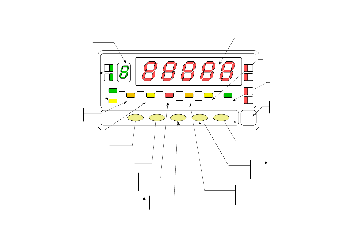
Custom CONFIGURATION for specific applications can be
made quickly and easily through five front panel keys,
following structured choice menus aided by display prompts
at each programming step.
Other features of the KOSMOS family include:
•CONNECTIONS via plug-in terminal blocks without
screws and CLEMP-WAGO clips cable retention system
•DIMENSIONS
Models ALPHA & BETA 96x48x120 mm DIN 43700
Models MICRA & JR/JR20 96x48x60 mm DIN 43700
•CASE MATERIAL UL-94 V0-rated polycarbonate.
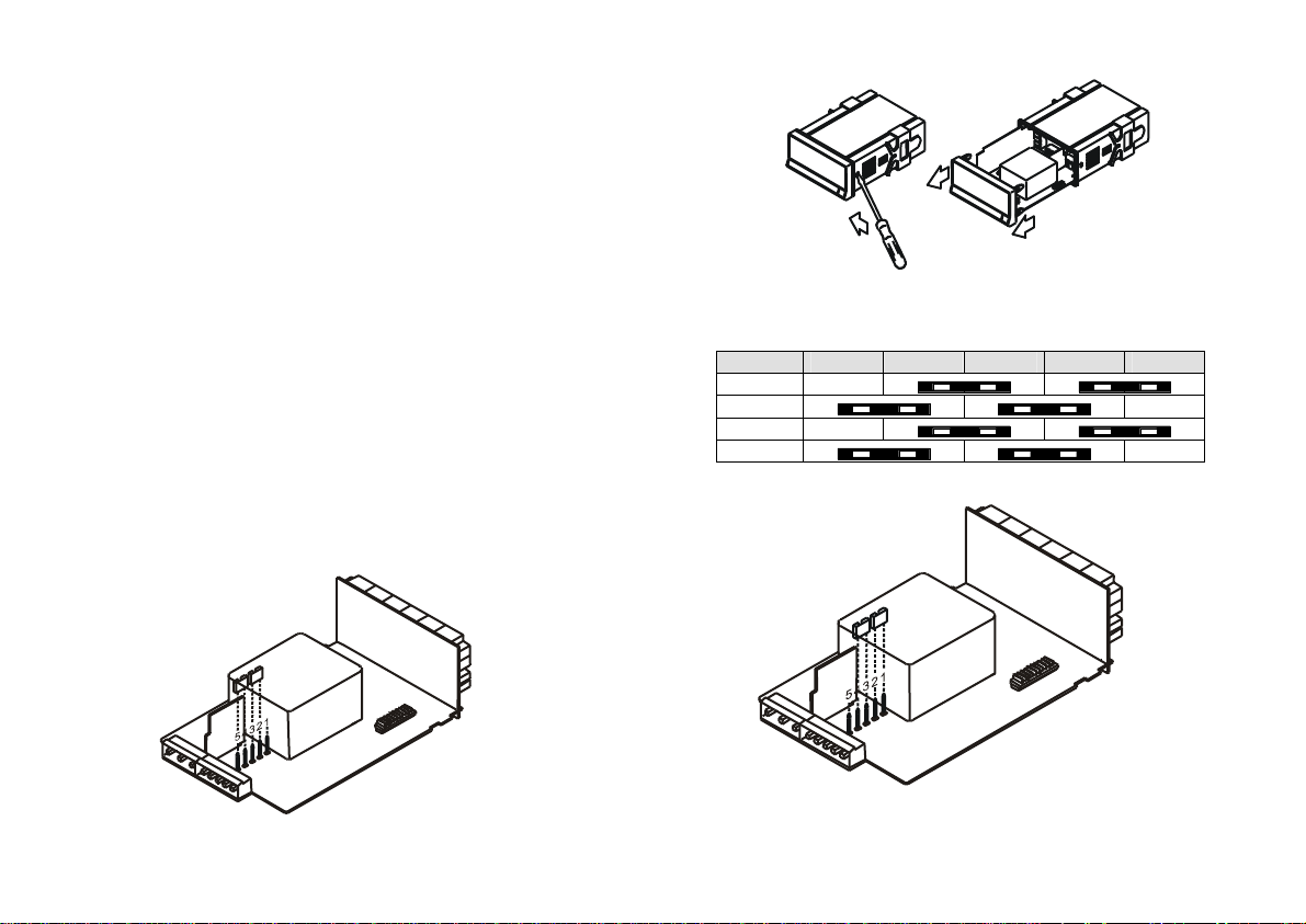
•PANEL INSTALLATION without screws by means of
single part fastening clips
To guarantee the meter's technical specifications, it is
recommended to recalibrate the meter at periodical intervals
according to the ISO9000 standards for the particular
application operating criteria. Calibration should be performed
at the factory or in a qualified laboratory.
This manual does not constitute a formal agreement.
ll information given in this manual is subject to
change without notice.
The KOSMOS SERIES brings a new philosophy in digital panel
instrumentation which is expressed by multipurpose,
modular-concept devices providing a rich array of basic
functions and advanced capabilities.
With a fully MODULAR DESIGN, it is possible to implement a
wide variety of applications by only adding the adequate
options.
Intelligence within it allows the instrument to recognize the
options installed and ask for the necessary parameters to
properly function within desired margins. The parameters
related to non-installed options are removed from the
program routines.
The instrument’s CALIBRATION is made at the factory
eliminating the need for adjustment potentiometers.
Any circuit or option liable to be adjusted incorporates a
memory where calibration parameters are stored, making it
possible the optional cards be totally interchangeable without
need of any subsequent adjust.
INTRODUCTION TO THE KOSMOS SERIES
Custom CONFIGURATION for specific applications can be
made quickly and easily through five front panel keys,
following structured choice menus aided by display prompts
at each programming step.
Other features of the KOSMOS family include:
•CONNECTIONS via plug-in terminal blocks without
screws and CLEMP-WAGO clips cable retention system
•DIMENSIONS
Models ALPHA & BETA 96x48x120 mm DIN 43700
Models MICRA & JR/JR20 96x48x60 mm DIN 43700
•CASE MATERIAL UL-94 V0-rated polycarbonate.
•PANEL INSTALLATION without screws by means of
single part fastening clips
To guarantee the meter's technical specifications, it is
recommended to recalibrate the meter at periodical intervals
according to the ISO9000 standards for the particular
application operating criteria. Calibration should be performed
at the factory or in a qualified laboratory.