MT-KOS1720_EN_20181217 User instruction guide
KOS1720 USER GUIDE To avoid the risk of electric shock and fire, read this instruction document completely before using it..
Dual channel signal conditioner designed to accept RTD, Thermocouple or Potentiometer sensors and provide isolated, industrial process output signals in mA or
Volts. Each output channel may be linked to either input sensor or to a maths function of both sensor signals. This powerful feature allows the device to operate in a
number of different modes.
DISEÑOS Y TECNOLOGÍA S.A., Xarol, 6B, P.I. Les Guixeres, 08915 Badalona, ESPAÑA. www.ditel.es
+34 933 394 758.
IMPORTANT SAFETY REQUIREMENTS.
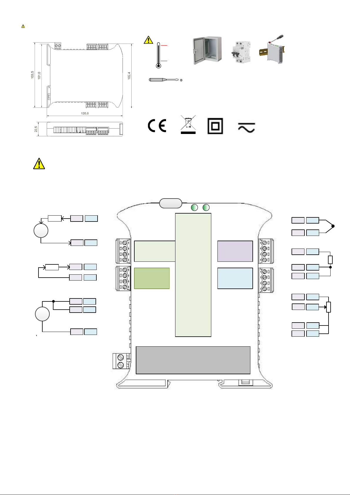
Max working voltage Terminals (101 to 104) and (201 to 204) Inp ts ±24 Vdc @ 10 mA
Max working voltage Terminals (105 to 108) and (205 to 208) O tp ts ±30 Vdc @ 50 mA
Max working voltage Terminals (S1 to S2) s pply 240 Vac, ± 240 Vdc
Isolation s pply to Inp t/o tp t 4200 V
Any inp t to any O tp t 3750 V
O tp t to O tp t, Inp t to Inp t 3750 V
•This eq ipment is s itable for environment Installation category II poll tion degree 1 and is classed as "PERMANENTLY CONNECTED
EQUIPMENT". The eq ipment is intended for ind strial and commercial application only and not s itable for domestic or medical se.
•The eq ipment m st be mo nted inside an enclos re that provides protection >= IP65. In NORMAL USE, the eq ipment will only be accessed
for maintenance by q alified personnel. Please ens re the eq ipment is mo nted vertically with terminals (101 to 204) at the bottom. This
will provide maxim m ventilation and correct cold j nction compensation. This eq ipment may generate heat, ens re the enclos re size is
adeq ate to dissipate heat. Be s re to consider any other eq ipment inside the enclos re.
•The eq ipment s rfaces may be cleaned with a damp cloth. Use a mild detergent/water on a damp cloth. Ens re the s pply is off before
cleaning and on completion of cleaning the eq ipment is completely dry before the s pply is t rned back ON.
•The eq ipment contains no serviceable parts, or internal adj stments. No attempt m st be made to repair the prod ct. Fa lty eq ipment
m st be ret rned to the s pplier for repair.
•This eq ipment m st be installed by a q alified person. All electrical wiring m st be carried o t in accordance with the appropriate
reg lations for the place of installation.
•DC s pply m st be derived from a local s pply and not a distrib tion system.
•To maintain CE EMC req irements, voltage inp t, DC s pply and voltage o tp t wires m st be less than 30 metres.
•S pply (20 to 240) Vac 50/60 Hz (20 to 240) Vdc. If s pply is a HAZARDOUS VOLTAGE a s pply isolation switch m st be installed close to
the eq ipment with the “OFF” position clearly marked. Also, the s pply m st be f sed with a s itable 1 A (T) f se (circ it breaker) installed
close the eq ipment.
•Receipt and npacking. Please inspect packaging and instr ment thoro ghly for any signs of transit damage. If damage is present, do not
se the eq ipment as safety protection may be affected. Please ret rn damaged eq ipment to s pplier.
•USB config ration can be performed witho t the s pply being connected. For safety reasons, se 24 Vdc for f nctional test of nit prior to
fixed installation. The following operations sho ld only be carried o t on a disconnected device and nder ESD safe conditions: General
mo nting, connection and disconnection of wires.
Specification, please refer to s pplier’s web site latest prod ct data sheet for f ll specification.
Basic specification
Supply (20 to 240) Vac 50/60 Hz or (20 to 240) Vdc, 3 W, max isolation 4.2 KV supply to input output
3.75 KV to all other ports
Input (SELV) RTD, Thermocouple, Potentiometer.
Output (SELV) Current (0 to 20) mA, Voltage (0 to 10) V
Ambient (-20 to 70) °C Approvals EN61010_1, EN61326
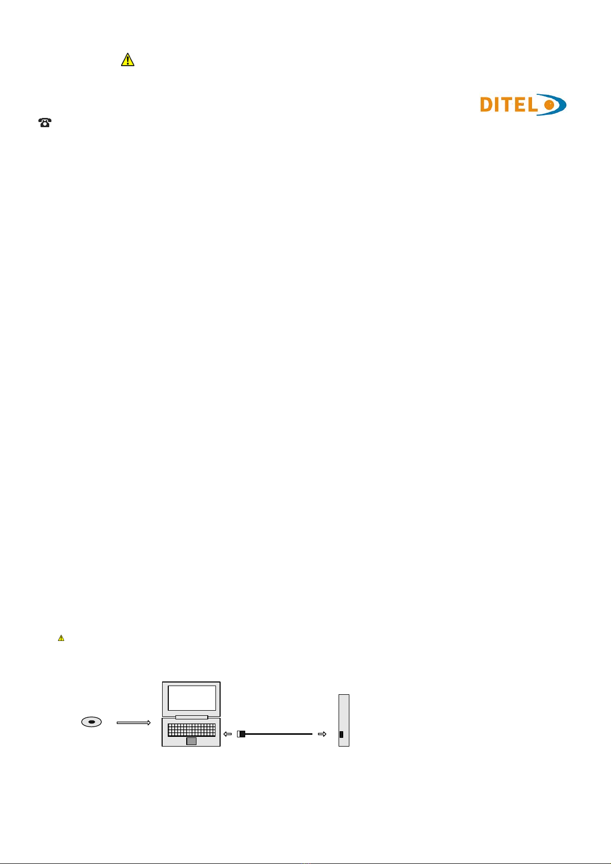
Config ration (Read the IMPORTANT SAFETY REQUIREMENTS) During configuration the equipment takes its po er from the USB port, therefore
no po er supply connection is required. The equipment can be configured hilst po ered but the computer used must be isolated from the supply earth to
avoid grounded earth loop effects. To avoid electric shock only use a 24 Vdc supply during bench configuration.
Device
USBSpeedLink software
www.stat s.co. k
USB CABLE
COMPUTER
Default settings inputs PT100, outputs (4 to 20) mA, process ranges (0 to 100) °C, fail high, Tag Channel 1 Channel 2.
30727725