Dive Gear Express DGX Gears BCI Backup Regulator User manual
DGX Gears BCI Backup
Regulator Service Manual

Copyright © 2022 Dive Gear Express
All Rights Reserved.
Revision 1 Published 10/28/2022
Revision Date Changes
110/28/2022 Initial publication

1. Overview
(1) The availability of subassemblies and components, repair parts, specialized tools, and maintenance
manuals does not imply qualification to assemble and/or service scuba equipment. Improper service
of dive equipment can lead to severe injury or death. Dive Gear Express recommends that non-qualified
individuals seek professional training/mentoring before attempting repairs or servicing on any diving
equipment.
Failure to follow the procedures outlined herein may result in injury or death!
(2) In the following pages will be found the disassembly, assembly, tuning and troubleshooting steps
for these components. Photos are used throughout to illustrate the procedures.
Please pay special attention to all Caution Notes!
(3) Whenever an item of extra importance needs to be observed, a “Caution Note:” will appear, followed
by the required information. See below.
Caution Note: This must be read and followed!
(4) Included in this manual is a list of recommended/required tools for each disassembly, assembly,
and testing section. They are identified in each section where they are used.
(5) A schematic diagram is located at the rear of this manual. The diagram contains the detailed parts
lists. The diagram also includes the torque specifications for parts where required.
(6) A general troubleshooting guide with space for notes is also included for those using a printed
version. Those who prefer an electronic version should keep detailed notes in an accessible location
for their own observations and service tips, as well as a record of service.
(7) Throughout the text, parts are referenced using the item number on the schematic to facilitate
locating each individual component.
(8) Parts should not be taken out of their packaging until the actual assembly stage is reached, and the
user is ready to lubricate, where necessary, and install them.
(9) Ensure the service area is free of any environmental factors that may cause problems during the
service of your regulators. The area must be clean and organized. The use of nitrile gloves is highly
recommended for final rinsing and assembly. This will minimize the risk of skin oils contaminating the
internal components of the regulator.
(10) Ensure that all required servicing/testing air supplies are available and at the proper test pressures
if not using a regulated supply from a single source. “Modified Grade E” air as typically delivered at a
dive shop fill station is preferred.
Caution Note: Only use air from a breathing air source! Do not use a hardware
store shop compressor.

Cleaning and Rinsing - General Considerations
(11) Cleaning and rinsing of components should be done using clean, fresh water.
(12) Only use degreasers that leave no organic residue (e.g., Extreme Simple Green , Blue Gold Cleaner,
or any clear liquid dish soap that does not contain scents or dyes).
(13) To remove corrosion, use a 50/50 vinegar/water solution and nylon brushes. Areas of heavy
corrosion not removed with vinegar can be addressed with mild phosphoric acid solutions available
from scuba supply houses.
(14) Allow parts to air dry without the use of loop-weave cloths that may leave fibers.
(15) Once all service procedures have been completed and bench testing done, in-water testing in a
confined environment such as a swimming pool is recommended to confirm proper function before
taking the regulator on an actual dive.

Cleaning of Regulator Parts
(16) Cleaning of parts that are going to be reused is one of the most critical steps in servicing the
regulator. As was stated earlier, use the proper solutions for the job at hand. Removal of hydrocarbons
and debris should be accomplished before attempting removal of corrosion. Areas of corrosion are
often also coated with old lubricant or oily contaminants. Before attempting to remove corrosion, use
warm detergent and a soft brush to remove oils and debris. Then use an acidic solution to remove
corrosion. Once corrosion has been removed, inspect parts and repeat detergent washing as needed.
Wearing nitrile gloves throughout the process reduces the risk of contaminating the parts with skin oils.
(17) First, prepare a warm solution of detergent from the list above. Immerse both plastic and metal
parts and agitate thoroughly. Protect critical delicate parts (such as the Crown Orifice) by washing them
separately or isolating them in a small plastic container with holes. Wash the diaphragm separately,
using your fingertips to remove debris. Use a soft nylon brush and/or soft rags soaked in detergent to
scrub away visible debris and contaminants. Corrosion will likely not be removed during this step. Rinse
repeatedly in clean water.
(18) Now address visible corrosion by submerging metal parts only in a 1:1 dilution of white vinegar
and hot water. Do not immerse plastic parts in an acid bath - it will degrade the plastic and make it
more susceptible to cracking. Agitate the parts occasionally and allow parts to stand in the acidic
solution for ten minutes. Wearing gloves, remove and inspect parts, and reimmerse them for an
additional ten minutes if visible corrosion is still noted. Removal of corrosion will leave bare brass
behind, which will not affect regulator function, but will necessitate more frequent future inspection
and service. After the acid bath, rinse all metal parts thoroughly.
(19) Best practice is to neutralize any possible residual acid remaining in crevices and threads, by
immersing all acid-treated parts in a neutralizing solution of warm water and sodium bicarbonate
(baking soda) in a ratio of 1 tablespoon per gallon of water. After a brief neutralizing soak, again rinse
all parts thoroughly. In areas with high mineral content in the water, a final rinse with distilled water
should be considered. A plastic colander is excellent for drainage after rinsing. For very small parts, a
mesh strainer for sink drains works well. Often sold as a set, they are inexpensive and can be used for
many types of regulator components. Again, protect delicate parts from contact with hard metal
surfaces. Retained final rinse water should be allowed to stand and examined for a surface sheen
indicative of residual hydrocarbon residue. If noted, return to step (17) above.
(20) After washing and rinsing the regulator parts, allow them to air dry. Using a drying rack will facilitate
this. Do not lay the parts on a paper towel or loop-weave cloth towel. Doing so runs the risk of having
fibers stick to them that will cause issues with sealing. If a cloth is used as an aid to drying, make sure
to use a tight, flat weave lint-free cloth that has previously been well washed to remove fabric sizing.

Inspection After Cleaning
(21) Before assembling the regulator, it is necessary to inspect all the cleaned components. Using a
magnifying glass or inexpensive USB microscope, ensure all parts are clean and contaminant-free, and
check the components for damage that may have been hidden by corrosion or lubricant. Look for
scratches that may affect the sealing surfaces of the regulator.
(22) Lay all parts out on a padded work surface following the schematic. A rubber or silicone mat of
suitable size that is clean and free of contaminants works well for this.
(23) Now that all parts have been cleaned and checked, the assembly can begin. Remove the new parts
from the service kit bag and lay them out following the schematic, matching them to the old parts for
size. Then make sure all old parts that are to be replaced have been discarded or segregated.
Caution Note: Removing parts from their packaging, before they are to be used,
runs the risk of mixing them up. Some O-rings are very close in size but are not
interchangeable! Keep the parts in their packaging until you are ready to
exchange them for their used equivalent.
(24) As with the parts that have been cleaned, it is a good idea to inspect the new parts as well. Inspect
the LP Seat to ensure it is free of any defects. Check all the O-rings and inspect them as you use them
for nicks or imperfections. Inspect the washers to ensure they are free of burrs or other defects that
could affect their function. It is critical to use the parts list on the schematic to ensure that all new parts
are present and accounted for in their required quantities.
(25) Lubrication can be overdone.Doing so runs the risk of trapping excess dirt or debris on the parts.
One way of reducing the risk of overdoing it is to use the lube-in-a-bag method - Fig. 1
Fig. 1
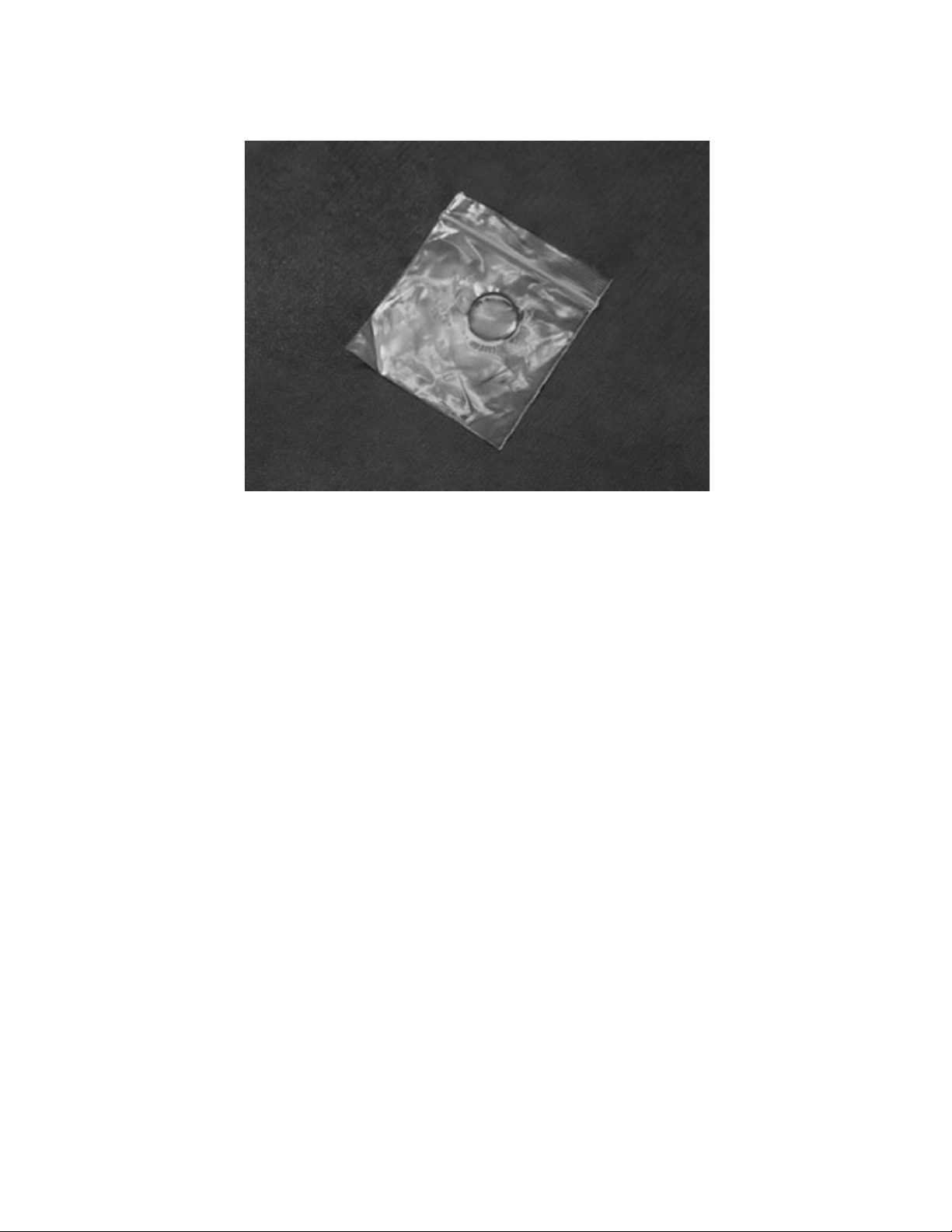
This involves using a small clean plastic bag containing a small amount of lubricant. The O-ring is
inserted into the bag, worked around to evenly coat with lube while squeezing off excess, then taken
out of the bag and used in its location - Fig. 2.
Fig. 2
(26) Another way is to apply a small amount of lubricant to the gloved index finger and massage the O-
ring between the thumb and index finger.
(27) Under most circumstances, a lubricant should be used very sparingly or not at all. In nearly all
scuba applications, if you can see the lubricant, too much has been applied. Before using any lubricant,
any existing lubrication should be removed before new is applied. In dynamic applications, it is used to
reduce excessive wear. Static O-rings do not generally require the use of lubricant.
(28) Do not unnecessarily lubricate parts. Certain parts are specifically noted to be installed without
lubrication. It also helps to keep those parts clean and free of debris that will cling to the lubricant. Not
lubricating unnecessarily helps to keep those parts clean and free of debris that might otherwise cling
to the lubricant.

2. Tool List - Fig. 3
1. Magnehelic or Other Cracking Effort Gauge
2. Thin Wooden Dowels
3. Thin Brass and Heavy Nylon Picks
4. Scuba Tools Double Hook O-Ring Pick
5. Blunt Brass Pick and Blunt Brass Spade
6. Heavy 90° Circlip Pliers
7. Coin - (US Nickel is best diameter/thickness)
8. Stubby Slotted Screwdriver
9. 5/32” Slotted Screwdriver
10. 5.5 mm Nut Driver
11. 13mm Open End and Adjustable Wrench
12. Side-Cutting Snips
13. Scuba Tools Spider 2 Tool
14. 3/16” and 1/16” Hex Keys
15. Tribolube 71
Fig. 3
(1) A Brass O-Ring Pick Set can be found at Dive Gear Express using the link below.
https://www.divegearexpress.com/tools/scuba-tools
(2) Tools may also be purchased from Scuba Tools at the link below.
www.scubatools.com
(3) Additional useful items are a magnifying glass or inexpensive USB microscope, nitrile gloves and,
to aid in rinsing, a plastic colander and small mesh strainers for smaller parts.

3. Preliminary Testing
(1) Preliminary testing of the regulator is necessary to identify any problems and verify the overall
regulator and BCD valve function. This testing will include:
1. Visual inspection of the regulator
2. Inspection of the hoses
3. Cracking effort and negative pressure test
4. Inflation and exhaust valve tests
Visual inspection is done to identify issues that could affect servicing and to ensure that pressurizing
the system will not compromise the safety of the service technician.
Check all connections to make sure they are secure.
Check that on the first stage, there are no extruded O-rings, and hoses are tight.
Detailed inspection of hoses is done to ensure it is safe to pressurize the regulator set. Look for
evidence that might lead to hose failure. Check all hose connection crimps. Defects must be taken care
of before pressurizing the system! Replacement of any suspect hoses is recommended.
Caution Note: Defects in hoses require replacement before pressurizing the
regulator! Failure to do so may result in serious injury!
(2) The Intermediate Pressure (IP) of the first stage should be confirmed before testing the backup
regulator.
(3) The standard operating range for the system is with an IP of 135 psi.

4. Regulator Evaluation
(1) The negative pressure test verifies the seals of the Diaphragm and Exhaust Valve, confirms proper
O-ring seal and verifies housing integrity. With the supply pressure off, and attached to a first stage on
a cylinder, attempt a normal breath from the backup regulator. You should be unable to draw any air. If
flow is obtained, remove the regulator from the hose and try to draw air while sealing the hose inlet
with your finger. If a flow is still present, the Diaphragm and Exhaust Valve need to be checked for
damage. Salt accumulation, sand, and defects in the housing or O-rings may also allow airflow when
the air inlet is covered. Carefully check all of these.
(2) Cracking effort testing is most accurately done with the use of a magnehelic gauge. A container of
water can be used by measuring the depth to which a stage can be submerged face-down parallel to
the water. This gives an indication at which level of effort the second stage will open. The normal range
for the BCI Backup Regulator is 1.4 to 1.9 inches of water. Less pressure may be desired by the diver,
but the minimum initial factory setting of at least 1.4 should be used. This permits a break-in period for
the LP seat. It is normal to see this initial setting drop as the LP seat takes a set.
(3) The housing should be inspected for signs of damage. Scratches, gouges, missing parts, a damaged
exhaust port or a loose Retainer Ring may be indications of a damaged housing.
(4) After the negative pressure test, test the purge button, and confirm brisk airflow. Check Inflation
Button and Oral Button movement. Do they move freely and with no indication of stiffness? Do they
feel like there is sand or grit in them? With the regulator attached to a BCD, confirm that the Inflation
Button quickly inflates the BCD, and that the exhaust valve stays closed until the Oral Button is
depressed.
(5) A problem with housing integrity should be dealt with before starting the rebuild. A defective housing
will compromise final testing and pose a safety hazard to the user.
Caution Note: A damaged Main Body, Purge Cover, or Diaphragm cannot be
repaired. They must be replaced.
(6) Having completed the initial evaluation and determined that service is necessary, the rebuild of the
regulator can take place.

5. Regulator Disassembly
(1) Ensure the system is depressurized. The use of small, clean containers to hold parts is
recommended.
(2) In the following steps, the part numbers from the schematic will be used with their description. The
numbers on the photos also correspond with the parts list on the schematic. Items in the service kit
are identified in the same way. Have the schematic in front of you while following the instructions. Be
sure to keep all old parts organized and separate from new ones in the service kit. The old washers and
O-rings marked with an asterisk (*) will be replaced with new ones from the service kit and the
remaining parts will be cleaned and reused.
1. Unscrew the threaded collar of the Hose Connector Assembly (01) from the Main Body (08), using
an adjustable wrench to loosen if necessary. Remove O-ring (04*) using a heavy nylon pick - Fig. 4.
Fig. 4
2. Using side-cutting snips, remove the tie wrap(s) securing the corrugated hose to the Hose Connector
Assembly. Using a brass spade, loosen the seal of the hose and work it off. If a pull dump cable is used,
use a 1/16” hex key to push out the Retainer Pin (05).
3. Using side-cutting snips, cut the Tie Wrap (44) holding the Mouthpiece (25). Peel off the mouthpiece,
inspecting it for cuts or tears.
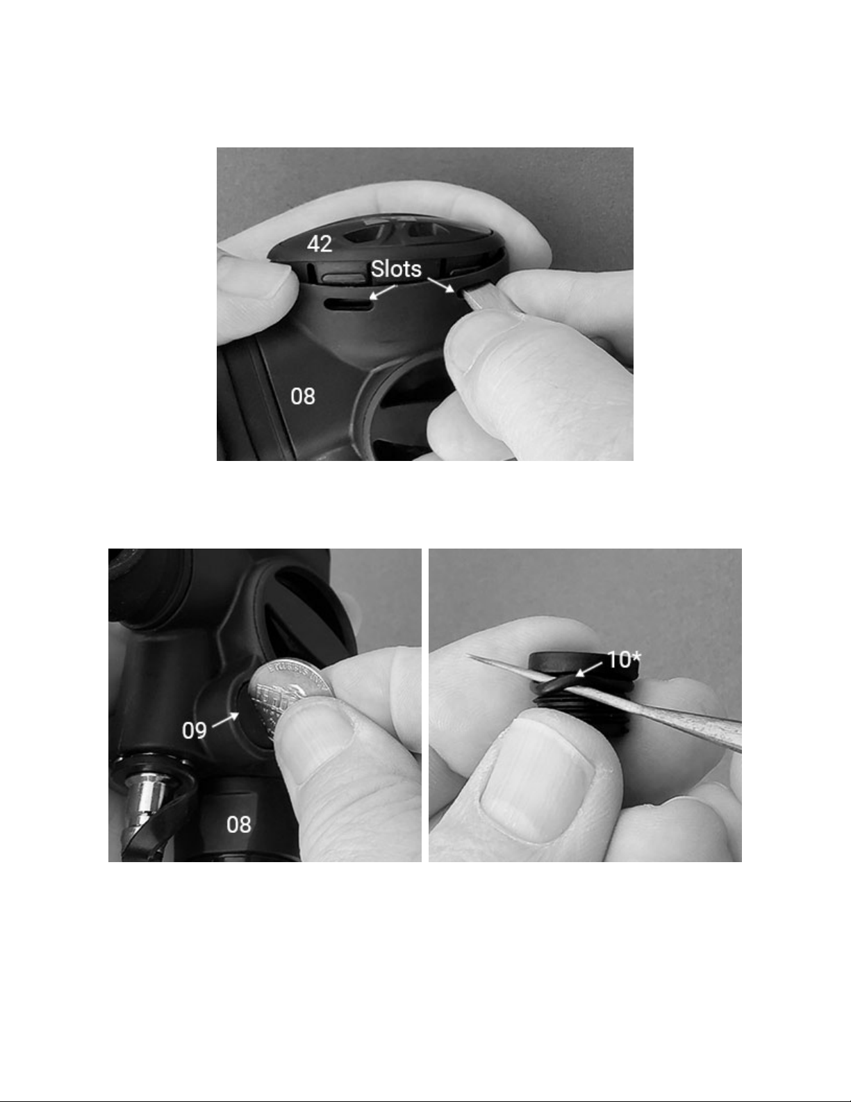
4. Unlock the Retainer Ring (42) by depressing all four tabs in the slots in the Main Body with a stubby
slotted screwdriver - Fig. 5. Remove the purge cover assembly consisting of the Retaining Ring (42),
the Purge Cover (41) and the Diaphragm Washer (40). Run a blunt brass spade around the rim to break
any seal between the Diaphragm (39) and the Main Body. Remove the Diaphragm.
Fig. 5
5. Insert a U.S. nickel or other suitable coin in the slot in the Threaded Cap (09) and unscrew it
completely - Fig. 6. Use a thin brass pick to remove its O-ring (10*) - Fig. 7.
Fig. 6 Fig. 7
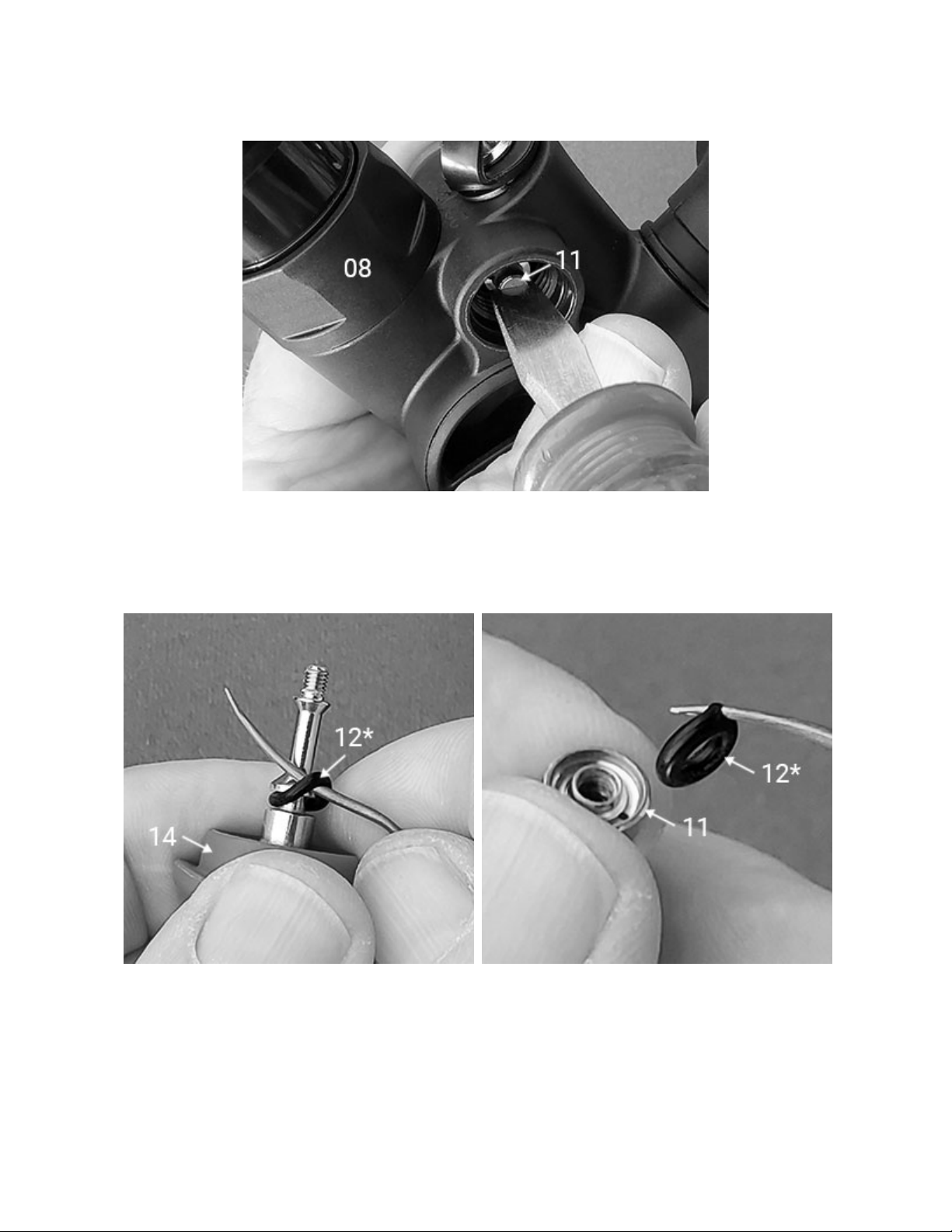
6. Maintaining pressure on the Inflation Button (14), use a flat-bladed screwdriver in the slot in the Cone
Seat (11) to unscrew it completely - Fig. 8. Releasing pressure on the Inflation Button, remove the
Inflation Button assembly from the Main Body. Remove the Spring (13).
Fig. 8
7. Using a thin brass pick, remove O-ring (12*) from the shaft of the Inflation Button - Fig. 9. The metal
shaft of the Inflation button is permanently bonded to the plastic top - do not try to separate. Use a thin
brass pick to pry out the sealing O-ring (12*) from the Cone Seat - Fig. 10.
Fig. 9 Fig. 10
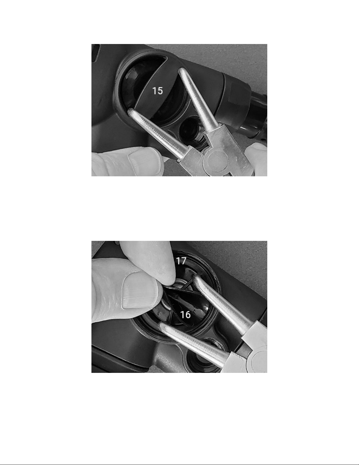
8. Using the tips of heavy 90° circlip pliers set on either side of the center bar in the Exhaust Cover (15),
loosen the cover, then unscrew and remove it by hand - Fig. 11.
Fig. 11
9. Carefully lift the edges of the Exhaust Valve and insert the circlip pliers on opposite sides of the two
spokes in the Exhaust Retainer (17) - Fig. 12. After loosening the Exhaust Retainer, remove it completely
with your fingertips. Inspect the Exhaust Valve (16) for damage. It is not necessary to remove the
Exhaust Valve from the Retainer during routine service if it is undamaged and the edge seals against
the rim.
Fig. 12

10. Use a thin brass pick to remove the Exhaust Retainer O-ring (18*) - Fig. 13.
Fig. 13
11. While maintaining pressure on the Oral Button (24), and using a 5.5 mm nut driver, unscrew and
remove the Nut (19*) from the center of the Exhaust Seal (20) - Fig. 14.
Fig. 14

12. Release pressure on the Oral Button and remove the Exhaust Seal - Fig. 15. Inspect its edges for
cracking or damage.
Fig. 15
13. Remove the Oral Button assembly from the Main Body and separate its four parts: Oral Button (24),
Spring (23), Washer (22) and O-ring (21*) - Fig. 16. The O-ring may be retained in the Main Body. If so,
extract it with a plastic pick.
Fig. 16
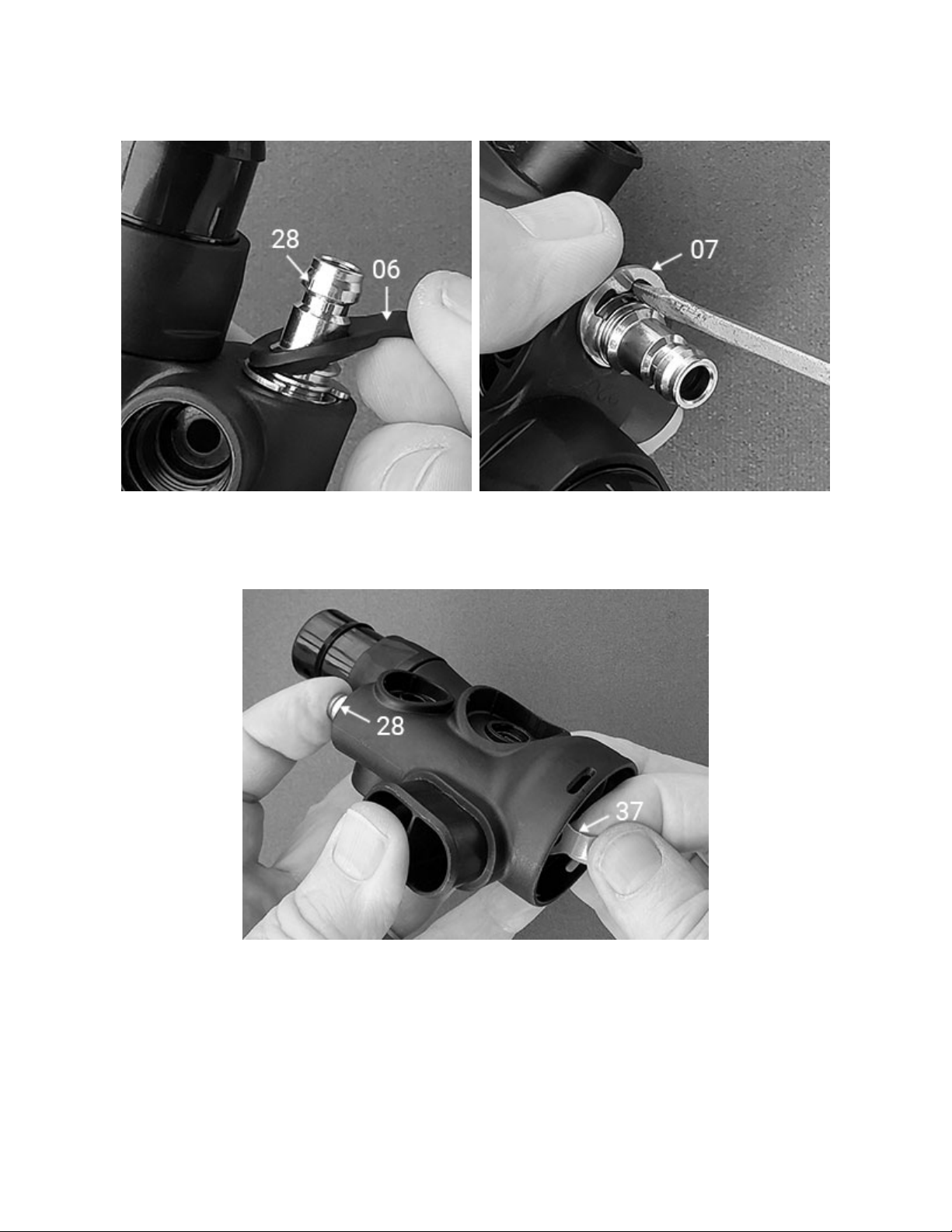
14. Stretch the Dust Cap (06) away from the Inlet Stem (28) until it is free of its groove and slide it off -
Fig 17. Insert a 5/32” flat-bladed screwdriver in the slot in the C-Clip (07) between it and the Inlet Stem
(28) and twist the screwdriver so that the clip is forced out - Fig 18.
Fig. 17 Fig. 18
15. Grasping the valve assembly by the Lever (37), and pressing on the Inlet Stem (28), pull the valve
assembly out of the Main Body from the Lever end - Fig. 19.
Fig. 19
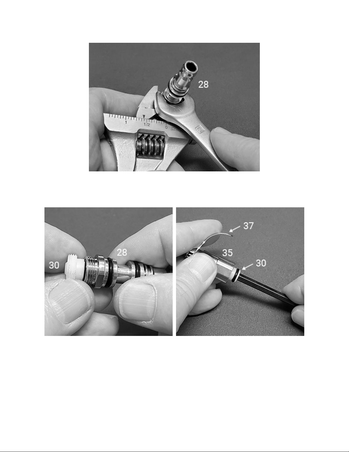
16. Using a 13mm open-end wrench set against the thin flats of the Inlet Stem (28), and an adjustable
wrench attached to the flats on the Valve Housing (35), loosen and unscrew the two parts - Fig. 20.
Fig. 20
17. Pull the Crown Orifice (30) straight out of the Inlet Stem – Fig 21. If it remained behind inside the
Valve Housing, apply pressure to the Lever and unscrew it completely with a 3/16” hex key – Fig. 22.
Fig. 21 Fig. 22

18. Using a thin brass pick, remove the O-ring (29*) from the Crown Orifice, protecting the knife edge
from contact with metal parts,and remove both O-rings (27*) from the Inlet Stem.
19. Thread the Spider 2 tool into the Valve Housing and screw it in until the lever just begins to drop -
Fig. 23. Using a 5.5 mm nut driver, unscrew the Nut (19*), then remove the Washer (38) and Lever (37)
- Fig. 24.
Fig. 23 Fig. 24
20. Unscrew the Spider 2 tool. Noting that the Seat assembly is under tension from the Spring (34),
remove the Seat assembly and Spring. Slide back the Seat Retainer (33) and remove the Seat (31*) and
Stem (32) - Fig. 25. Using a fingernail, remove the Housing Insert (36) from the Valve Housing - Fig. 26.
Fig. 25 Fig. 26
This completes disassembly of the BCI Backup Regulator.
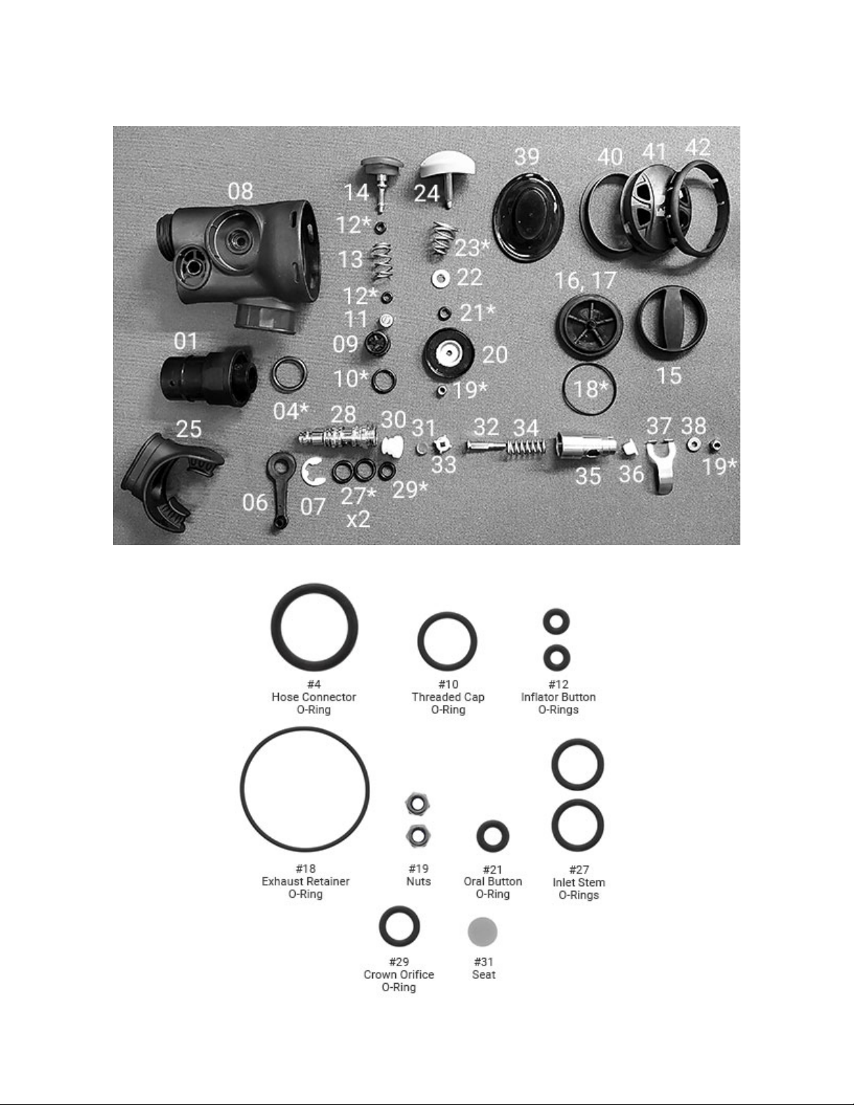
(3) The photographs below show the disassembled regulator - Fig. 27 - and Service Parts Kit - Fig. 28.
All the parts not in the service kit need to be washed, rinsed and dried, as discussed previously. O-rings
and washers that will be replaced with new from the service kit should be discarded.
Fig. 27
Fig. 28
Table of contents
Other Dive Gear Express Diving Instrument manuals

Dive Gear Express
Dive Gear Express XTRA Second Stage User manual

Dive Gear Express
Dive Gear Express DGX Gears XTRA User manual

Dive Gear Express
Dive Gear Express DGX Gears FIRST User manual

Dive Gear Express
Dive Gear Express DGX Xtra First Stage User manual

Dive Gear Express
Dive Gear Express DGX Gears D6 User manual


