Dive Gear Express DGX Xtra First Stage User manual
DGX Gears XTRA Regulator
Service Manual
DGX Xtra First Stage

Copyright © 2020 Dive Gear Express
Author/Photographer – UDM Consulting
All rights reserved.
Revision 5d Published 8/17/2020

1.Overview
(1) The availability of subassemblies and components, repair parts, specialized tools, and maintenance
manualsdoesnotimplyqualificationtoassembleand/orservicescubaequipment.Improperserviceofdive
equipmentcanleadtosevereinjuryordeath.DiveGearExpressrecommendsthatnonqualifiedindividuals
seekprofessionaltraining/mentoringbeforeattemptingrepairsorservicingonanydivingequipment
Failuretofollowtheproceduresoutlinedhereinmayresultininjuryordeath!
(2)Inthefollowingpageswillbefound,thedisassembly,assembly,tuning,andtroubleshootingstepsfor
thesecomponents.Photosareusedthroughouttoillustratetheprocedures.
Pleasepayspecialattentiontoallcautionnotes!
(3)Wheneveranitemofextraimportanceneedstobeobserved,a“CautionNote:”willappear,followedby
therequiredinformation.Seebelow.
CautionNote:Thismustbereadandfollowed!
(4) Included in this manual is a list of recommended/required tools for each disassembly, assembly, and
testingsection.Theyareidentifiedineachsectionwheretheyareused.
(5) Schematics are located inthe rear of this manual. The drawings containthe detailed parts lists. The
drawingsalsoincludethetorquespecificationsforpartswhererequired.
(6)Ageneraltroubleshootingguidewithspacefornotesisalsoincludedforthoseusingaprintedversion.
Thosewhopreferanelectronicversionshouldkeepdetailednotesinanaccessiblelocationfortheirown
observationsandservicetips,aswellasarecordofservice.
(7)Throughoutthetext,partsarereferencedusingtheitemnumberontheschematictofacilitatelocating
eachindividualcomponent
(8)Photographsofthepartskitsareshowntoillustratethateachcomponentisindividuallybagged.Parts
shouldnotbetakenoutoftheirpackaginguntiltheactualassemblystageisreached,andtheuserisready
tolubricate,wherenecessary,andinstallthem.
(9) Ensure the service area is free of any environmental concerns that may cause problems during the
servicing of your regulators. The area must be clean and organized. The use of nitrile gloves is highly
recommendedforthefinalrinsingandassemblystages.Thiswillminimizetheriskofskinoils,contaminating
theinternalcomponentsoftheregulator.
(10)Ensurethatallrequiredservicing/testingairsuppliesareavailableandatthepropertestpressures,if
not using a regulated supply from a single source. This would include the use of cylinders of compressed
breathing air from an OCA grade source if you wish to maintain the oxygenclean status of the unit.
CautionNote:Onlyuseairfromabreathingairsource!

CleaningandRinsingGeneralConsiderations
(11)Cleaningandrinsingofthecomponentsshouldbedoneusingclean,freshwater.Ifavailable,distilled
waterisrecommendedtomaintainoxygencleanliness.
(12) Only use degreasers that leave no organic residue (clear Simple Green, dyefree Dawn dishwashing
liquid,orBlueGoldCleanerasexamples).
(13)Todealwithcorrosion,usea50/50vinegarwatersolutionandnylonbrushes.
(14)Allowpartstoairdrywithouttheuseofclothsthatmayleavefibers.Forregulatorsthataregoingtobe
used with Oxygen percentages above 40%, a UV light is strongly recommended to check for organic
contamination.
(15)Onceallserviceprocedureshavebeencompletedandbenchtestingdone,inwatertestinginaconfined
environment such as a swimming pool is recommended to confirm proper function before taking the
regulatoronanactualdive.
CleaningofRegulatorParts
(16)CleaningCleaningofthepartsthataregoingtobereusedisoneofthemostcriticalstepsinservicing
theregulator.Aswasstatedearlier,usethepropersolutionsforthejobathand.Vinegarandwaterarenot
asusefulforremovinglubricatinggreaseasoneofthedetergentsthatwerenoted.Bythesametoken,
thosedetergentsarenotasefficientasthevinegar/watermixindealingwithcorrosivebuildup.
(17)Therefore,whereyouhaveabuildupofcorrosion,youmayalsohavelubricantonthesurfaceofthe
part.Beforedealingwiththecorrosion,usehotsoapywaterandasoftbrushtoremovethelubricant.Then
usetheacidicsolutiontodealwiththecorrosion.
(18)Oncethecorrosionhasbeendealtwith,washthepartsusingafreshsoapandwatersolutionwhile
wearingnitrileglovestoreducetheriskofcontaminatingthepartswithskinoils.Rinsethepartswithclean
runningwater,distilledispreferred,thatisallowedtodrainfreely.Aplasticpastacolanderavailableatany
storeisexcellentforthis.Forverysmallparts,ameshstrainerforsinkdrainsworkswell.Oftensoldasa
set,theyareinexpensiveandcanbeusedformanytypesofregulatorcomponents.Seethephotographsof
eachinthetoolsection.
(19)Afterwashingandrinsingtheregulatorparts,allowthemtoairdry.Usingadryingrackwillaidinthis,
aswellashavingtheairintheroomcirculating.Donotlaythepartsonapaperorclothtowel.Doingsoruns
theriskofhavingfiberssticktothemthatwillcauseissueswithsealing.Inadditiontothis,fiberscanbea
hazardwhenusingtheregulatorwithhighoxygencontentmixes.
(20)Oncethepartshavedriedcompletely,laythemoutinorderofassemblyonthepadusedonthework
surface.Makingsurethatithasbeencleanedandisfreeofcontaminants.Arubberorsiliconematofsuitable
sizeworkswellforthis.Youcanalsousesmallcleancontainerstokeepthepartsorganized.Oncetheparts
have beencleanedand dried,theyneed to beinspected beforestarting theassemblyprocess.Thisis to
ensure that no damage or defects exist that were hidden by corrosion, residual lubrication, or other
contaminantsthathavenowbeenremoved.

InspectionAfterCleaning
(21)Beforeassemblingtheregulator,itisnecessaryto inspectallofthecleaned components. Usingthe
magnifyingglass,checkthecomponentsfordamagethatmayhavebeenhiddenbycorrosionorlubricant.
Lookforscratchesthatmayaffectthesealingoftheregulator.Inadarkenedroom,usetheUVlighttolook
fororganicmaterial.Ifanyarepresent,recleanthepart!Thisiscriticalforusewithoxygenpercentages
above50%!
(22)Anotherwaytocheckforresiduallubricantsistofillatraywithclean,fresh,waterdeepenoughtocover
thepartsbyaninchorso.Laythecomponentsinandcirculatethewater.Allowthepiecestosoakforseveral
minutes.Onceithassettled,lookforarainbowsheenonthesurfaceofthewater.Anyresiduallubricants
willfloatandforma“slick”onthesurface.Ifoneispresent,thepartsmustbecleanedagain.
(23)Nowthatallpartshavebeencleanedandchecked,theassemblycanbegin.Makesurealloldpartsthat
aretobereplacedhavebeendiscardedorsegregated.Removethenewpartsfromtheservicekitbagand
laythemoutintheordertheywillbeused.Donottakethenewpartsoutofthebagsyet!
CautionNote:
Removingpartsfromtheirindividualbags,beforetheyaretobeused,runstheriskof
mixingthemup.Someoringsareverycloseinsizebutarenotinterchangeable!Keep
thepartsinthebagsuntilyouactuallyneedthem.
(24)Aswiththepartsthathavebeencleaned,itisagoodideatoinspectthenewpartsaswell.Especially
theHPseat.Makesureitisfreeofanydefects.Checkalloftheoringsandinspectthemasyouusethemfor
nicksorotherconcerns.Inspectthewasherstoensuretheyarefreeofexcessburrsorotherconcernsthat
couldaffecttheirfunction.Itisalsoagoodideatousethepartslistontheschematictoensurethatallofthe
newpartsthatareneededarepresentandaccountedforintheirrequiredquantities.
(25)LubricationofOrings;Lubricationcanbeoverdone.Doingsorunstheriskoftrappingexcessdirtor
debrisontheparts.Onewayofreducingtheriskofoverdoingitistousethelubeinabagmethod.This
involvesusingasmallcleanplasticbagandputtingasmallamountoflubeinit.Thentheoringisinserted
intothebag,workedaround,excesssqueezedoff,andtakenoutofthebag,andusedinitslocation.
Fig.1Fig.2.
(26)AnotherwayistoapplyasmallamountofTribolubetotheglovedindexfingerandmassagetheoring
betweenthethumbandindexfinger.Eitherwayworks,butthebagmethodtendstogivebetterdistribution
resultsanduseslesslubricant.

(27)Undermostcircumstances,alubricantisusedcorrectlyverysparinglyornotatall.Innearlyallscuba
applications, ifyoucan see thelubricant, you’ve usedtoomuch. Before using any lubricant, any existing
lubricationshouldberemovedbeforenewisapplied.Indynamicapplications,itisusedtoreduceexcessive
wear.Staticoringsdonotgenerallyrequiretheuseoflubricant.
(28)Wherepartsarenotnecessarytobelubricated,itisgoodpracticetoavoidgettinganylubricantonthem.
PrimarilywhentheregulatorisusedwithhighO2contentmixes.Italsohelpstokeepthosepartscleanand
freeofdebristhatwillclingtothelubricant.
Thenextsectionliststhetoolsyouwillneedtoservicetheregulator.

2.TOOLLIST
(1) The tool list has been divided into two sections. Required and Recommended. Required tools are
necessaryforservicingtheregulator.Recommendedarethoseitemsthatmakeservicingeasierormore
efficientaswellaslesseningthechanceofdamage.
Requiredtools
1. AdjustableTorqueWrench3/8drive0300inchpoundsrange
2. PistonStemBushingAssemblyTool–ScubaToolspartnumber20150200
3. ScubaMultiTool–ScubaToolspartnumber20100200
4. 1stStageHandleforHPandLPports
5. 3/4inch3/8thdrivesocket
6. 6mm3/8inchdriveHexHeadmalesocket
7. 5mm3/8drivehexsocket
8. 4mm3/8drivehexsocket
9. 2AdjustableWrenches
10. BrassPicksforremovingorings
11. IntermediatePressureGauge
12. Tribolube71
13. SoftBristleCleaningBrushes(Nylon)
Recommendedtools
1.Inlinesecondstageadjustmenttoolwithslottedorificeselected
2.Softjawedvise
3.Woodenorplasticdowels1/8–3/16diameter
4.SoftRubberPad
5.MagnifyingGlass
6.Flashlight
7.UVlight
(2)Whereapartnumberisnoted,ScubaToolsisthesourceofthatitem.Theyalsohavesomeoftheother
toolsnotedbutarenottheonlysupplierofthem.
ScubaTools
www.scubatools.com
Phone:3366432599
(3)YoucanalsopurchasetoolsfromDiveGearExpress.The1ststagehandle,InLineAdjustingToolwithIP
gauge,PinSpanner,BrassPicks,andtheIPGaugethatisshownthatplugsintotheLPinflatorhosecanbe
foundatthelinkbelow.
https://www.divegearexpress.com/tools/scubatools
Phone:9549776009
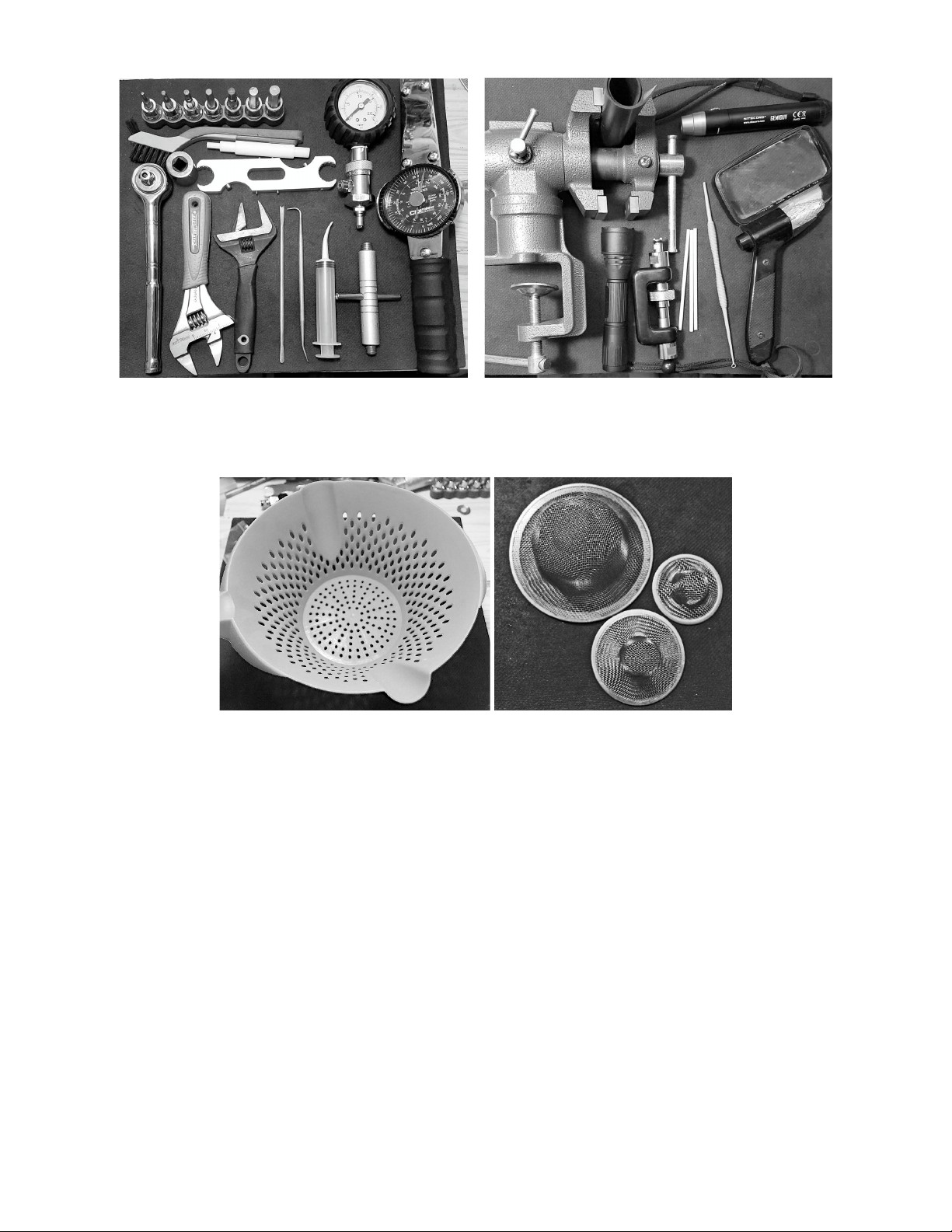
Fig.3Fig.4
RequiredToolsRecommendedTools
Fig.5Fig.6
ColanderStrainers

3.PreliminaryTesting
(1)Preliminarytestingoftheregulatorisnecessarytoidentifyanyissueswiththefirstandsecondstagesand
verifytheoverallregulatorfunction.Thistestingwillinclude:
1. Visualinspectionofthefirstandsecondstages
2. Inspectionofthehoses
3. IntermediatePressurecheck
4. CrackingPressureandSecondStageNegativePressureTest
Visual inspectionisdonetoidentifyissuesthatcouldaffectservicingandtoensurethat pressurizingthe
systemwillnotcompromisethesafetyoftheservicetechnician.
Thetechnicianwillcheckallconnectionstomakesuretheyaresecure.
Thetechnicianwillcheckthatonthefirststage,therearenoextrudedorings,andhosesaretight.
ThetechnicianwillchecktherearenodefectstotheSPG.
ThetechnicianwillensurethattheDINassemblyissecure,andtheOringisintactandabletoformaseal.
Thetechnicianwillinspectthefilterforsignsofdiscoloration.
DetailedInspectionofHosesisdonetoensureitissafetopressurizetheregulatorset.
Thetechnicianwillcheckallhoses,lookingforevidenceofpossiblefailure.
Thetechnicianwillcheckallhoseconnectioncrimps.Defectsmustbetakencareofbeforepressurizingthe
system!Replacementofanysuspecthosesisrecommended.
CautionNote:
Defectsinhosesrequirereplacementbeforepressurizingtheregulator!Failuretodoso
mayresultinseriousinjuryordeath!
(2)DetailedVisualInspectionoftheSPGandconnection–ThetechnicianwillchecktheSPGforanysigns
ofcrackingof theface, waterintrusion,and corrosionaround theSPG to thehose connection.Ifusing a
consoleorboot,itisnecessarytoremovetheSPGfromtherubberboot.Oncethisisdone,theHPspool
shouldbeinspectedand,ifnecessary,replaced.
(3)CheckingofIntermediatePressure(IP)–TheIntermediatePressure(IP)ofthesystemshouldbetested
only after the preceding checks have been done to ensure technician safety. Checking of intermediate
pressureisdonebyattachinganintermediatepressuregaugetotheLPpressureinflatorhose.Thesystemis
thenpressurizedwhilepartiallydepressingthepurgebuttonononeofthesecondstages.Depressingthe
purgebuttonslightlyonthesecondstageisdonetopreventfurtherdamagetothesystembyprovidinga
reliefvalveshouldtheIPriserapidlytounsafelevels.Oncethesystemhasbeenpressurized,thepurgeis
released,andtheIPchecked.

CautionNote:
Ifthesecondstageisleakingevenslightly,IPwillbeaffected.Ifthesecondstageis
leaking,turntheadjustmentknobtostopitoruseasecondstagethatisnotleaking
throughwhenpairedwiththefirststage.
(4)ThestandardoperatingrangeforthesystemiswithanIPof135PSI.Ideally,thesystemisoperatingat
135PSI+/5PSIandshownosignsof“creep”orinstabilityat3000PSI.
CautionNote:
“Creep”willshowastheIPsteadilyincreasingwhiletheregulatorisnotinuse.Normally
theIPwilldrop510PSIduringabreathorpurgeandthenreturntoitssetting.Itshould
notreturntothesettingandkeepincreasing.Thiswouldindicateaproblemwiththe
highpressureseat,Piston,orsealingorings.
(5)IfthesystemshowsnosignofcreeporIPinstability,itisgenerallynotnecessarytorebuildthe1ststage
withsomeexceptions.
CautionNote:
Iftheunitshowssignsofinternalcorrosionorthefiltershowsevidenceofcontamination,
theunitmustberebuilt!RegardlessoftheIntermediatePressure.
(6)Theregulatorwillrequirerebuildingifsmallbubblesareleakingfrombetweentheturretretainerand
mainbody,fromundertherubbercap,oroutofthehighpressureseatretainer.Knowledgeoffloodingof
the first stage will also require the unit to be rebuilt. Freshwater contains dissolved minerals and other
materialsthat,duetointernalcorrosionovertime,maycausetheregulatortomalfunction.
(7)AftertheIPhasbeenchecked,hosesandregulatorbodyinspected,andSPGevaluated,theserviceofthe
1ststagecantakeplaceifitisdeterminedthatserviceisnecessary.

4.FirstStageDisassembly
(1)1ststagedisassembly–Ensurethesystemisdepressurized.Documentthepositionofallhosesandport
plugs.Theuseofsmall,cleancontainerstoholdpartsisrecommended.
(2)Inthefollowingsteps,thepartnumbersfromtheschematicwillbeusedwiththeirdescription.Havethe
schematicinfrontofyouwhilefollowingtheinstructions!Besuretokeepalloldpartsorganizedandseparate
fromnewonesintheservicekit!
1.Removeallhosesandportplugs–Fig.7.
Fig.7
2.RemovetheDINShuttervalve(D2)usinga4mmhexandDINshuttercrown(D4),whichcontainstheSpring
(D6)andtwosmallnylonwashers(D5)–Fig.8.Washersarereplacedasindicatedbythe*symbol.
Fig.8
Thenumbersonthephotocorrespondwiththepartslistontheschematic.Thisisdonetoaidinthe
identificationofindividualitems.Itemsintheservicekitsareidentifiedinthesameway.

3.RemovetheRetainerHousing(D8)withthe4mmhexandlifttheDINHandwheeloffofthebody–Fig.9.
Fig.9
4.Insertthe1ststagehandleintooneofthehighpressureportsandclampthehandleintoavise–Fig.10.
NEVERCLAMPTHE1stSTAGEBODYINTOTHEJAWSOFAVISE!
Fig.10
CautionNote:
Clampingthebodyoftheregulatorintothejawsofavisemayresultindamagetothe
bodythatwillrequirereplacementoftheregulator.Alwaysusea1ststagehandleto
securetheregulator.

5. Using a ¾ inch socket and ratchet loosen the Filter Retainer DIN (D10) – Fig. 11. Be sure to hold the socket
firmly so that it doesn’t slip. Use steady, even pressure. Remove the Retainer and Saddle (08).
Fig. 11
6. Carefully remove the orings from the DIN Shutter Valve, Retainer Housing, Filter Retainer, and DIN Shutter
Crown – Fig. 12. Use the pinch method and a brass or nylon pick. Do not use a steel pick that could damage
the sealing surface. Set aside the Spring (D6) and filter (D11) with the parts to be reused. The washers (D5)
will be replaced.
Fig. 12
Caution Note:
Take whatever steps are necessary for keeping track of items that are part of an
assembly. This degree of organization will reduce the risk of mistakes that can result in
a failure of the regulator.
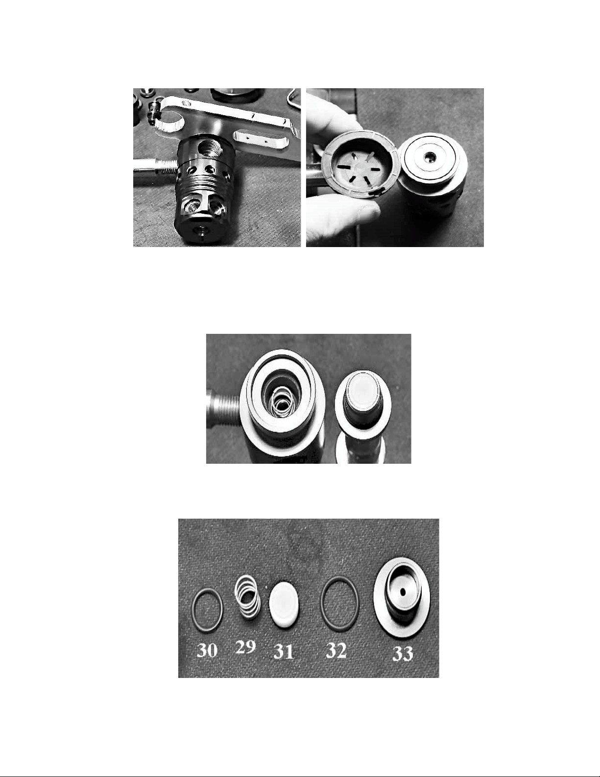
7. Using the Multitool or Pin Spanner, carefully remove the rubber End Cap (34) – Fig. 13. This exposes the
HP Seat Retainer (33) – Fig. 14.
Fig. 13 Fig. 14
8. Loosen the HP Seat Retainer with a 5mm hex wrench and remove it from the body, exposing the HP Seat
(31) – Fig. 15, (push out the HP seat with a blunt pick), remove Oring (32), Oring (30) and, Spring (29) – Fig.
16.
Fig. 15
9. Remove Oring 30 with a brass or nylon pick from its groove in the body of the regulator.
Fig. 16
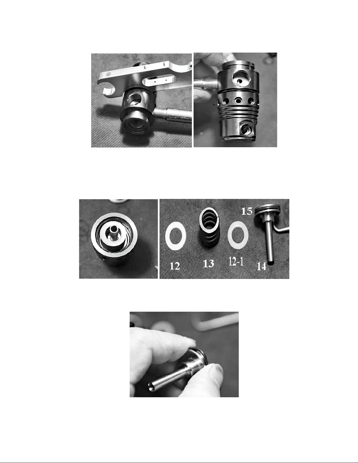
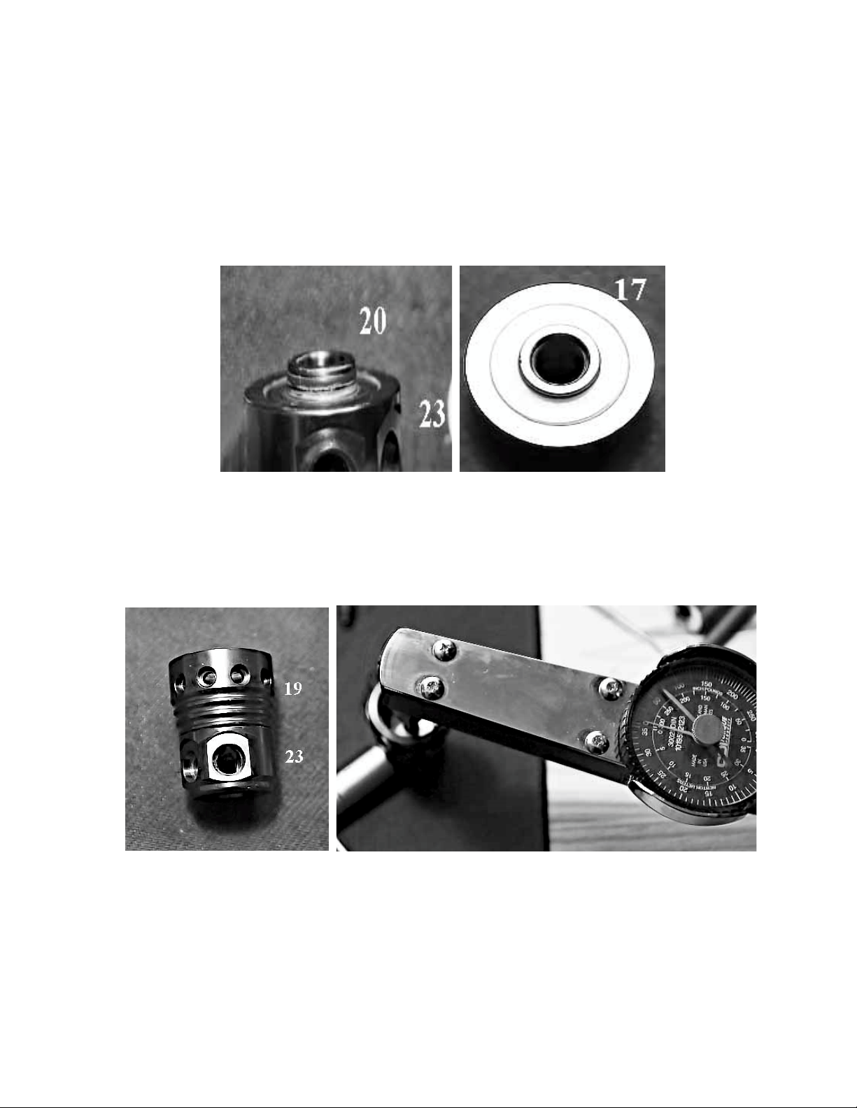
10. Using the universal wrench or a pin spanner with an appropriate pin, and the 1st stage handle secure –
Fig. 17, loosen the End Cap (19) so that a gap is visible – Fig. 18.
Fig. 17 Fig. 18
11. Holding the regulator vertical, with the end cap/turret on the bottom, unscrew the assembly from the
main body – Fig. 19. This allows access to the Piston (14), Washer (12), Spring (13), Washer (121), and Oring
(15) – Fig. 20.
Fig. 19 Fig. 20
12. Remove Oring 15, also using the pinch method to avoid scratching the piston sides – Fig. 21.
Fig. 21

13. Carefully remove the following components from the HP side of the regulator body. Washer (28), Oring
(27), and Teflon Washer (26) using the Piston Stem Bushing Assembly Tool – Fig.22. Turn the body over and
remove the other Oring (27) with a brass or nylon pick – Fig. 23.
Fig. 22 Fig. 23
14. Disassemble the turret by inserting a 1st stage handle into one of the low pressure ports. Using a 6 mm
hex wrench, unscrew the Nut (16) from the Port Swivel (23) Fig. 24.
Fig. 24
15. This allows access to the Washer (17). Remove the Washer. Pull the End Cap (19) from the Port Swivel
and remove the Washer (17) and Oring (20) from the Port Swivel – Fig. 25.
Fig. 25
This completes the disassembly of the 1st stage.

(3) The photographs below show the disassembled first stage – Fig. 26 and 1st stage service kit – Fig. 27. All
of the parts not in the service kit need to be washed, rinsed, and dried, as discussed previously.
Fig. 26
Disassembled 1st Stage
Fig. 27
1st Stage Service Kit
5. First Stage Assembly
(1) Before starting the assembly of the second stage, complete a thorough inspection of all parts to be re
used. Refer to the Overview Inspection section for details. At this time, open the service kit and lay out the
parts. Use the schematic to identify each part.
1. The first step in assembling the now cleaned 1st stage is to assemble the turret. Lubricate the Oring (20)
and install it on the port swivel (23) Fig. 28, along with Washer (17) Fig. 29.
Fig. 28 Fig. 29
2. Next, take the End Cap (19) and press it onto the Port Swivel (23) – Fig. 30. Install the other Washer (17),
as shown below. Install Nut (16) and torque this to 70 in lbs/81 kgf cm/8 Nm using a 6mm hex, and the 1st
stage handle installed in one of the open LP ports – Fig.31.
Fig. 30 Fig. 31

3. Set this assembly aside and install one of the Orings (27) into the groove on the regulator body that the
End Cap/Port Swivel assembly screws onto – Fig.32. Use the Piston Stem Bushing Assembly Tool and on the
narrower end place in the following order Washer (28), lubricated Oring (27), and Teflon Washer (26) – Fig.
33.
Fig. 32 Fig. 33
4. Next, lubricate Oring (15) Fig. 34 and install it on the Piston (14). Place the Washer (121) on the Piston,
followed by the Spring (13) Fig. 35, and the Washer (12) Fig. 36.
Fig. 34 Fig. 35 Fig. 36
5. Carefully slide the Piston Assembly into the End Cap/Port Swivel Assembly – Fig. 37. Using the previously
assembled Washer/Oring/Teflon Washer stack Fig. 38, insert the stack into the HP side of the regulator
Body (11), as shown on the schematic. Slightly twist the tool, and the stack will come off in the body.
Fig. 37 Fig. 38

6. Reverse the tool to hold the stack and protect the Piston end Fig. 39. Insert the Piston/End Cap/Port
Swivel assembly into the regulator and screw it on hand tight Fig. 40.
Fig. 39 Fig. 40
7. Install the 1st stage handle into a highpressure port Fig. 41. Use the MultiTool to tighten the End Cap/Port
Swivel assembly to the body. A piece of rubber may be used to lessen the chance of scratching the End Cap
Fig. 42. Tighten the connection so that no gap is visible, and the connection is secure. There is no torque
specification for this.
Fig. 41 Fig. 42
8. Set the assembly aside and install the Oring (30) in the HP side of the body, as shown using the blunt brass
or plastic pick Fig. 43. Install the Oring (32) onto the HP Seat Retainer and place the HP seat (31) into the
HP Seat Retainer. Orient the seat with the concave side towards the Piston and the flat side facing the HP
Seat Retainer Fig. 44.
Fig. 43 Fig. 44
This manual suits for next models
1
Table of contents
Other Dive Gear Express Diving Instrument manuals

Dive Gear Express
Dive Gear Express DGX Gears XTRA User manual

Dive Gear Express
Dive Gear Express DGX Gears D6 User manual

Dive Gear Express
Dive Gear Express DGX Gears FIRST User manual

Dive Gear Express
Dive Gear Express XTRA Second Stage User manual

Dive Gear Express
Dive Gear Express DGX Gears BCI Backup Regulator User manual


