Dive Gear Express DGX Gears XTRA User manual
DGX Gears XTRA
Second Stage Service Manual

Copyright © 2020 Dive Gear Express
All Rights Reserved.
Rev.6 Published 10/09/2020
Revision Date Changes
5c 8/17/2020 Initial publication
6 10/09/2020 Edited photos for clarity and added part numbers; reordered
photo numbering sequence Figs. 8-14 and Figs. 18-41; Tool
List rearranged, added Scuba Tools link; renumbered
3. Preliminary Testing; edited text: disassembly items (1),
(2) and (3), 2., 6., 7., 8., assembly items (2), 1., 4., combined
6. and .7, 14.; updated schematic diagram
6a 10/14/2020 Replaced photos for Figs. 18 and 24

1. Overview
(1) The availability of subassemblies and components, repair parts, specialized tools, and maintenance
manuals does not imply qualification to assemble and/or service scuba equipment. Improper service
of dive equipment can lead to severe injury or death. Dive Gear Express recommends that non-qualified
individuals seek professional training/mentoring before attempting repairs or servicing on any diving
equipment.
Failure to follow the procedures outlined herein may result in injury or death!
(2) In the following pages will be found the disassembly, assembly, tuning and troubleshooting steps
for these components. Photos are used throughout to illustrate the procedures.
Please pay special attention to all Caution Notes!
(3) Whenever an item of extra importance needs to be observed, a “Caution Note:” will appear, followed
by the required information. See below.
Caution Note: This must be read and followed!
(4) Included in this manual is a list of recommended/required tools for each disassembly, assembly,
and testing section. They are identified in each section where they are used.
(5) A schematic diagram is located at the rear of this manual. The diagram contains the detailed parts
lists. The diagram also includes the torque specifications for parts where required.
(6) A general troubleshooting guide with space for notes is also included for those using a printed
version. Those who prefer an electronic version should keep detailed notes in an accessible location
for their own observations and service tips, as well as a record of service.
(7) Throughout the text, parts are referenced using the item number on the schematic to facilitate
locating each individual component.
(8) Photographs of the parts kits are shown to illustrate that each component is individually bagged.
Parts should not be taken out of their packaging until the actual assembly stage is reached, and the
user is ready to lubricate, where necessary, and install them.
(9) Ensure the service area is free of any environmental concerns that may cause problems during the
servicing of your regulators. The area must be clean and organized. The use of nitrile gloves is highly
recommended for the final rinsing and assembly stages. This will minimize the risk of skin oils
contaminating the internal components of the regulator.
(10) Ensure that all required servicing/testing air supplies are available and at the proper test pressures
if not using a regulated supply from a single source. This includes the use of cylinders of compressed
breathing air from an OCA grade source if you wish to maintain the oxygen-clean status of the unit.
Caution Note: Only use air from a breathing air source!

Cleaning and Rinsing - General Considerations
(11) Cleaning and rinsing of the components should be done using clean, fresh water. If available,
distilled water is recommended to maintain oxygen cleanliness.
(12) Only use degreasers that leave no organic residue (e.g. Simple Green Free & Clear, Blue Gold
Cleaner, or any clear liquid dish soap that does not contain scents or dyes).
(13) To deal with corrosion, use a 50/50 vinegar/water solution and nylon brushes.
(14) Allow parts to air dry without the use of cloths that may leave fibers. For regulators that are going
to be used with oxygen percentages above 40%, a UV light is strongly recommended to check for
organic contamination.
(15) Once all service procedures have been completed and bench testing done, in-water testing in a
confined environment such as a swimming pool is recommended to confirm proper function before
taking the regulator on an actual dive.
Cleaning of Regulator Parts
(16) Cleaning of the parts that are going to be reused is one of the most critical steps in servicing the
regulator. As was stated earlier, use the proper solutions for the job at hand. Vinegar and water are not
as useful for removing lubricating grease as one of the detergents that were noted. By the same token,
those detergents are not as efficient as the vinegar/water mix in dealing with corrosive buildup.
(17) Therefore, where you have a buildup of corrosion, you may also have lubricant on the surface of
the part. Before dealing with the corrosion, use hot soapy water and a soft brush to remove the
lubricant. Then use the acidic solution to deal with the corrosion.
(18) Once the corrosion has been dealt with, wash the parts using a fresh soap and water solution while
wearing nitrile gloves to reduce the risk of contaminating the parts with skin oils. Rinse the parts with
clean running water, distilled is preferred, that can drain freely. A plastic pasta colander is excellent for
this. For very small parts, a mesh strainer for sink drains works well. Often sold as a set, they are
inexpensive and can be used for many types of regulator components. See the photographs of each in
the tool section.
(19) After washing and rinsing the regulator parts, allow them to air dry. Using a drying rack will aid in
this, as well as having the air in the room circulating. Do not lay the parts on a paper or cloth towel.
Doing so runs the risk of having fibers stick to them that will cause issues with sealing. In addition to
this, fibers can be a hazard when using the regulator with high oxygen content mixes.
(20) Once the parts have dried completely, lay them out in order of assembly on the pad used on the
work surface. A rubber or silicone mat of suitable size that is clean and free of contaminants works
well for this. You can also use small clean containers to keep the parts organized. Once the parts have
been cleaned and dried, they need to be inspected before starting the assembly process.
Inspection After Cleaning
(21) Before assembling the regulator, it is necessary to inspect all the cleaned components. Using the
magnifying glass, ensure all parts are clean and contaminate-free, and check the components for
damage that may have been hidden by corrosion or lubricant. Look for scratches that may affect the
sealing of the regulator. In a darkened room, use the UV light to look for organic material. If any are
present, re-clean the part! This is critical for use with oxygen percentages above 50%!
(22) Another way to check for residual lubricants is to fill a tray with clean, fresh water deep enough to
cover the parts by an inch or so. Lay the components in and circulate the water. Allow the pieces to
soak for several minutes. Once it has settled, look for a rainbow sheen on the surface of the water. Any
residual lubricants will float and form a “slick” on the surface. If one is present, the parts must be
cleaned again.
(23) Now that all parts have been cleaned and checked, the assembly can begin. Make sure all old parts
that are to be replaced have been discarded or segregated. Remove the new parts from the main
service kit bag and lay them out in the order they will be used. Do not take the new parts out of the
individual bags yet!
Caution Note: Removing parts from their individual bags, before they are to be
used, runs the risk of mixing them up. Some O-rings are very close in size but are
not interchangeable! Keep the parts in the bags until you need them.
(24) As with the parts that have been cleaned, it is a good idea to inspect the new parts as well. Inspect
the HP seat to ensure it is free of any defects. Check all the O-rings and inspect them as you use them
for nicks or other concerns. Inspect the washers to ensure they are free of excess burrs or other issues
that could affect their function. It is also a good idea to use the parts list on the schematic to ensure
that all the new parts that are needed are present and accounted for in their required quantities.
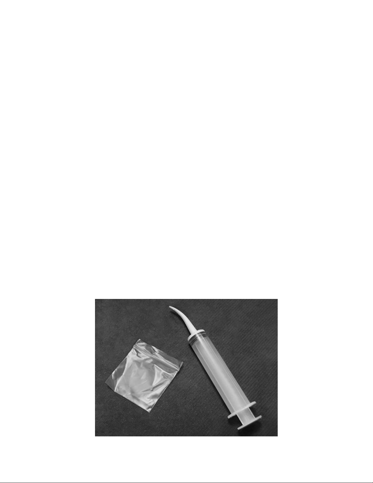
(25) Lubrication can be overdone.Doing so runs the risk of trapping excess dirt or debris on the parts.
One way of reducing the risk of overdoing it is to use the lube-in-a-bag method – Fig. 1
Fig. 1
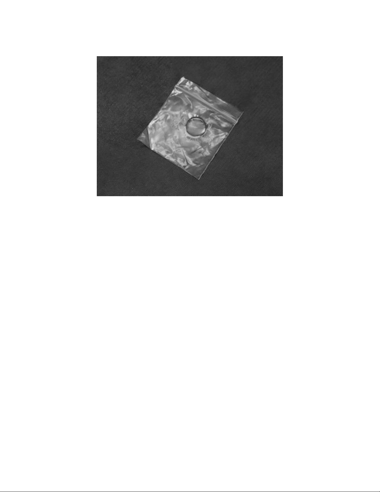
This involves using a small clean plastic bag containing a small amount of lubricant. The O-ring is
inserted into the bag, worked around to evenly coat with lube while squeezing off excess, then taken
out of the bag and used in its location – Fig. 2.
Fig. 2.
(26) Another way is to apply a small amount of lubricant to the gloved index finger and massage the O-
ring between the thumb and index finger. Either way works, but the bag method tends to give better
distribution results and uses less lubricant.
(27) Under most circumstances, a lubricant should be used very sparingly or not at all. In nearly all
scuba applications, if you can see the lubricant, too much has been applied. Before using any lubricant,
any existing lubrication should be removed before new is applied. In dynamic applications, it is used to
reduce excessive wear. Static O-rings do not generally require the use of lubricant.
(28) Where parts are not necessary to be lubricated, it is good practice to avoid getting any lubricant
on them, especially when the regulator is used with high oxygen content mixes. It also helps to keep
those parts clean and free of debris that will cling to the lubricant.
(29) Maintaining oxygen clean conditions for second stages is technically not mandatory. The second
stage is a low pressure device operating at 135 psi. Regardless, best practice is to maintain oxygen
clean conditions along with the exclusive use of oxygen compatible lubricants when servicing the
regulator.

2. Tool List
(1) The tool list for the second stage is not as extensive as that for the first stage. They are still divided
into Required and Recommended. Required tools are necessary for servicing the regulator.
Recommended tools make servicing easier or more efficient, as well as lessen the chance of damage.
Required Tools – Fig. 3
1. 2 Adjustable (or 11/16 and proper size for hose attachment) thin-jawed wrenches
2. Second Stage In-Line Adjusting Tool with slotted orifice selected
3. 3/16 hex wrench
4. Straight blunt and pointed brass O-ring picks
5. Tribolube 71
6. Wooden or plastic dowels, 1/8 – 3/16 diameter
7. Soft bristle cleaning brushes (nylon)
Fig. 3

Recommended Tools - Figs. 4 and 5
1. Magnehelic gauge with 0-3 inches scale - Fig.4, or a waterproof ruler/scale
2. Soft rubber pad
3. Magnifying glass
4. Flashlight
5. UV light
Fig. 4 Fig. 5
(2) The In-Line Adjusting Tool with IP Gauge, IP Gauge and Brass O-Ring Pick Set can be found at Dive
Gear Express using the link below.
https://www.divegearexpress.com/tools/scuba-tools
(3) Tools may also be purchased from Scuba Tools at the link below.
www.scubatools.com

3. Preliminary Testing
(1) Preliminary testing of the regulator is necessary to identify any issues with the first and second
stages and verify the overall regulator function. This testing will include:
1. Visual inspection of the first and second stages
2. Inspection of the hoses
3. Intermediate Pressure (IP) check
4. Cracking pressure and second stage negative pressure test
Visual inspection is done to identify issues that could affect servicing and to ensure that pressurizing
the system will not compromise the safety of the service technician.
The technician will check all connections to make sure they are secure.
The technician will check that on the first stage, there are no extruded O-rings, and hoses are tight.
The technician will check there are no defects to the SPG.
The technician will ensure that the DIN assembly is secure, and the O-ring is intact and able to form a
seal.
The technician will inspect the filter for signs of discoloration.
Detailed inspection of hoses is done to ensure it is safe to pressurize the regulator set.
The technician will check all hoses, looking for evidence of possible failure.
The technician will check all hose connection crimps. Defects must be taken care of before
pressurizing the system! Replacement of any suspect hoses is recommended.
Caution Note: Defects in hoses require replacement before pressurizing the
regulator! Failure to do so may result in serious injury or death!
(2) The technician will check the SPG for any signs of cracking of the face, water intrusion, and
corrosion around the SPG to the hose connection. If using a console or boot, it is necessary to remove
the SPG from the rubber boot. Once this is done, the HP spool should be inspected and, if necessary,
replaced.
(3) The Intermediate Pressure (IP) of the system should be tested only after the preceding checks have
been done to ensure technician safety. Checking of intermediate pressure is done by attaching an IP
gauge to the low pressure (LP) inflator hose. The system is then pressurized while partially depressing
the purge button on one of the second stages. Depressing the purge button slightly on the second stage
is done to prevent further damage to the system by providing a relief valve should the IP rise rapidly to
unsafe levels. Once the system has been pressurized, the purge is released, and the IP checked.

Caution Note: If the second stage is leaking even slightly, IP will be affected. If
it is leaking, turn the adjustment knob to stop the flow or use a second stage that
is not leaking when paired with the first stage. It is a clear indication that the
second stage requires rebuilding if turning the adjustment knob does not stop
the flow.
(4) The standard operating range for the system is with an IP of 135 PSI. Ideally, the system is operating
at 135 PSI +/- 5 PSI and show no signs of “creep” or instability at 3000 PSI.
Caution Note: “Creep” will show as the IP steadily increasing while the regulator
is not in use. Normally the IP will drop 5-10 PSI during a breath or purge and then
return to its setting. It should not return to the setting and keep increasing. This
would indicate a problem with the High Pressure Seat, Piston, or sealing O-rings.
(5) If the system shows no sign of creep or IP instability, it is generally not necessary to rebuild the first
stage, with some exceptions.
Caution Note: If the unit shows signs of internal corrosion or the filter shows
evidence of contamination, the unit must be rebuilt, regardless of the IP.
(6) The regulator will require rebuilding if small bubbles are leaking from between the turret retainer
and main body, from under the rubber cap, or out of the high-pressure seat retainer. Knowledge of
flooding of the first stage will also require the unit to be rebuilt. Freshwater contains dissolved minerals
and other materials that, due to internal corrosion over time, may cause the regulator to malfunction.
(7) After the IP has been checked, hoses and regulator body inspected, and SPG evaluated, the second
stage inspection can take place. It is necessary to perform an inspection of the first stage and check
the intermediate pressure. Intermediate pressure has a direct bearing on the performance of the
second stage. Incorrect IP can give false indications as to the level of service required on the second
stage.
Caution Note: It may be necessary to service the second stage when the first
stage does not require service. All inspection steps and evaluations should be
done to ensure proper operation of the entire assembly.

4. Second Stage Evaluation
(1) The negative pressure test verifies the seals of the main and exhaust diaphragms, and verifies case
integrity. With the supply pressure off, and attached to a cylinder, attempt a normal breath from the
second stage. You should be unable to draw any air. If a flow is obtained, remove the second from the
hose and try to draw air while sealing the hose inlet with your thumb. If a flow is still present, the primary
and exhaust diaphragms need to be checked for damage. Salt accumulation, sand, and defects in the
case will also allow airflow when the air inlet is covered. Carefully check all of these.
(2) Cracking pressure testing is most accurately done with the use of a magnehelic gauge. A container
of water can be used by measuring the depth to which a stage can be submerged face-down parallel
to the water. This gives an indication at which level of effort the second stage will open. The normal
range for the adjustable second stage is 1.0 to 2.2 inches of water. Less pressure may be desired by
the diver, but the initial factory setting of 1.1 should be used. This permits a break-in period for the LP
seat. It is normal to see this initial setting drop as the LP seat takes a set.
(3) The case should be inspected for signs of damage. Scratches, gouges, missing parts, damaged
exhaust ports, or a loose faceplate that will not tighten may be an indication of a damaged case.
(4) Use a negative pressure test, test the purge button, and look for defects. Check the lever and
breathing effort knob. Do they move freely and with no indication of stiffness? Do they feel like there is
sand or grit in them?
(5) A problem with case integrity should be dealt with before starting the rebuild. A defective case will
compromise final testing and pose a safety hazard to the user.
Caution Note: A damaged case, purge cover, or diaphragm cannot be repaired.
They must be replaced.
(6) Having completed the initial evaluation and determined service is necessary, the rebuild of the
regulator can take place.

5. Second Stage Disassembly
(1) Ensure the system is depressurized. The use of small, clean containers to hold parts is
recommended.
(2) In the following steps, the part numbers from the schematic will be used with their description. The
numbers on the photos also correspond with the parts list on the schematic. Items in the service kits
are identified in the same way. Have the schematic in front of you while following the instructions. Be
sure to keep all old parts organized and separate from new ones in the service kit. The old washers and
O-rings marked with an asterisk (*) will be replaced with new ones from the service kit and the
remaining parts will be cleaned and reused.
1. Remove the Second Stage from the hose. Unscrew the Case Cover (4-1) from the Case (11) and
remove the Cover (03), Diaphragm Cover (04), and the Diaphragm (06*) and Diaphragm Disc (05*)
assembly - Fig. 6. This reveals the Valve Spindle Assembly in the Case - Fig. 7.
Fig. 6 Fig. 7
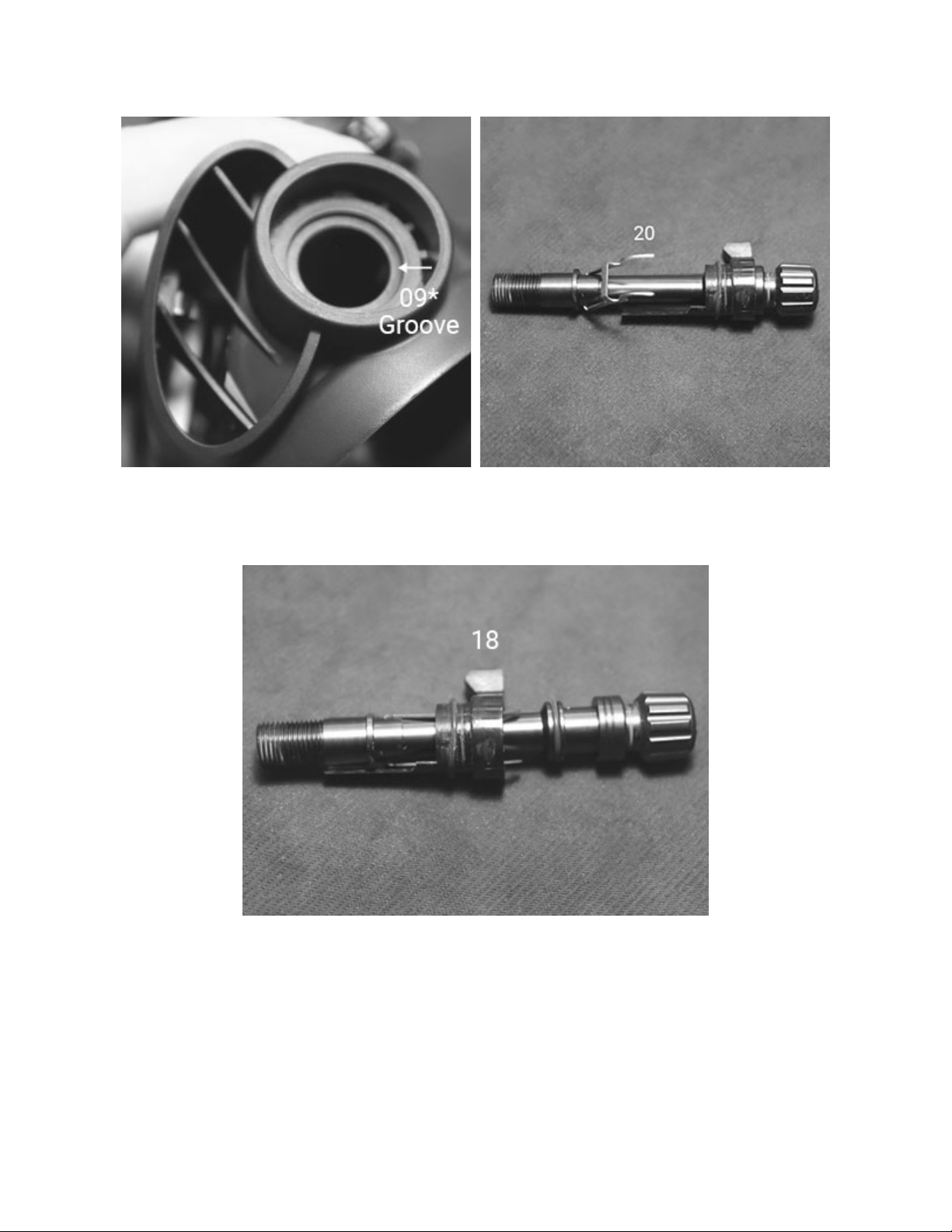
2. Remove the Retaining Nut (08) and the O-ring (09*) from its groove in the Case – Fig 8. Holding the
Lever (20) down, slide/pull the Valve Spindle Assembly out of the case as one unit - Fig. 9.
Fig. 8 Fig. 9
3. Slide the Venturi Lever (18) off the spindle while holding down the Lever – Fig 10. After sliding the
Venturi Lever off, carefully allow the Lever to come up slowly.
Fig. 10

4. With the lever off, using the brass pick blunt end or another suitable tool, press the Spring Pin (21*)
out of the Valve Spindle (19). Note that this may require some force to remove. Secure the spindle as
needed. This will allow the Adjusting Screw (30) to be removed. Remove the Rubber Cap (35) from the
Adjusting Screw. Using the 3/16 hex wrench, unscrew the Adjusting Spring (34) from the Adjusting
Screw – Fig. 11.
Fig. 11
5. Holding the lever upright, use the 1/8 inch plastic or wooden dowel to push the assembly consisting
of the LP Seat (24), Shuttle Valve (25), O-rings (26*), Spring (27), and Counter Balance Cylinder (28) out
of the Spindle. You may hear a slight click as you do this when the LP Seat end passes the Lever - Fig.
12. An alternative method is to carefully remove the lever by lifting one leg out of the hole and rotating
the spindle to allow the other side to come out. DO NOT BEND THE LEGS OF THE LEVER TO DO THIS!
Fig. 12
6. Once you have removed the assembly from the Spindle, use the slotted end of the In-Line Adjusting
Tool to remove the Orifice (15) from the Spindle. The photo below shows all the parts of the Spindle
Assembly – Fig. 13.
Fig. 13
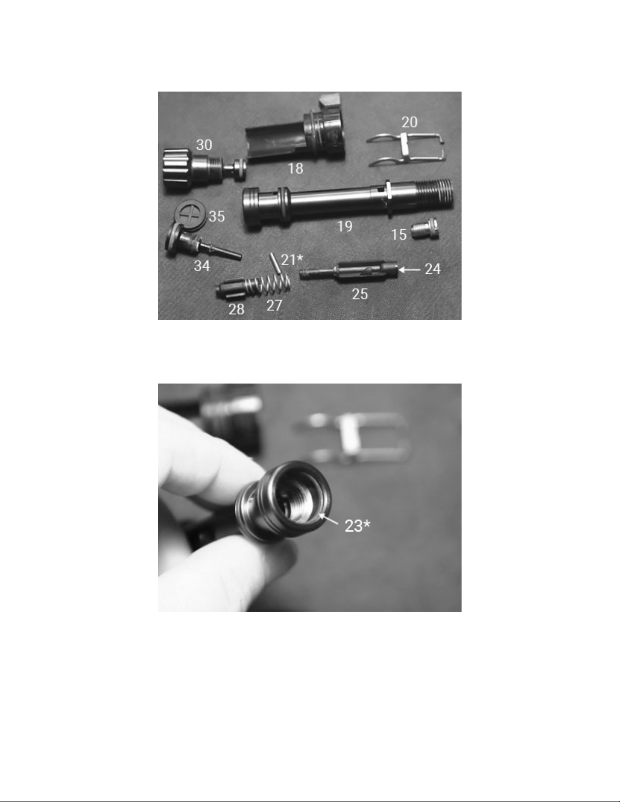
7. O-ring (23*) is seated in a groove on the inside of the Spindle. Using a brass pick, carefully remove
the O-ring from the Spindle – Fig. 14. Remove the LP Seat from the Shuttle Valve.
Fig. 14

8. Using the pinch method or a brass/plastic pick, remove all the O-rings from the Venturi Lever, Orifice,
Valve Spindle, Shuttle Valve, Adjusting Screw, and Adjusting Spring - Fig. 15. Confirm that all are
accounted for and segregate them with the other replaceable parts.
Fig. 15
9. Carefully cut the zip tie on the Mouthpiece (14) and remove it from the case. Using a blunt pick or
wooden dowel, press the small tab slightly on the adjustment/lever side of the case in the exhaust
port to remove the Cover Exhaust Valve (13) - Fig. 16. Be careful not to snap the tab off! Gently
remove the cover as you press the tab. Do not try to pry it off without pressing the tab! The Exhaust
Valve (12*) can be removed by pulling it out of the hole intact or by cutting the stem inside the case
and pulling it out. Replacing the valve is optional - Fig. 17.
Fig. 16 Fig. 17
This completes the disassembly of the XTRA Second Stage.
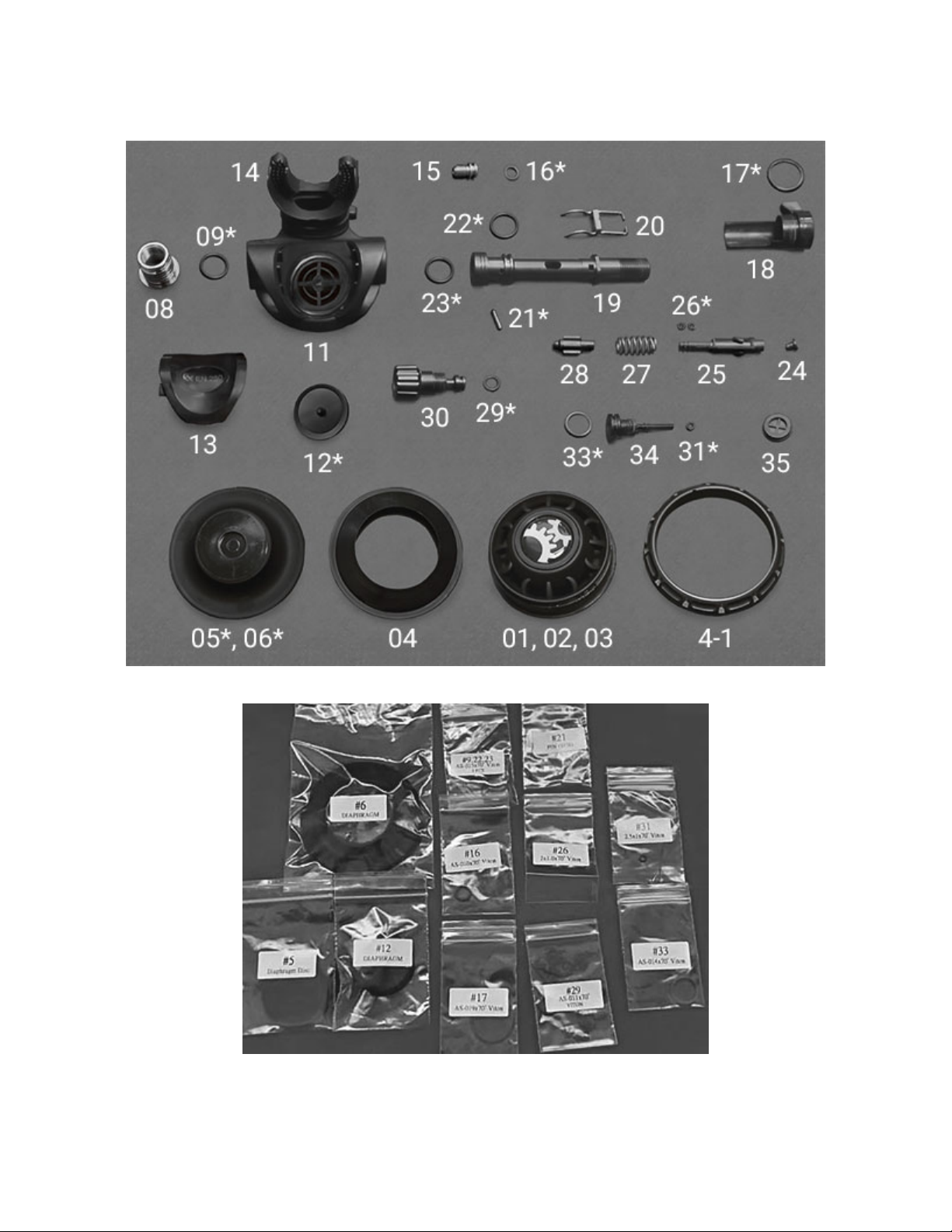
(3) The photographs below show the disassembled second stage – Fig. 18 and Second Stage Service
Parts Kit – Fig. 19. All the parts not in the service kit need to be washed, rinsed and dried, as discussed
previously. O-rings and washers that will be replaced with new from the service kit should be discarded.
Fig. 18
Fig. 19
6. Second Stage Assembly
(1) Before starting the assembly of the second stage, complete a thorough inspection of all parts to be
reused. Refer to the Overview Inspection section for details. At this time, open the service kit and lay
out the parts. Use the schematic to identify each part.
Caution Note: Only use enough lubricant to lightly coat the O-rings and ensure no
debris is trapped on them.
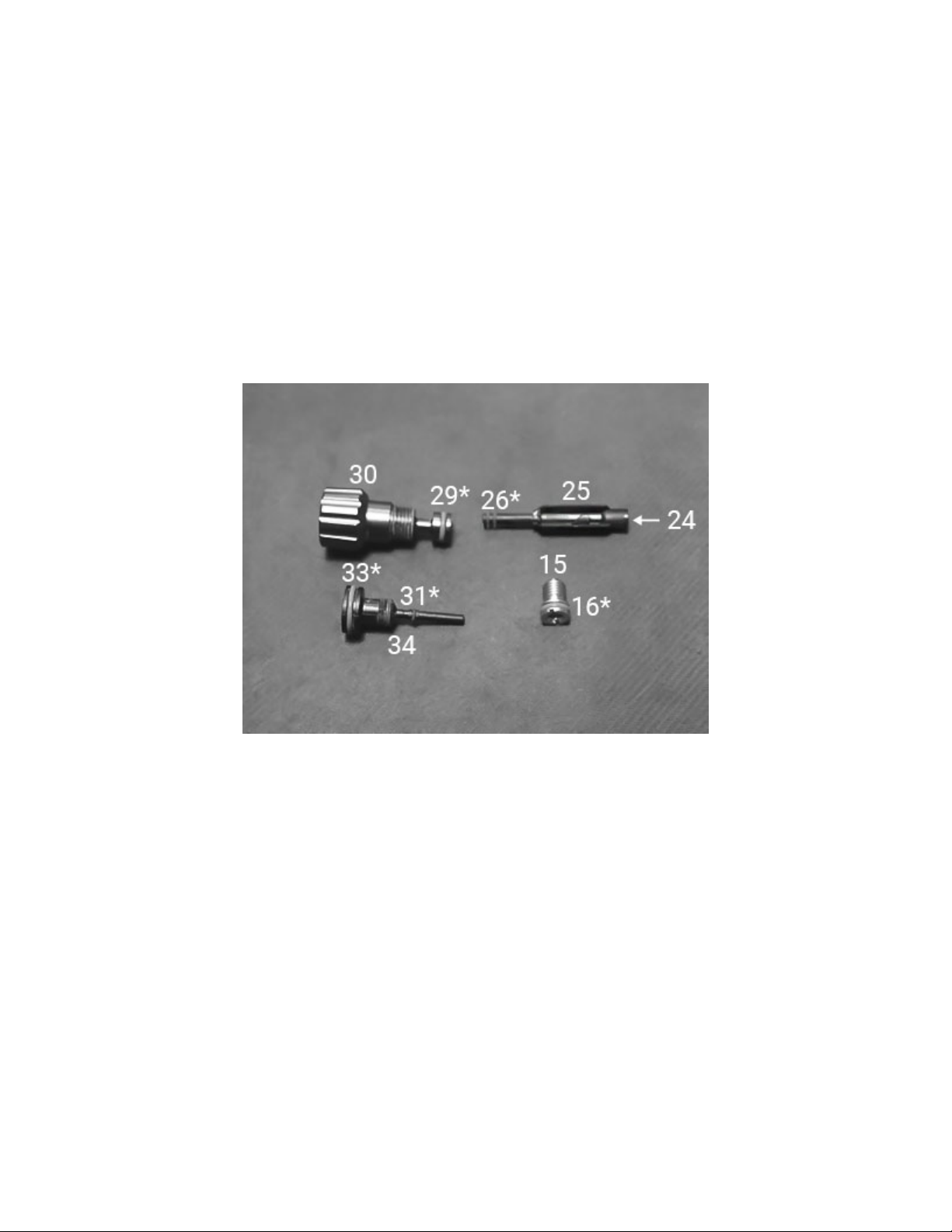
1. The first step in assembling the now cleaned second stage is to install O-rings on the individual parts
of the Valve Spindle Assembly. Lubricate the O-rings (31* and 33*) and install them on the Adjusting
Spring (34). Place the O-ring (16*) on the Orifice (15). Install the two O-rings (26*) on the Shuttle Valve
(25). Install the O-ring (29*) on the Adjusting Screw (30). At this time, the LP Seat (24) can be placed
into the end of the Shuttle Valve - Fig. 20.
Fig. 20
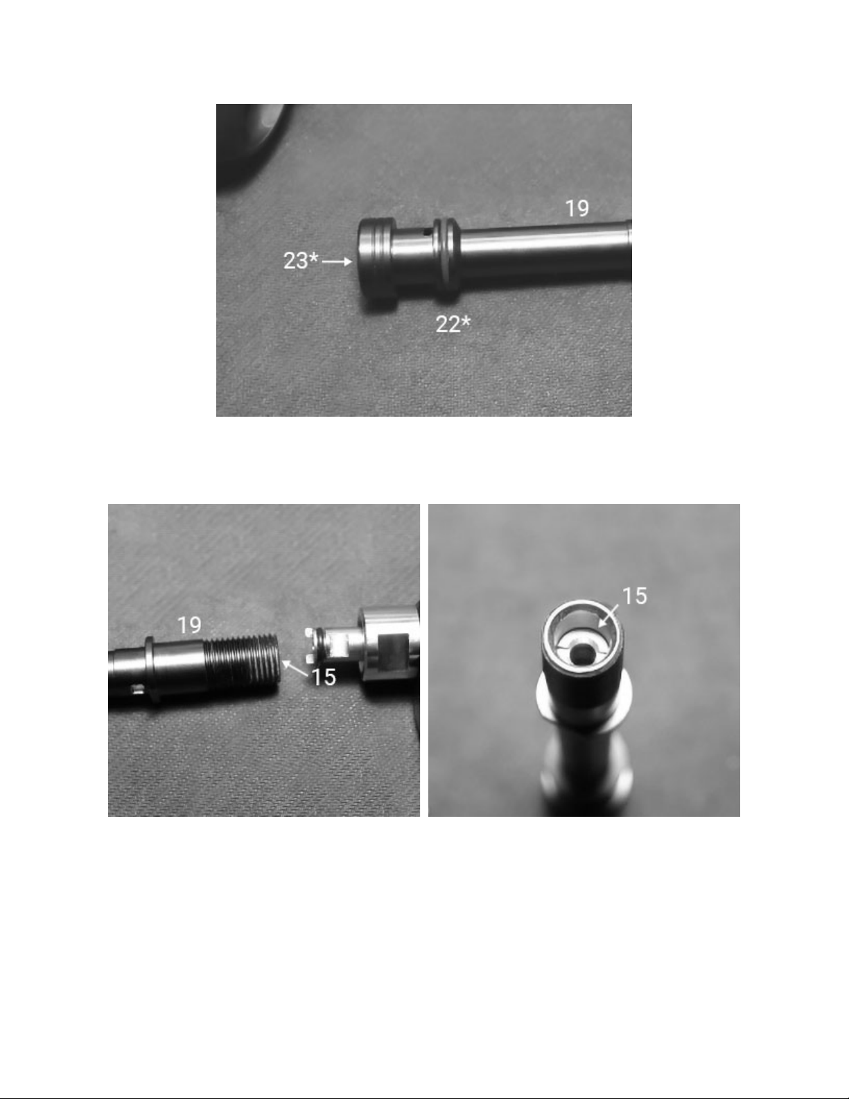
2. Lubricate and install the O-ring (22*) on the Valve Spindle (19). Install the O-ring (23*) in the interior
groove of the Spindle on the same side - Fig. 21.
Fig. 21
3. Using the In-Line Tool, insert the Orifice (15) into the threaded end of the Spindle – Fig. 22, and when
the threads engage, turn it inward 3-4 turns. Actual adjusting of the Orifice will be done later – Fig. 23.
Fig. 22 Fig. 23
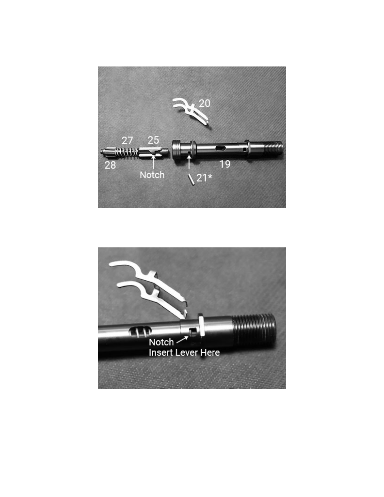
4. Assemble the Shuttle Valve, Spring (27), and Counter Balance Cylinder (28). With the assembly
oriented, as shown in Fig. 24, insert it into the Spindle. Pay special attention to the position of the notch
on the Shuttle Valve. This is where the Lever (20) engages the Shuttle Valve. It must be oriented in this
manner. Also note the position of the hole for the Spring Pin (21*) – Fig. 24.
Fig. 24
5. Carefully insert the assembly the rest of the way into the spindle. It is critical to maintain this
orientation. Slide it in until the notch is clearly visible in the small square window – Fig. 25.
Fig. 25
Other manuals for DGX Gears XTRA
2
Table of contents
Other Dive Gear Express Diving Instrument manuals

Dive Gear Express
Dive Gear Express DGX Gears D6 User manual

Dive Gear Express
Dive Gear Express DGX Gears BCI Backup Regulator User manual

Dive Gear Express
Dive Gear Express DGX Xtra First Stage User manual

Dive Gear Express
Dive Gear Express DGX Gears FIRST User manual

Dive Gear Express
Dive Gear Express XTRA Second Stage User manual


