Dive Gear Express XTRA Second Stage User manual
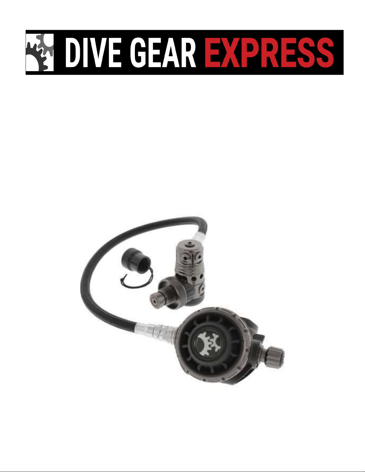
DGX Gears XTRA Regulator
Service Manual
DGX Xtra Second Stage

Copyright © 2020 Dive Gear Express
Author/Photographer – UDM Consulting
All rights reserved.
Rev.5c Published 8/17/2020

1.Overview
(1) The availability of subassemblies and components, repair parts, specialized tools, and maintenance
manualsdoesnotimplyqualificationtoassembleand/orservicescubaequipment.Improperserviceofdive
equipmentcanleadtosevereinjuryordeath.DiveGearExpressrecommendsthatnonqualifiedindividuals
seekprofessionaltraining/mentoringbeforeattemptingrepairsorservicingonanydivingequipment
Failuretofollowtheproceduresoutlinedhereinmayresultininjuryordeath!
(2)Inthefollowingpageswillbefound,thedisassembly,assembly,tuning,andtroubleshootingstepsfor
thesecomponents.Photosareusedthroughouttoillustratetheprocedures.
Pleasepayspecialattentiontoallcautionnotes!
(3)Wheneveranitemofextraimportanceneedstobeobserved,a“CautionNote:”willappear,followedby
therequiredinformation.Seebelow.
CautionNote:Thismustbereadandfollowed!
(4) Included in this manual is a list of recommended/required tools for each disassembly, assembly, and
testingsection.Theyareidentifiedineachsectionwheretheyareused.
(5) Schematics are located inthe rear of this manual. The drawings containthe detailed parts lists. The
drawingsalsoincludethetorquespecificationsforpartswhererequired.
(6)Ageneraltroubleshootingguidewithspacefornotesisalsoincludedforthoseusingaprintedversion.
Thosewhopreferanelectronicversionshouldkeepdetailednotesinanaccessiblelocationfortheirown
observationsandservicetips,aswellasarecordofservice.
(7)Throughoutthetext,partsarereferencedusingtheitemnumberontheschematictofacilitatelocating
eachindividualcomponent
(8)Photographsofthepartskitsareshowntoillustratethateachcomponentisindividuallybagged.Parts
shouldnotbetakenoutoftheirpackaginguntiltheactualassemblystageisreached,andtheuserisready
tolubricate,wherenecessary,andinstallthem.
(9) Ensure the service area is free of any environmental concerns that may cause problems during the
servicing of your regulators. The area must be clean and organized. The use of nitrile gloves is highly
recommendedforthefinalrinsingandassemblystages.Thiswillminimizetheriskofskinoils,contaminating
theinternalcomponentsoftheregulator.
(10)Ensurethatallrequiredservicing/testingairsuppliesareavailableandatthepropertestpressures,if
not using a regulated supply from a single source. This would include the use of cylinders of compressed
breathing air from an OCA grade source if you wish to maintain the oxygenclean status of the unit.
CautionNote:Onlyuseairfromabreathingairsource!

CleaningandRinsingGeneralConsiderations
(11)Cleaningandrinsingofthecomponentsshouldbedoneusingclean,freshwater.Ifavailable,distilled
waterisrecommendedtomaintainoxygencleanliness.
(12) Only use degreasers that leave no organic residue (clear Simple Green, dyefree Dawn dishwashing
liquid,orBlueGoldCleanerasexamples).
(13)Todealwithcorrosion,usea50/50vinegarwatersolutionandnylonbrushes.
(14)Allowpartstoairdrywithouttheuseofclothsthatmayleavefibers.Forregulatorsthataregoingtobe
used with Oxygen percentages above 40%, a UV light is strongly recommended to check for organic
contamination.
(15)Onceallserviceprocedureshavebeencompletedandbenchtestingdone,inwatertestinginaconfined
environment such as a swimming pool is recommended to confirm proper function before taking the
regulatoronanactualdive.
CleaningofRegulatorParts
(16)CleaningCleaningofthepartsthataregoingtobereusedisoneofthemostcriticalstepsinservicing
theregulator.Aswasstatedearlier,usethepropersolutionsforthejobathand.Vinegarandwaterarenot
asusefulforremovinglubricatinggreaseasoneofthedetergentsthatwerenoted.Bythesametoken,
thosedetergentsarenotasefficientasthevinegar/watermixindealingwithcorrosivebuildup.
(17)Therefore,whereyouhaveabuildupofcorrosion,youmayalsohavelubricantonthesurfaceofthe
part.Beforedealingwiththecorrosion,usehotsoapywaterandasoftbrushtoremovethelubricant.Then
usetheacidicsolutiontodealwiththecorrosion.
(18)Oncethecorrosionhasbeendealtwith,washthepartsusingafreshsoapandwatersolutionwhile
wearingnitrileglovestoreducetheriskofcontaminatingthepartswithskinoils.Rinsethepartswithclean
runningwater,distilledispreferred,thatisallowedtodrainfreely.Aplasticpastacolanderavailableatany
storeisexcellentforthis.Forverysmallparts,ameshstrainerforsinkdrainsworkswell.Oftensoldasa
set,theyareinexpensiveandcanbeusedformanytypesofregulatorcomponents.Seethephotographsof
eachinthetoolsection.
(19)Afterwashingandrinsingtheregulatorparts,allowthemtoairdry.Usingadryingrackwillaidinthis,
aswellashavingtheairintheroomcirculating.Donotlaythepartsonapaperorclothtowel.Doingsoruns
theriskofhavingfiberssticktothemthatwillcauseissueswithsealing.Inadditiontothis,fiberscanbea
hazardwhenusingtheregulatorwithhighoxygencontentmixes.
(20)Oncethepartshavedriedcompletely,laythemoutinorderofassemblyonthepadusedonthework
surface.Makingsurethatithasbeencleanedandisfreeofcontaminants.Arubberorsiliconematofsuitable
sizeworkswellforthis.Youcanalsousesmallcleancontainerstokeepthepartsorganized.Oncetheparts
have beencleanedand dried,theyneed to beinspected beforestarting theassemblyprocess.Thisis to
ensure that no damage or defects exist that were hidden by corrosion, residual lubrication, or other
contaminantsthathavenowbeenremoved.

InspectionAfterCleaning
(21)Beforeassemblingtheregulator,itisnecessaryto inspectallofthecleaned components. Usingthe
magnifyingglass,checkallthecomponentsfordamagethatmayhavebeenhiddenbycorrosionorlubricant.
Lookforscratchesthatmayaffectthesealingoftheregulator.Inadarkenedroom,usetheUVlighttolook
fororganicmaterial.Itwillshowupasglowinglinesorfragments.Ifanyarepresent,thepartneedstobere
cleanedanddried!Thisiscriticalforusewithoxygenpercentagesabove50%!
(22)Anotherwaytocheckforresiduallubricantsistofillatraywithclean,fresh,waterdeepenoughtocover
thepartsbyaninchorso.Laythecomponentsinthewaterandcirculatethewateraroundthem.Allowthe
piecestosoakforseveralminutesandthewatertosettle.Onceithassettled,lookforarainbowsheenon
thesurfaceofthewater.Anyresiduallubricantswillfloatandforma“slick”onthesurface.Ifoneispresent,
thepartsmustbecleanedagain.
(23)Nowthatallpartshavebeencleanedandchecked,theassemblycanbegin.Makesurealloldpartsthat
aretobereplacedhavebeendiscardedorsegregated.Removethenewpartsfromtheservicekitbagand
laythemoutintheordertheywillbeused.Donottakethenewpartsoutofthebagsyet!
CautionNote:
Removingpartsfromtheirindividualbags,beforetheyaretobeused,runstheriskof
mixingthemup.Someoringsareverycloseinsizebutarenotinterchangeable!Keep
thepartsinthebagsuntilyouactuallyneedthem.
(24)Aswiththepartsthathavebeencleaned,itisagoodideatoinspectthenewpartsaswell.Especially
theHPseat.Makesureitisfreeofanydefects.Checkalloftheoringsandinspectthemasyouusethemfor
nicksorotherconcerns.Inspectthewasherstoensuretheyarefreeofexcessburrsorotherconcernsthat
couldaffecttheirfunction.Itisalsoagoodideatousethepartslistontheschematictoensurethatallofthe
newpartsthatareneededarepresentandaccountedforintheirrequiredquantities.
(25)LubricationofOrings;Lubricationcanbeoverdone.Doingsorunstheriskoftrappingexcessdirtor
debrisontheparts.Onewayofreducingtheriskofoverdoingitistousethelubeinabagmethod.This
involvesusingasmallcleanplasticbagandputtingasmallamountoflubeinit.Thentheoringisinserted
intothebag,workedaround,excesssqueezedoff,andtakenoutofthebag,andusedinitslocation.
Fig.1Fig.2

(26)AnotherwayistoapplyasmallamountofTribolubetotheglovedindexfingerandmassagetheoring
betweenthethumbandindexfinger.Eitherwayworks,butthebagmethodtendstogivebetterdistribution
resultsanduseslesslubricant.
(27)Undermostcircumstances,alubricantisusedcorrectlyverysparinglyornotatall.Innearlyallscuba
applications, ifyoucan see thelubricant, you’ve usedtoomuch. Before using any lubricant, any existing
lubricationshouldberemovedbeforenewisapplied.Indynamicapplications,itisusedtoreduceexcessive
wear.Staticoringsdonotgenerallyrequiretheuseoflubricant.
(28)Wherepartsarenotnecessarytobelubricated,itisgoodpracticetoavoidgettinganylubricantonthem.
PrimarilywhentheregulatorisusedwithhighO2contentmixes.Italsohelpstokeepthosepartscleanand
freeofdebristhatwillclingtothelubricant.
(29)Maintainingoxygencleanconditionsfor2ndstagesistechnicallynotmandatory.The2ndstageisalow
pressuredeviceoperatingat135psi.Regardless,bestpracticeistomaintainoxygencleanconditionsalong
withtheexclusiveuseofoxygencompatiblelubricantswhenservicingtheregulator.
Thenextsectionliststhetoolsyouwillneedtoservicetheregulator.

2.TOOLLIST
(1)Thetoollistforthesecondstageisnotasextensiveasthatforthefirststage.Theyarestilldividedinto
RequiredandRecommended.Therequiredtoolsarenecessaryforservicingtheregulator.Recommended
arethoseitemsthatmakeservicingeasierormoreefficientaswellaslesseningthechanceofdamage.
RequiredtoolsFig.3
1. 2AdjustableWrenches(thinjawed)orthin11/16wrenchandproperwrenchforLPhose
2. 3/16thhexwrench
3. BrassPicksforremovingorings
4. Tribolube71
5. SoftBristleCleaningBrushes(Nylon)
6. Inlinesecondstageadjustmenttoolwithslottedorificeselected
7. Woodenorplasticdowels
RecommendedtoolsFig.4
1.SoftRubberPad
2.MagnifyingGlass
3.Flashlight
4.UVlight
5.MagnahelicGaugewith03inchesofwaterscaleFig.5
6.WaterproofRuler/Scalefortestingwhennomagnahelicisavailable
(2)YoucanpurchasetoolsfromDiveGearExpress.TheInLineAdjustingToolwithIPgauge,BrassPicks,and
theIPGaugethatisshownthatplugsintotheLPinflatorhosecanbefoundatthelinkbelow.
https://www.divegearexpress.com/tools/scubatools
Phone:9549776009
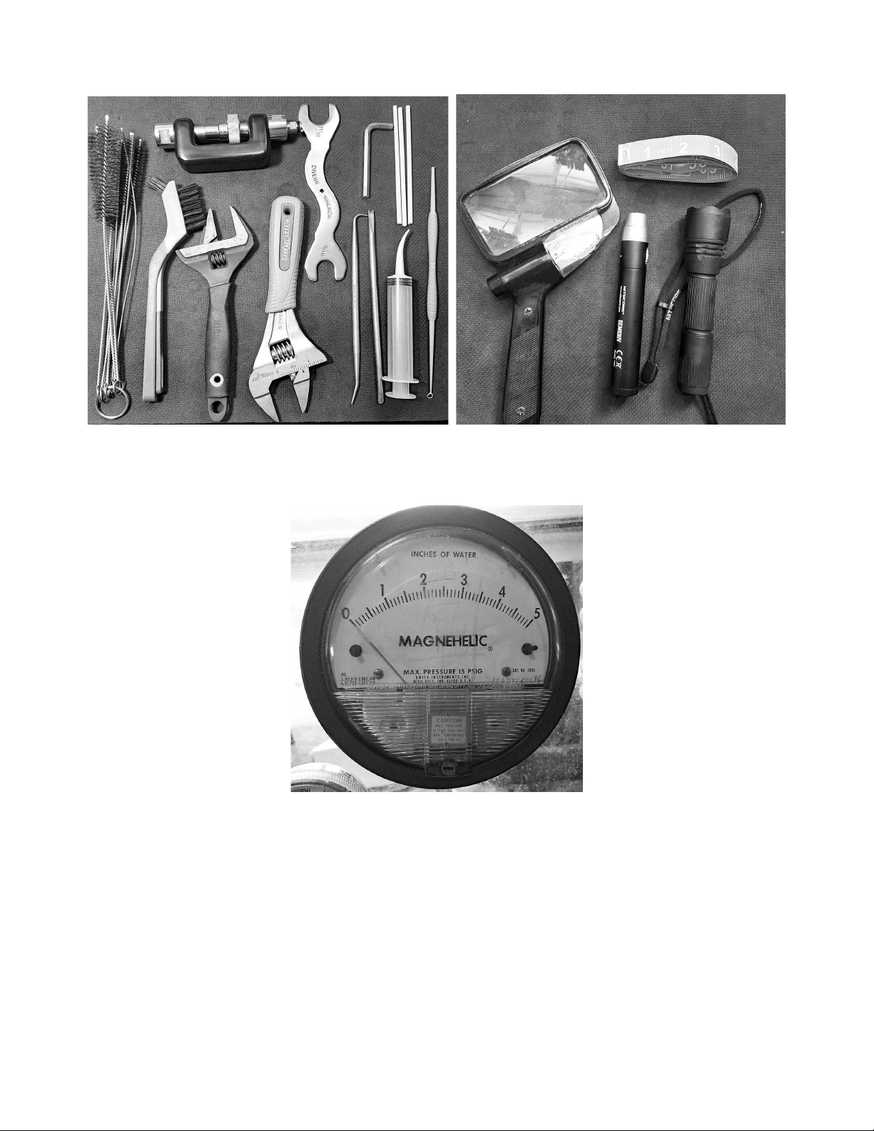
Fig.3Fig.4
RequiredToolsRecommendedTools
Fig.5
Magnehelic

3.PreliminaryTesting
(4)Preliminarytestingoftheregulatorisnecessarytoidentifyanyissueswiththefirstandsecondstagesand
verifytheoverallregulatorfunction.Thistestingwillinclude:
1. Visualinspectionofthefirstandsecondstages
2. Inspectionofthehoses
3. IntermediatePressurecheck
4. CrackingPressureandSecondStageNegativePressureTest
Visual inspectionisdonetoidentifyissuesthatcouldaffectservicingandtoensurethat pressurizingthe
systemwillnotcompromisethesafetyoftheservicetechnician.
Thetechnicianwillcheckallconnectionstomakesuretheyaresecure.
Thetechnicianwillcheckthatonthefirststage,therearenoextrudedorings,andhosesaretight.
ThetechnicianwillchecktherearenodefectstotheSPG.
ThetechnicianwillensurethattheDINassemblyissecure,andtheOringisintactandabletoformaseal.
Thetechnicianwillinspectthefilterforsignsofdiscoloration.
DetailedInspectionofHosesisdonetoensureitissafetopressurizetheregulatorset.
Thetechnicianwillcheckallhoses,lookingforevidenceofpossiblefailure.
Thetechnicianwillcheckallhoseconnectioncrimps.Defectsmustbetakencareofbeforepressurizingthe
system!Replacementofanysuspecthosesisrecommended.
CautionNote:
Defectsinhosesrequirereplacementbeforepressurizingtheregulator!Failuretodoso
mayresultinseriousinjuryordeath!
(5)DetailedVisualInspectionoftheSPGandconnection–ThetechnicianwillchecktheSPGforanysigns
ofcrackingof theface, waterintrusion,and corrosionaround theSPG to thehose connection.Ifusing a
consoleorboot,itisnecessarytoremovetheSPGfromtherubberboot.Oncethisisdone,theHPspool
shouldbeinspectedand,ifnecessary,replaced.
(6)CheckingofIntermediatePressure(IP)–TheIntermediatePressure(IP)ofthesystemshouldbetested
only after the preceding checks have been done to ensure technician safety. Checking of intermediate
pressureisdonebyattachinganintermediatepressuregaugetotheLPpressureinflatorhose.Thesystemis
thenpressurizedwhilepartiallydepressingthepurgebuttonononeofthesecondstages.Depressingthe
purgebuttonslightlyonthesecondstageisdonetopreventfurtherdamagetothesystembyprovidinga
reliefvalveshouldtheIPriserapidlytounsafelevels.Oncethesystemhasbeenpressurized,thepurgeis
released,andtheIPchecked.

CautionNote:
Ifthesecondstageisleakingevenslightly,IPwillbeaffected.Ifthesecondstageis
leaking,turntheadjustmentknobtostopitoruseasecondstagethatisnotleaking
throughwhenpairedwiththefirststage.Itisalsoaclearindicationthatthesecondstage
requiresrebuildingifturningtheadjustmentknobdoesnotstoptheflow.
(7)ThestandardoperatingrangeforthesystemiswithanIPof135PSI.Ideally,thesystemisoperatingat
135PSI+/5PSIandshownosignsof“creep”orinstabilityat3000PSI.
CautionNote:
“Creep”willshowastheIPsteadilyincreasingwhiletheregulatorisnotinuse.Normally
theIPwilldrop510PSIduringabreathorpurgeandthenreturntoitssetting.Itshould
notreturntothesettingandkeepincreasing.Thiswouldindicateaproblemwiththe
highpressureseat,Piston,orsealingorings.
(8)IfthesystemshowsnosignofcreeporIPinstability,itisgenerallynotnecessarytorebuildthe1ststage
withsomeexceptions.
CautionNote:
Iftheunitshowssignsofinternalcorrosionorthefiltershowsevidenceofcontamination,
theunitmustberebuilt!RegardlessoftheIntermediatePressure.
(9)Theregulatorwillrequirerebuildingifsmallbubblesareleakingfrombetweentheturretretainerand
mainbody,fromundertherubbercap,oroutofthehighpressureseatretainer.Knowledgeoffloodingof
the first stage will also require the unit to be rebuilt. Freshwater contains dissolved minerals and other
materialsthat,duetointernalcorrosionovertime,maycausetheregulatortomalfunction.
(10)AftertheIPhasbeenchecked,hosesandregulatorbodyinspected,andSPGevaluated,thesecondstage
inspectioncantakeplace.Itisnecessarytoperformaninspectionofthe1ststageandchecktheintermediate
pressure.Intermediatepressurehasadirectbearingontheperformanceofthesecondstage.IncorrectIP
cangivefalseindicationsastothelevelofservicerequiredonthesecondstage.
CautionNote:
Itmaybenecessarytoservicethesecondstagewhenthe1ststagedoesnotrequire
service.Allinspectionstepsandevaluationsshouldbedonetoensureproperoperationof
theentireassembly.

4.SecondStageEvaluation
NegativePressureandCrackingPressureevaluation–
(1)Thenegativepressuretestverifiesthemainandexhaustdiaphragmsealsaswellascaseintegrity.With
thesupplypressureoff,andattachedtoacylinder,attemptanormalbreathfromthesecondstage.You
shouldbeunabletodrawanyair.Ifaflowisobtained,removethesecondandtrywithathumbovertheair
inlettoit.Ifaflowisstillpresent,theprimaryandexhaustdiaphragmsneedtobecheckedfordamage.Salt
accumulation,sand,anddefectsinthecasewillalsoallowairflowwhentheairinletiscovered.Carefully
checkallofthese.
(2)Crackingpressuretestingismostaccuratelydonewiththe useofamagnahelicgauge.Acontainerof
watercanbeusedbymeasuringthedepthtowhichastagecanbesubmergedfacedownparalleltothe
water.Thisgivesanindicationatwhichlevelofeffortthesecondstagewillopen.Thenormalrangeforthe
adjustablesecondstageis1.0to2.2inchesofwater.Lesspressuremaybedesiredbythediver,buttheinitial
factorysettingof1.1shouldbeused.ThispermitsabreakinperiodfortheLPseat.Itisnormaltoseethis
initialsettingdropastheLPseattakesaset.
SecondStageCaseIntegrity–
(3)Thecaseshouldbeinspectedforsignsofdamage.Scratches,gouges,missingparts,damagedexhaust
ports,orloosefaceplatethatwillnottightenmaybeanindicationofadamagedcase.
(4)Useanegativepressuretest,testthepurgebutton,andlookfordefects.Checktheleverandbreathing
effortknob.Dotheymovefreelyandwithnoindicationofstiffness?Dotheyfeellikethereissandorgritin
them?
(5) A problem with case integrity should be dealt with before starting the rebuild. A defective case will
compromisefinaltestingandposeasafetyhazardtotheuser.
CautionNote:
Adamagedcase,purgecover,ordiaphragmcannotberepaired.Theymustbereplaced.
(6)Havingcompletedtheinitialevaluationanddeterminedserviceisnecessary,therebuildoftheregulator
cantakeplace.
5.SecondStageDisassembly
(1)Inthefollowingsteps,thepartnumbersfromtheschematicwillbeusedwiththeirdescription.Havethe
schematicinfrontofyouwhilefollowingtheinstructions!Besuretokeepalloldpartsorganizedandseparate
fromnewonesintheservicekit!
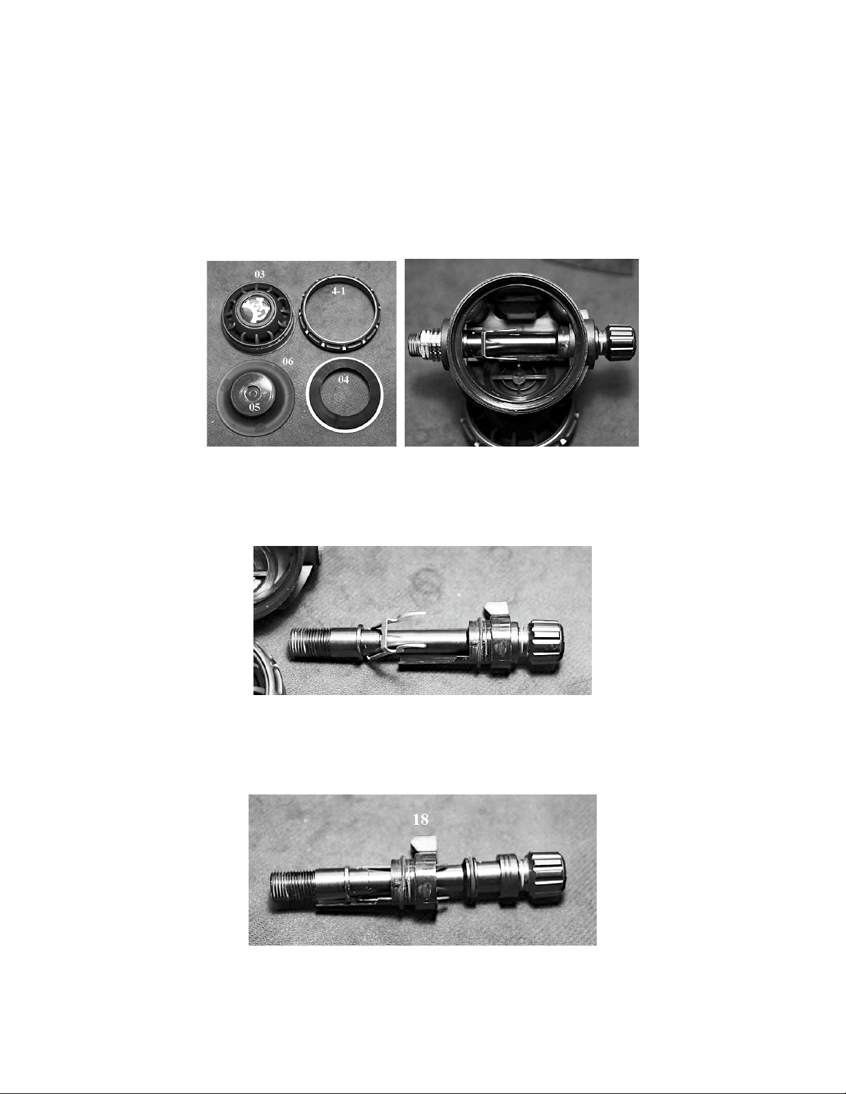
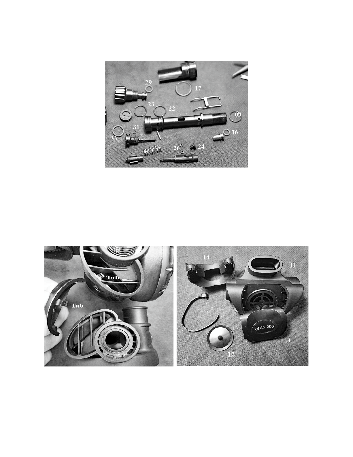
1.RemovetheSecondStagefromthehoseafterdepressurizingthesystem.UnscrewtheCaseCover(41)
fromtheCase(11)andremovetheCover(3),DiaphragmCover(4),andtheDiaphragm(06)andDiaphragm
Disc(05)assembly.Fig.6ThisrevealstheValveSpindleAssemblyinthecase.Fig.7
Fig.6Fig.7
2.RemovetheRetainingNut(08).HoldingtheLever(20)down,slide/pulltheValveSpindleAssemblyoutof
thecaseasoneunit.Fig.8
Fig.8
3.SlidetheVenturiLever(18)offofthespindlewhileholdingdowntheLever(20).Becarefulaftersliding
theVenturiLever(18)offtoallowittocomeupslowly.Fig.9
Fig.9

4. With the lever off, using the brass pick blunt end or another suitable tool, press the Spring Pin (21) out of
the Valve Spindle (19). Notethatthismayrequiresomeforcetoremove.Securethespindleasneeded.
This will allow the Adjusting Screw (30) to be removed. Remove the Rubber Cap (35) from the Adjusting Screw
(30). Using the 3/16th hex wrench, unscrew the Adjusting Spring (34) from the Adjusting Screw. – Fig. 10
Fig. 10
5. Holding the lever upright, use the 1/8th inch plastic or wooden dowel to push the assembly consisting of
the LP seat (24), Shuttle Valve (25), Orings (26), Spring (27), and Counter Balance Cylinder (28) out of the
Spindle. You may hear a slight click as you do this when the LP seat end passes the lever. Fig.11 Analternative
methodistocarefullyremovetheleverbyliftingonelegoutoftheholeandrotatingthespindletoallowthe
othersidetocomeout.DONOTBENDTHELEGSOFTHELEVERTODOTHIS!
Fig.11
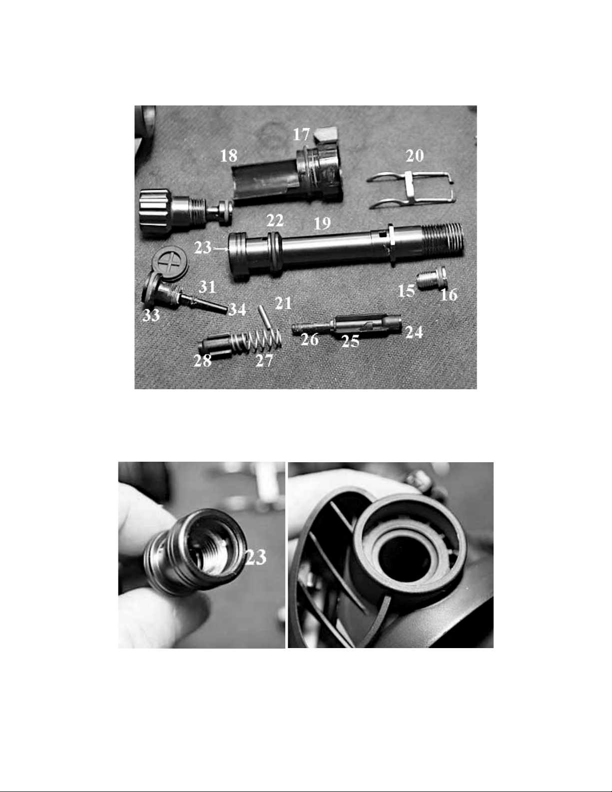
6. Once you have removed the assembly from the Spindle (19), use the slotted end of the inline adjustment
tool to remove the Orifice (15) from the Spindle(19). The photo below shows all of the parts to the Spindle
Assembly. Item Oring (23) is located in a groove on the inside of the Spindle. Fig 12.
Fig. 12
7. Using a brass pick, carefully remove Oring (23) from the Spindle. – Fig.13. Confirm that Oring (09) from
the air inlet side of the Case has been removed from the groove that contains it. Fig. 14
Fig. 13 Fig. 14
8. Using the pinch method or a brass/plastic pick, remove all of the Orings from the Lever (18), Orifice (15),
Shuttle Valve (25), Adjusting Screw (30), and Adjusting Spring (34). Fig. 15. Confirm that all are accounted
for and segregate them with the other replaceable parts.
Fig. 15
9. Carefully cut the zip tie on the Mouthpiece (14) and remove it from the case. Using a blunt pick or
wooden dowel, press the small tab slightly on the adjustment/lever side of the case in the exhaust port to
remove the Cover Exhaust Valve (13). Fig. 16. Becarefulnottosnapthetaboff!Gentlyremovethecover
asyoupressthetab.Donottrytopryitoffwithoutpressingthetab!The Exhaust Valve (12) can be
removed by pulling it out of the hole intact or by cutting the stem inside the case and pulling it out.
Replacing the valve is optional. Fig. 17
Fig. 16 Fig. 17
This completes the disassembly of the second stage. Refer to the Cleaning Section in the Overview for
instructions before assembly.
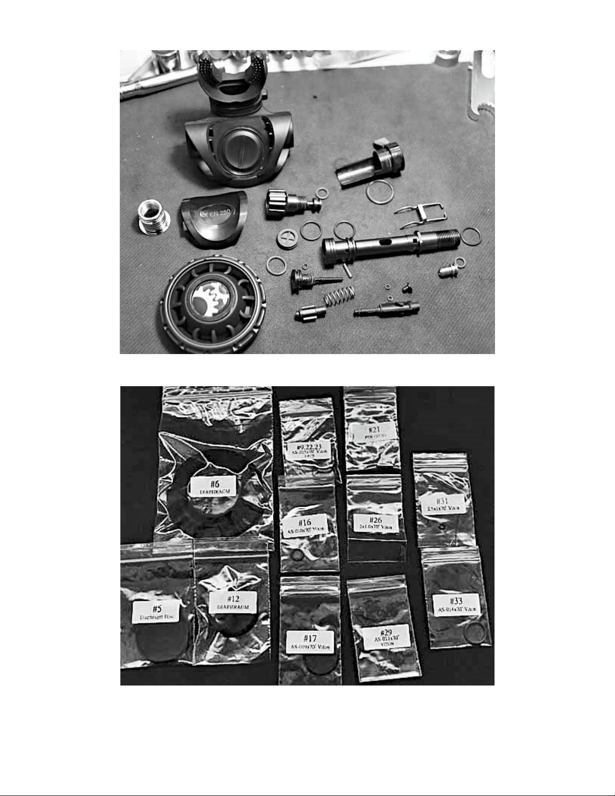
Second Stage disassembled
Second Stage Service Kit

6.SecondStageAssembly
(1) Before starting the assembly of the second stage, complete a thorough inspection of all parts to be re
used. Refer to the Overview Inspection section for details. At this time, open the service kit and lay out the
parts. Use the schematic to identify each part.
(2) Using the method described in the Overview, prepare to lubricate the dynamic orings. Remember to not
use excessive amounts of lubrication.
1. Locate the orings for the following assemblies: Orings (31 and 33) for the Adjusting Spring (34). Lubricate
them and install them on the Adjusting Spring. Place Oring (16) on the Orifice (15). Install Orings (26) on the
Shuttle Valve (25). Install Oring (29) on the Adjusting Screw (30). At this time, the LP Seat (24) can be placed
into the end of the Shuttle Valve (25). Fig. 18.
Fig. 18
2. Install Oring (22) on the Valve Spindle (19) after lubricating it. Install Oring (23) in the interior groove of
Valve Spindle on the side shown in Fig. 19.
Fig. 19
3.UsingtheInLineTool,inserttheOrifice(15)intothethreadedendoftheSpindle(19)–Fig.20,andwhen
thethreadsengage,turnitin34turns.ActualadjustingoftheOrificewillbedonelater.–Fig.21
Fig.20Fig.21
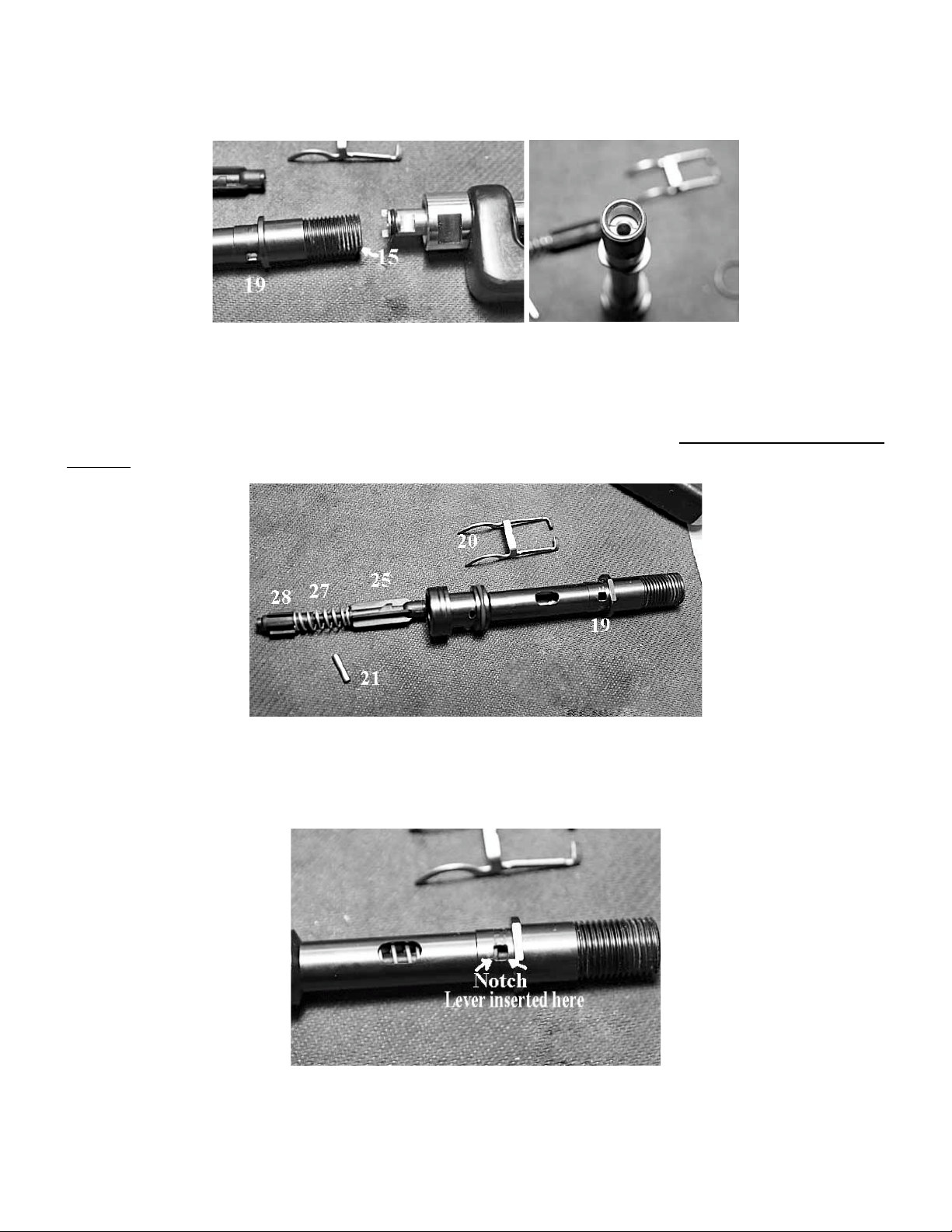
4. Assemble the Shuttle Valve (25), Spring (27), and Counter Balance Cylinder (28). With the assembly
oriented,asshowninFig.22,insertitintotheSpindle(19).Payspecialattentiontothepositionofthenotch
on the Shuttle Valve. This is where the Lever (20) engages the Shuttle Valve. It must be orientedin this
manner.NotealsothepositionoftheholefortheSpringPin(21).–Fig.22.Leverremovedforclarity.
Fig.22
5.Carefullyinserttheassemblytherestofthewayintothespindle.Itiscriticaltomaintainthisorientation.
Slideitinuntilthenotchisclearlyvisibleinthesmallsquarewindow.–Fig.23.
Fig.23

6.Oncethenotchislinedup,carefullyinsertonetabofthelevertoengageitandrotatethespindlesothat
theotherlegoftheleverdropsintothecorrespondingwindowontheotherside.Donotbendthelegsof
thelever!–Fig.24.
Fig.24
7.Allowthelevertocomedowntorestandcarefullysettheassemblyaside.Fig.25.
Fig.25
8.AssembletheAdjustingScrew(30)andAdjustingSpring(34)–Fig.26.Atraceoflubricantonthethreads
ofthesewillhelptoensuresmoothoperation.TheinitialadjustmentontheAdjustmentSpringistohave
approximately1mmofthespringendshowingabovetheendoftheAdjustingScrew(34),asshown.–Fig.
27
Fig.26Fig.27

9.CarefullyinserttheAdjustmentScrew(30)andSpring(34)assemblyintotheSpindle(19)andbeginto
screwitin.Theleverwillriseasthisisdone.Screwtheassemblyinuntilyoucanseeclearlythroughthehole
fortheSpringPin(21).–Fig.28
Fig.28
10.Insertthespringpinandpushitintoplacewiththebluntendofthebrasspick.Fig.29.Thesharpbrass
pickmaybeusedtoguideitin.Anequalamountofpinshouldbepresentoneachside.Ifthisisnotdone,
theVenturiLevermayhanguponthepinthatisstickingtoofarout.
Fig.29
11.PlacethelubricatedOring(17)ontheVenturiLever(18)andslideitontotheSpindle/Leverassembly.
MakesurethatitmovesfreelyaroundtheSpindle(19).Notethepositionoftheleverrelativetotheair
outlet.Fig.30.
Fig.30
Table of contents
Other Dive Gear Express Diving Instrument manuals

Dive Gear Express
Dive Gear Express DGX Gears D6 User manual

Dive Gear Express
Dive Gear Express DGX Xtra First Stage User manual

Dive Gear Express
Dive Gear Express DGX Gears BCI Backup Regulator User manual

Dive Gear Express
Dive Gear Express DGX Gears XTRA User manual

Dive Gear Express
Dive Gear Express DGX Gears FIRST User manual


