Dive Gear Express DGX Gears XTRA User manual

DGX Gears XTRA
First Stage Service Manual

Copyright © 2022 Dive Gear Express
All Rights Reserved
Revision 7 Published 09/23/2022
Revision Date Changes
5d 08/17/2020 Initial publication
6 09/28/2020 Minor technical edits for clarity; edited photos for clarity and
added part numbers; replaced Figs. 26, 30, 32, 33; updated
schematic diagram
7 09/23/2022 Minor technical edits for clarity; replaced Fig 3; removed
Figs. 4 and 5 and renumbered following Figs.; replaced Figs.
23, 29, 35, 36 and 37

1. Overview
(1) The availability of subassemblies and components, repair parts, specialized tools, and maintenance
manuals does not imply qualification to assemble and/or service scuba equipment. Improper service
of dive equipment can lead to severe injury or death. Dive Gear Express recommends that non-qualified
individuals seek professional training/mentoring before attempting repairs or servicing on any diving
equipment.
Failure to follow the procedures outlined herein may result in serious injury or
death!
(2) In the following pages will be found the disassembly, assembly, tuning and troubleshooting steps
for these components. Photos are used throughout to illustrate the procedures.
Please pay special attention to all Caution Notes!
(3) Whenever an item of extra importance needs to be observed, a “Caution Note:” will appear, followed
by the required information. See below.
Caution Note: This must be read and followed!
(4) Included in this manual is a list of recommended/required tools for each disassembly, assembly,
and testing section. They are identified in each section where they are used.
(5) A schematic diagram is located at the rear of this manual. The diagram contains the detailed parts
lists. The diagram also includes the torque specifications for parts where required.
(6) A general troubleshooting guide with space for notes is also included for those using a printed
version. Those who prefer an electronic version should keep detailed notes in an accessible location
for their own observations and service tips, as well as a record of service.
(7) Throughout the text, parts are referenced using the item number on the schematic to facilitate
locating each individual component.
(8) Parts should not be taken out of their packaging until the actual assembly stage is reached, and the
user is ready to lubricate, where necessary, and install them.
(9) Ensure the service area is free of any environmental factors that may cause problems during the
servicing of your regulators. The area must be clean and organized. The use of nitrile gloves is highly
recommended for final rinsing and assembly. This will minimize the risk of skin oils contaminating the
internal components of the regulator.
(10) Ensure that all required servicing/testing air supplies are available and at the proper test pressures
if not using a regulated supply from a single source. “Modified Grade E” air as typically delivered at a
dive shop fill station is preferred.
Caution Note: Only use air from a breathing air source! Do not use a hardware
store shop compressor.

Cleaning and Rinsing - General Considerations
(11) Cleaning and rinsing of the components should be done using clean, fresh water.
(12) Only use degreasers that leave no organic residue (e.g., Extreme Simple Green, Blue Gold Cleaner,
or any clear liquid dish soap that does not contain scents or dyes).
(13) To remove corrosion, use a 50/50 vinegar/water solution and nylon brushes. Areas of heavy
corrosion not removed with vinegar can be addressed with mild phosphoric acid solutions available
from scuba supply houses.
(14) Allow parts to air dry without the use of loop-weave cloths that may leave fibers.
(15) Once all service procedures have been completed and bench testing done, in-water testing in a
confined environment such as a swimming pool is recommended to confirm proper function before
taking the regulator on an actual dive.

Cleaning of Regulator Parts
(16) Cleaning of parts that are going to be reused is one of the most critical steps in servicing the
regulator. As was stated earlier, use the proper solutions for the job at hand. Removal of hydrocarbons
and debris should be accomplished before attempting removal of corrosion. Areas of corrosion are
often also coated with old lubricant or oily contaminants. Before attempting to remove corrosion, use
warm detergent and a soft brush to remove oils and debris. Then use an acidic solution to remove
corrosion. Once corrosion has been removed, inspect parts and repeat detergent washing as needed.
Wearing nitrile gloves throughout the process reduces the risk of contaminating the parts with skin oils.
(17) First, prepare a warm solution of detergent from the list above. Immerse both plastic and metal
parts and agitate thoroughly. Protect critical delicate parts (such as the Piston knife edge) by washing
them separately or isolating them in a small plastic container with holes. Use a soft nylon brush and/or
soft rags soaked in detergent to scrub away visible debris and contaminants. Corrosion will likely not
be removed during this step. Rinse repeatedly in clean water.
(18) Now address visible corrosion by submerging metal parts only in a 1:1 dilution of white vinegar
and hot water. Do not immerse plastic parts in an acid bath - it will degrade the plastic and make it
more susceptible to cracking. Agitate the parts occasionally and allow parts to stand in the acidic
solution for ten minutes. Wearing gloves, remove and inspect parts, and reimmerse them for an
additional ten minutes if visible corrosion is still noted. Removal of corrosion will leave bare brass
behind, which will not affect regulator function, but will necessitate more frequent future inspection
and service. After the acid bath, rinse all metal parts thoroughly.
(19) Best practice is to neutralize any possible residual acid remaining in crevices and threads, by
immersing all acid-treated parts in a neutralizing solution of warm water and sodium bicarbonate
(baking soda) in a ratio of 1 tablespoon per gallon of water. After a brief neutralizing soak, again rinse
all parts thoroughly. In areas with high mineral content in the water, a final rinse with distilled water
should be considered. A plastic colander is excellent for drainage after rinsing. For very small parts, a
mesh strainer for sink drains works well. Often sold as a set, they are inexpensive and can be used for
many types of regulator components. Again, protect delicate parts from contact with hard metal
surfaces. Retained final rinse water should be allowed to stand and examined for a surface sheen
indicative of residual hydrocarbon residue. If noted, return to step (17) above.
(20) After washing and rinsing the regulator parts, allow them to air dry. Using a drying rack will facilitate
this. Do not lay the parts on a paper towel or loop-weave cloth towel. Doing so runs the risk of having
fibers stick to them that will cause issues with sealing. If a cloth is used as an aid to drying, make sure
to use a tight, flat weave lint-free cloth that has previously been well washed to remove fabric sizing.

Inspection After Cleaning
(21) Before assembling the regulator, it is necessary to inspect all the cleaned components. Using a
magnifying glass or inexpensive USB microscope, ensure all parts are clean and contaminant-free, and
check the components for damage that may have been hidden by corrosion or lubricant. Look for
scratches that may affect the sealing of the regulator.
(22) Lay all parts out on your padded work surface following the schematic. A rubber or silicone mat of
suitable size that is clean and free of contaminants works well for this.
(23) Now that all parts have been cleaned and checked, the assembly can begin. Remove the new parts
from the service kit bag and lay them out following the schematic, matching them to the old parts for
size. Then make sure all old parts that are to be replaced have been discarded or segregated.
Caution Note: Removing parts from their packaging before they are to be used
runs the risk of mixing them up. Some O-rings are very close in size but are not
interchangeable! Keep parts in their packaging until you are ready to exchange
them for their used equivalent.
(24) As with the parts that have been cleaned, it is a good idea to inspect the new parts as well. Inspect
the HP Seat to ensure it is free of any defects. Check all O-rings and inspect them as you use them for
nicks or imperfections. Inspect the washers to ensure they are free of burrs or other defects that could
affect their function. It is critical to use the parts list on the schematic to ensure that all new parts are
present and accounted for in their required quantities.
(25) Lubrication can be overdone.Doing so runs the risk of trapping excess dirt or debris on the parts.
One way of reducing the risk of overdoing it is to use the lube-in-a-bag method - Fig. 1
Fig. 1
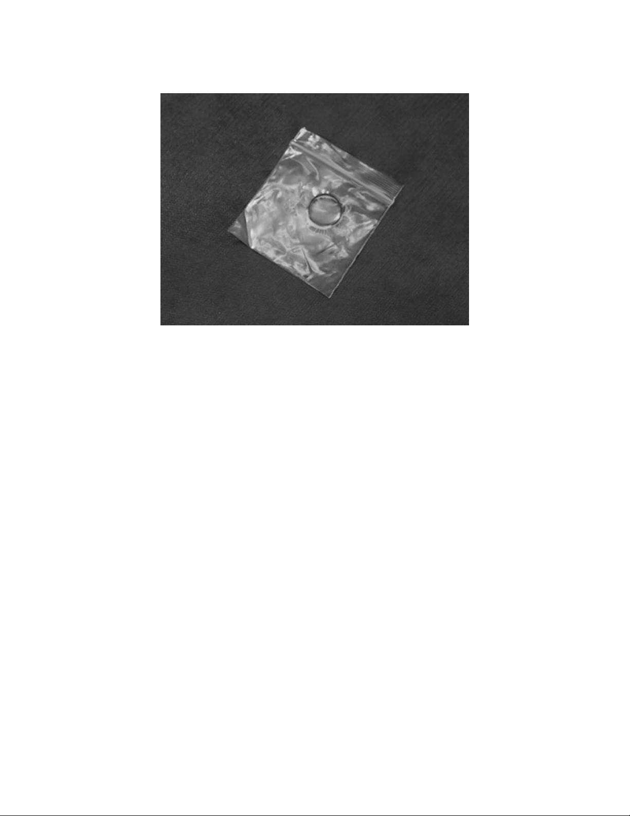
This involves using a small clean plastic bag containing a small amount of lubricant. The O-ring is
inserted into the bag, worked around to evenly coat with lube while squeezing off excess, then taken
out of the bag and used in its location - Fig. 2.
Fig. 2.
(26) Another way is to apply a small amount of lubricant to the gloved index finger and massage the O-
ring between the thumb and index finger.
(27) Under most circumstances, a lubricant should be used very sparingly or not at all. In nearly all
scuba applications, if you can see the lubricant, too much has been applied. Before using any lubricant,
any existing lubrication should be removed before new is applied. In dynamic applications, it is used to
reduce excessive wear. Static O-rings do not generally require the use of lubricant.
(28) Do not unnecessarily lubricate parts. Certain parts are specifically noted to be installed without
lubrication. Not lubricating unnecessarily helps to keep those parts clean and free of debris that might
otherwise cling to the lubricant.
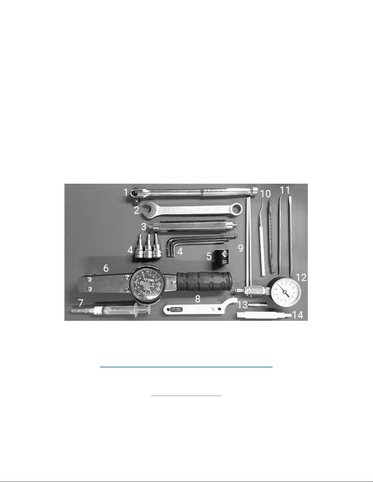
2. Tool List - Fig. 3
1. 3/8”Breaker Bar or Ratchet Handle
2. Open End Hose or Adjustable Wrench
3. Vise Handle (First Stage Body Holding Tool)
4. 4, 5 and 6mm Hex Sockets and Hex Keys
5. 3/4” | 19mm Socket
6. 0-300 in-lb Torque Wrench
7. Tribolube 71
8. #5 Hook Spanner with 0.240 or 0.156 Pin
9. Thin Wooden Dowels
10. Thin Brass and Heavy Nylon Picks
11. Blunt Brass Pick and Blunt Brass Spade
12. Intermediate Pressure Gauge
13. Piston Bullet
14. Piston Bushing Tool
Fig. 3
(1) The First Stage Body Holding Tool, Thin Jaw Adjustable Wrench, Spanner Wrench and Brass O-Ring
Pick Set can be found at Dive Gear Express using the link below.
https://www.divegearexpress.com/tools/scuba-tools
(2) Tools may also be purchased from Scuba Tools at the link below.
www.scubatools.com
(3) Additional useful items are a magnifying glass or inexpensive USB microscope, nitrile gloves and,
to aid in rinsing, a plastic colander and small mesh strainers for smaller parts.

3. Preliminary Testing
(1) Preliminary testing of the regulator is necessary to identify any issues with the first and second
stages and verify the overall regulator function. This testing will include:
1. Visual inspection of the first and second stages
2. Inspection of the hoses
3. Intermediate Pressure (IP) check
4. Cracking effort and second stage negative pressure test
Visual inspection is done to identify issues that could affect servicing and to ensure that pressurizing
the system will not compromise the safety of the service technician.
Check all connections to make sure they are secure.
Check that on the first stage, there are no extruded O-rings, and hoses are tight.
Check that there are no defects in the SPG.
Ensure that the DIN assembly is secure, the O-ring is intact and is able to form a seal.
The technician will inspect the filter for signs of verdigris corrosion or discoloration suggestive of water
intrusion.
Detailed inspection of hoses is done to ensure it is safe to pressurize the regulator set. Look for
evidence that might lead to hose failure. Check all hose connection crimps. Defects must be addressed
before pressurizing the system! Replacement of any suspect hoses is recommended.
Caution Note: Defects in hoses require replacement before pressurizing the
regulator! Failure to do so may result in serious injury!
(2) Check the SPG for any signs of cracking of the face, water intrusion, and corrosion around the SPG-
to-hose connection. If using a console or boot, it is necessary to remove the SPG from the rubber boot.
Once this is done, the HP spool should be inspected and, if necessary, replaced.
(3) The Intermediate Pressure (IP) of the system should be tested, after the preceding checks have
been done to ensure technician safety. Checking of IP is done by attaching an IP gauge to the low
pressure (LP) inflator hose. The system is then pressurized while partially depressing the purge button
on one of the second stages. Depressing the purge button slightly on the second stage prevents
damage to the system by providing a relief valve should the IP rise rapidly to unsafe levels. Once the
system has been pressurized, the purge is released, and the IP checked.

Caution Note: If the second stage is leaking even slightly, IP will be affected. If
it is leaking, turn the adjustment knob to stop the flow or use a second stage that
is not leaking when paired with the first stage. It is a clear indication that the
second stage requires rebuilding if turning the adjustment knob does not stop
the flow.
(4) The standard operating range for the system is with an IP of 135 psi. Ideally, the system is operating
at 135 psi +/- 5 psi and show no signs of “creep” or instability at 3000 psi.
Caution Note: “Creep” will show as steadily increasing IP while the regulator is
not in use. Normally the IP will drop 5-10 psi during a breath or purge and then
return to its setting. It should not return to the setting and keep increasing. This
indicates a problem with the HP Seat, Piston, or sealing O-rings.
(5) If the system shows no sign of creep or IP instability, it may not be necessary to rebuild the first
stage, with some exceptions.
Caution Note: If the unit shows signs of internal corrosion or the filter shows
evidence of contamination, the unit must be rebuilt, regardless of the IP.
(6) The regulator will require rebuilding if small bubbles are leaking from between the turret retainer
and main body, from under the rubber cap, or out of the high-pressure seat retainer. Knowledge of
flooding of the first stage will also require the unit to be rebuilt. Even fresh water contains dissolved
minerals and other materials that, over time, may cause the regulator to malfunction.
(7) After the IP has been checked, hoses and regulator body inspected, and SPG evaluated, the service
of the first stage can take place.
4. First Stage Disassembly
(1) Additional tips for performing disassembly of the XTRA First Stage can be found in our video at:
https://www.youtube.com/watch?v=KOl-oxsuBAE
(2) Ensure the system is depressurized. Document the position of all hoses and port plugs. The use of
small, clean containers to hold parts is recommended.
(3) In the following steps, the part numbers from the schematic will be used with their description. The
numbers on the photos also correspond with the parts list on the schematic. Items in the service kits
are identified in the same way. Have the schematic in front of you while following the instructions. Be
sure to keep all old parts organized and separate from new ones in the service kit. The old washers and
O-rings marked with an asterisk (*) will be replaced with new ones from the service kit and the
remaining parts will be cleaned and reused.
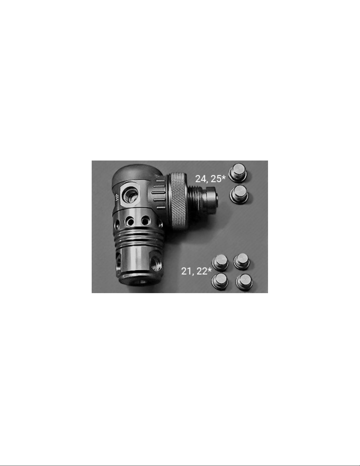
1. Remove all hoses and port plugs (21, 24) with O-rings (22*, 25*) - Fig. 4.
Fig. 4
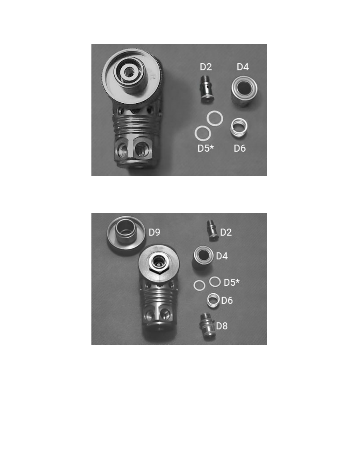
2. Remove the Shutter Valve (D2) using a 4mm hex and Shutter Crown (D4), which contains the Spring
(D6) and two small nylon Washers (D5*) - Fig. 5.
Fig. 5
3. Remove the Retainer Housing (D8) with the 4mm hex and lift the Handwheel (D9) from the body -
Fig. 6.
Fig. 6
4. Insert the First Stage Body Holding Tool into one of the high pressure ports and clamp the tool into
a vise - Fig. 7.
NEVER CLAMP THE FIRST STAGE BODY INTO THE JAWS OF A VISE!
Fig. 7
Caution Note: Clamping the body of the regulator into the jaws of a vise may
result in damage to the body that will require replacement of the regulator.
Always use a first stage holding tool to secure the regulator.
5. Using a 3/4” | 19mm socket and ratchet loosen the Filter Retainer (D10) - Fig. 8. Be sure to hold the
socket firmly so that it does not slip. Using steady, even pressure remove the Retainer and Saddle (08).
Fig. 8

6. Carefully remove the O-rings (D1*, D3*, D7*) from the Shutter Valve, Shutter Crown, Retainer Housing
and Filter Retainer. Use the pinch method and a brass or nylon pick. Do not use a steel pick that could
damage the sealing surface. Remove the Filter (D11) and set aside. Retain the Spring (D6) and items
listed above with the parts to be reused - Fig 9. The washers and O-rings will be replaced.
Fig. 9
Caution Note: Take whatever steps are necessary for keeping track of items that
are part of an assembly. This degree of organization will reduce the risk of
mistakes that can result in a failure of the regulator.
7. Using the Multi-Tool, carefully remove the rubber End Cap (34) - Fig. 10. This exposes the HP Seat
Retainer (33) - Fig. 11.
Fig. 10Fig. 11
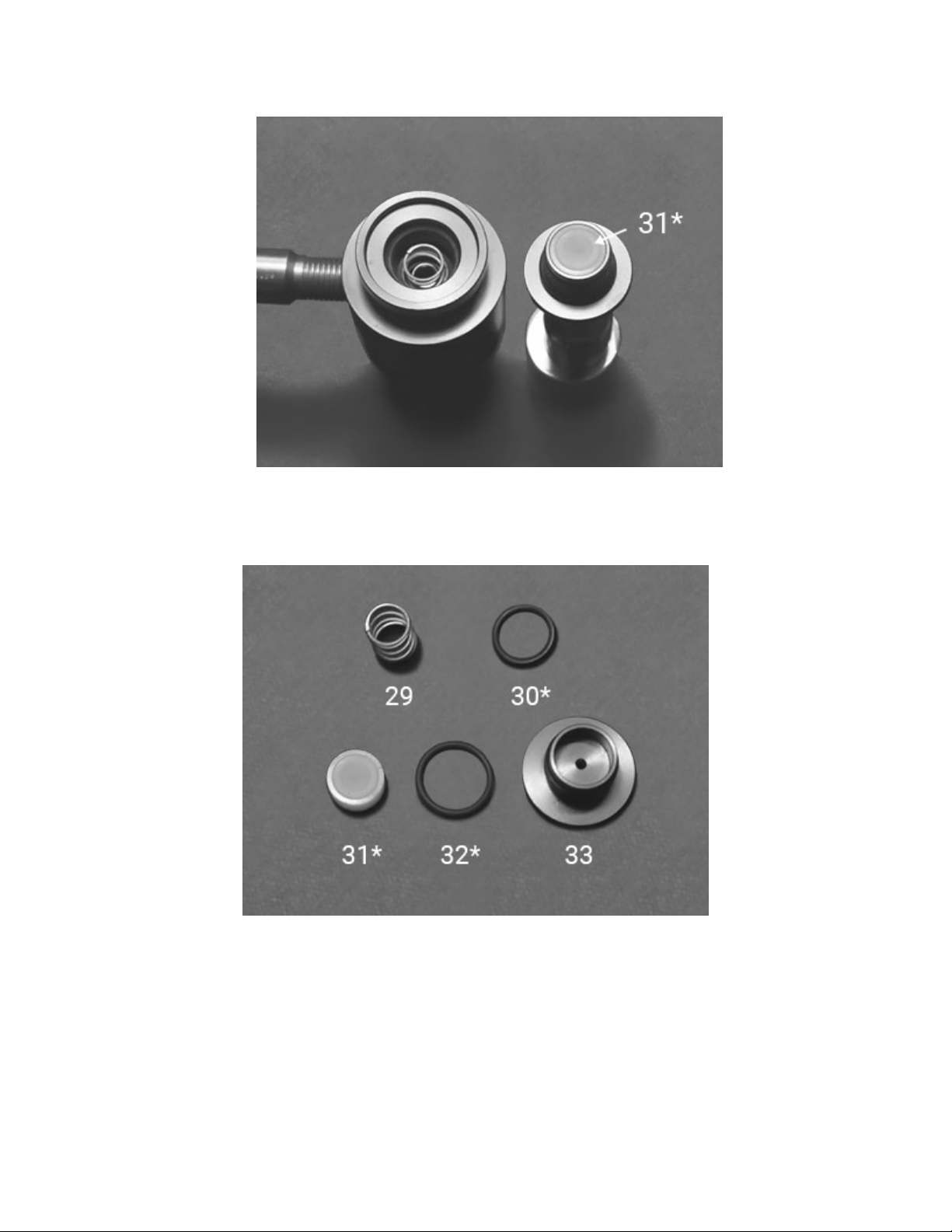
8. Loosen the HP Seat Retainer with a 5mm hex wrench and remove it from the body, exposing the HP
Seat (31*) - Fig. 12.
Fig. 12
9. Push out the HP Seat with a blunt pick or thin hex key, remove the O-ring (32*) and Spring (29).
Remove O-ring (30*) with a brass or nylon pick from its groove in the body of the regulator - Fig. 13.
Fig. 13

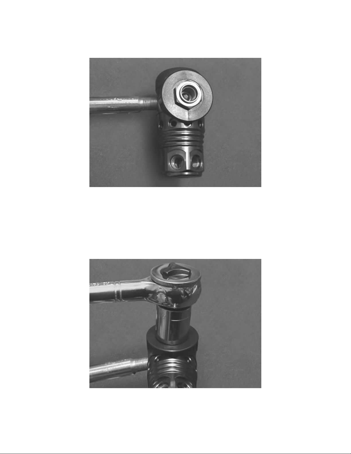
10. Using the universal wrench or a pin spanner with an appropriate pin, and with the first stage handle
secure - Fig. 14, loosen the End Cap (19)/Port Swivel (23) assembly so that a gap is visible - Fig. 15.
Fig. 14Fig. 15
11. Holding the regulator vertical, with the end cap/turret on the bottom, unscrew the assembly from
the Body (11) - Fig. 16. This allows access to the Washer (12*), Spring (13), Washer (12-1*), and Piston
(14) - Fig. 17.
Fig. 16Fig. 17

12. Remove O-ring (15*) from the piston using the pinch method to avoid scratching the piston sides -
Fig. 18.
Fig. 18
13. Carefully remove the following components from the HP side of the regulator Body: Washer (28),
O-ring (27*), and Teflon Washer (26*) using the Piston Stem Bushing Assembly Tool - Fig. 19. Turn the
Body over and remove the other O-ring (27*) with a nylon pick - Fig. 20. Do not use a metal tool to
remove this O-ring.
Fig. 19 Fig. 20

14. Disassemble the turret by inserting a first stage handle into one of the low pressure ports, then using
a 6 mm hex wrench to unscrew the Nut (16) from the Port Swivel (23) - Fig. 21.
Fig. 21
15. This allows access to the Washer (17a). Remove the Washer. Pull the End Cap from the Port Swivel
and remove the Washer (17b) and O-ring (20*) from the Port Swivel - Fig. 22. Take note of the Washers.
The smaller one (a) goes into the End Cap and the larger (b) onto the Port Swivel at reassembly.
Fig. 22
This completes the disassembly of the XTRA First Stage.
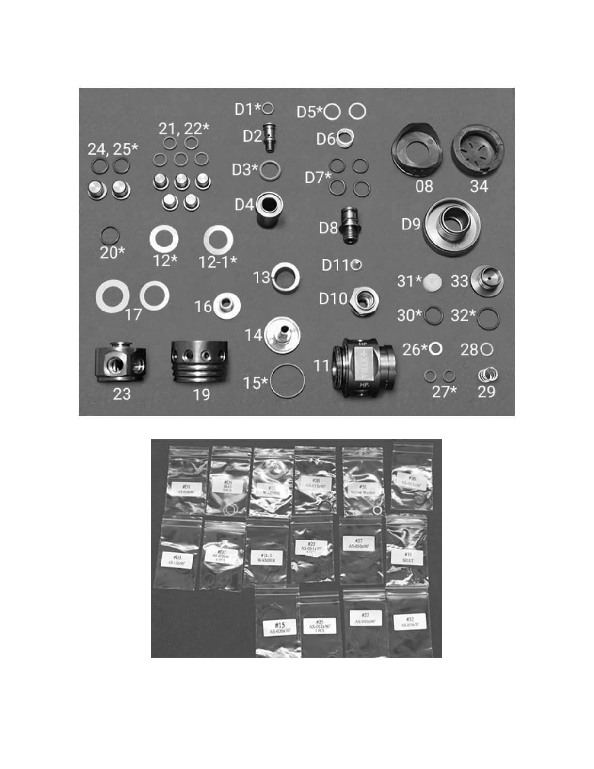
(4) The photographs below show the disassembled first stage - Fig. 23 and First Stage Service Parts
Kit - Fig. 24. All the parts not in the service kit need to be washed, rinsed and dried, as discussed
previously. O-rings and washers that will be replaced with new from the service kit should be discarded.
Fig. 23
Fig. 24

5. First Stage Assembly
(1) Additional tips for performing reassembly of the XTRA First Stage can be found in our video at:
https://www.youtube.com/watch?v=1b8Xx3VVf2o
(2) Before starting the first stage assembly, complete a thorough inspection of all parts to be reused.
Refer to the Overview Inspection section for details. At this time, open the service kit and lay out the
parts. Use the schematic diagram to identify each part.
Caution Note: Only use enough lubricant to lightly coat the O-rings and ensure no
debris is trapped on them.
1. The first step in assembling the now cleaned first stage is to assemble the turret. Lubricate the O-
ring (20*) and install it on the Port Swivel (23) - Fig. 25, along with the larger Washer (17b) - Fig. 26.
Fig. 25Fig. 26
Other manuals for DGX Gears XTRA
2
Table of contents
Popular Industrial Equipment manuals by other brands

Tektronix
Tektronix DAS 92DM930 instruction manual

TWS AUTOMATION
TWS AUTOMATION PICK & PLACE QUADRA DVC user manual

Global Industrial
Global Industrial HEPA 641754 user manual

Swire Energy Services
Swire Energy Services Mud-Skips Instructions for the Safe Use

Mankenberg
Mankenberg M XTRA RP 840 operating manual

Aerotech
Aerotech ASR1300 Hardware manual

SANKI
SANKI S-CON MINI SCLV Operating and service manual

Sure-Feed Engineering
Sure-Feed Engineering ECO Series Operations & parts manual

turck
turck TN-IOL2 Series Instructions for use

Zionair
Zionair SB19A Assembly and user instructions

SPIETH
SPIETH MSW Series Assembly instructions

Rexnord
Rexnord Falk Freedom M20 Installation & maintenance


