SPIETH MSW Series User manual
Document
ma-mswg-en1817
Page 1 of 7
Assembly Instructions
MSW from M72 to M140
The Assembly Instrcutions are also available for download at www.spieth-me.de. In case of any questions, please
contact Spieth-Maschinenelemente GmbH & Co. KG directly.
Legal:
Spieth-Maschinenelemente GmbH & Co. KG, Alleenstraße 41, D - 73730 Esslingen
Phone +49 711 930730 0 - Fax +49 711 930730 7
E-Mail: info@Spieth me.de - Web: www.spieth-me.de
KG: Esslingen HQ, Stuttgart county court, company register sect. A 210689
PhG: Spieth-Beteiligungs-GmbH, Esslingen HQ, Stuttgart county court, company register sect. A 210636
Managing director: Dipl.-Ing. Alexander Hund
©Spieth
Proprietary
notice
ISO 16016
Previous document: ma-mswg-en1604
See
www.spieth-me.de/english/service-download/catalogue-instructions/
Successive document: N/A
Created: 27 Apr 2018/Fd
For any questions, requests or suggestions, please contact
info@spieth-me.de
Checked: 27 Apr 2018/Ax
Original version of assembly instructions
For
Series
Components
Spieth locknuts
(precision locknuts)
MSW from M72
MSW 72.60
MSW 85.60
MSW 105.66
MSW 125.72
MSW 140.78

Document
ma-mswg-en1817
Page 2 of 7
Assembly Instructions
MSW from M72 to M140
©Spieth
Proprietary
notice
ISO 16016
Previous document: ma-mswg-en1604
See
www.spieth-me.de/english/service-download/catalogue-instructions/
Successive document: N/A
Created: 27 Apr 2018/Fd
For any questions, requests or suggestions, please contact
info@spieth-me.de
Checked: 27 Apr 2018/Ax
Assembly instructions for Spieth Locknuts
Table of Contents
Assembly instructions for Spieth Locknuts...................................................................................................................2
Table of Contents .....................................................................................................................................................2
1 Information about Spieth Locknuts......................................................................................................................3
1.1 General information .....................................................................................................................................3
1.2 Safety notices ...............................................................................................................................................3
2 Description of Spieth Locknuts.............................................................................................................................4
2.1 Structure.......................................................................................................................................................4
3 Assembling Spieth Locknuts .................................................................................................................................4
3.1 Preparing for assembly.................................................................................................................................4
3.2 Ambience/Environment ...............................................................................................................................5
3.3 Assembly process .........................................................................................................................................5
4 Disassembling Spieth Locknuts.............................................................................................................................7
5 Maintenance and servicing of Spieth clamping sleeves.......................................................................................7

Document
ma-mswg-en1817
Page 3 of 7
Assembly Instructions
MSW from M72 to M140
©Spieth
Proprietary
notice
ISO 16016
Previous document: ma-mswg-en1604
See
www.spieth-me.de/english/service-download/catalogue-instructions/
Successive document: N/A
Created: 27 Apr 2018/Fd
For any questions, requests or suggestions, please contact
info@spieth-me.de
Checked: 27 Apr 2018/Ax
1Information about Spieth Locknuts
1.1 General information
Spieth locknuts are precision parts and require careful handling. Follow the information in these assembly
instructions and the operating instructions. Failing to comply with them may significantly impact functionality and
service life.
To apply the locking force, use only original Spieth clamping screws. Do not actuate the clamping screws until the
locknut thread has been fully screwed onto the spindle thread. Otherwise, damage such as ductile deformation
may occur on the locknut and render it unusable. Spieth-Maschinenelemente GmbH & Co. KG assumes no liability
for damage from improper handling, incorrect installation, or unauthorised structural changes.
1.2 Safety notices
Spieth locknuts are intended for use on threaded spindles. Please follow all relevant safety notices.
Caution!
Any work carried out with or on the locknut needs to follow the "safety first" guideline!
During operation, keep your hands away from the working area of the locknut!
Prior to any assembly work, switch off all machine drives!
Secure the machine against accidental power-up!
Prior to commissioning the machine, install all safety devices!
Only expert personnel are allowed to perform assembly work on Spieth locknuts. Using Spieth locknuts is only
admissible according to specifications. Spieth-Maschinenelemente GmbH & Co. KG assumes no liability for
violations of the operating instructions or safety notices. This also applies to incorrectly interpreting or circulating
these notices and to incorrect assembly or maintenance.
The locknuts described here are state of the art at the time these assembly instructions are printed. Subject to
changes based on evolved technologies. For international deliveries, follow the safety regulations applicable in
the target country.

Document
ma-mswg-en1817
Page 4 of 7
Assembly Instructions
MSW from M72 to M140
©Spieth
Proprietary
notice
ISO 16016
Previous document: ma-mswg-en1604
See
www.spieth-me.de/english/service-download/catalogue-instructions/
Successive document: N/A
Created: 27 Apr 2018/Fd
For any questions, requests or suggestions, please contact
info@spieth-me.de
Checked: 27 Apr 2018/Ax
2Description of Spieth Locknuts
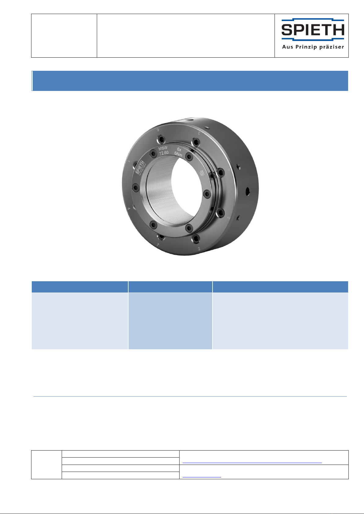
2.1 Structure
Spieth locknuts bodies
Fig 1: Schematic representation similar to
Spieth MSW series locknuts
Radial boreholes for pin spanner DIN 1810 - B
Spieth pretensioning bolts
Spieth clamping screws
Locking thread pin
Identifying feautures (for original Spieth locknuts)
Spieth logo
Name
Batch number
Locking torque MSfor clamping screws
The Spieth MSW series locknuts are assemblies consisting of locknut bodies and clamping screws. The thread
inside the locknut body is interrupted by a groove, separating the locknut body into a load and a locking part. A
diaphragm connects load and locking part.
3Assembling Spieth Locknuts
3.1 Preparing for assembly
Remove Spieth locknuts from their packaging right before assembly. As hand perspiration can cause corrosion,
ensure to keep your hands dry and clean and/or to always wear protective gloves for assembly.
Please note:
For environmental reasons, please comply with applicable statutory regulations and guidelines when
disposing of packaging materials.
In case of damage to packaging components, check the locknuts for damage and remove any contamination.
The preservative used is compatible with all conventional machine oils. If in doubt, check the preservative's
compatibility.
For an optimum mode of action of Spieth locknuts, remove the thin wax-like film of preservative from the contact
surfaces using a lint-free cloth. Directly afterwards, use machine oil without friction-reducing additives to lightly
oil the component and protect it from corrosion.

Document
ma-mswg-en1817
Page 5 of 7
Assembly Instructions
MSW from M72 to M140
©Spieth
Proprietary
notice
ISO 16016
Previous document: ma-mswg-en1604
See
www.spieth-me.de/english/service-download/catalogue-instructions/
Successive document: N/A
Created: 27 Apr 2018/Fd
For any questions, requests or suggestions, please contact
info@spieth-me.de
Checked: 27 Apr 2018/Ax
3.2 Ambience/Environment
During assembly, ensure that...
the assembly location is clean and free from dust,
the components have no contact with corrosive media,
foreign bodies such as sand, sawdust, fluff, etc. are kept away from the component,
metal filings (in particular from machining tools such as files, etc.) are kept away from the component.
Caution!
Contamination can significantly impact the functionality and service life of Spieth locknuts.
For best results, use a suitable, enclosed space for assembly and proceed swiftly. If this is not possible, make sure
to protect the components from ambient contamination and from damage.
3.3 Assembly process
Essentially, assembly is a 4-step process:
1. Screwing
2. Aligning
3. Locking
4. Pretensioning
For an optimum mode of action of Spieth locknuts, perform all four assembly steps in the specified order.
Caution!
To apply the locking force, use only original Spieth clamping screws. Do not actuate the clamping
screws until the nut thread has been fully screwed onto the spindle thread.
Otherwise, damage such as plastic deformation may occur on the locknut and render it unusable.
Use only the following assembly process for assembling Spieth MSW series locknuts:
3.3.1 Screwing:
First clean, lightly oil and then screw the locknut onto the spindle thread but avoid contact with the end face. It is
recommended to lightly oil the spindle thread, too. Since the nut thread is coordinated with the clearance of the
spindle thread, you can easily do this manually. We recommend maintaining sufficient distance to the planar
support while ensuring that the locking part of the nut body is fully screwed onto the spindle thread.

Document
ma-mswg-en1817
Page 6 of 7
Assembly Instructions
MSW from M72 to M140
©Spieth
Proprietary
notice
ISO 16016
Previous document: ma-mswg-en1604
See
www.spieth-me.de/english/service-download/catalogue-instructions/
Successive document: N/A
Created: 27 Apr 2018/Fd
For any questions, requests or suggestions, please contact
info@spieth-me.de
Checked: 27 Apr 2018/Ax
3.3.2 Aligning:
Tighten the clamping screws stepwise and crosswise. Regularly check how much play the nut has on the thread.
Repeat this process until the movement is nearly free of clearance. This aligns the end face of the locknut with
the spindle axis and requires very little torque on the clamping screws (normally far less than 1Nm); we
recommend using a manual tool (screwdriver or spanner) for sensitive tightening.
3.3.3 Placing and locking:
Place locknut on planar support and lock by tightening the clamping screws stepwise and crosswise until the
specified locking torque MS(see design guide). For optimum effectiveness we recommend tightening the
clamping screws in three steps (50%, 75% and 100% of the specified locking torque MS).
3.3.4 Pretensioning (1):
To reduce subsidence, first use a suitable tool (see design guide) and an increased bolting torque MBe to tighten
the pretensioning bolts stepwise and in the specified order against the planar support; then undo it. Depending
on the resilience of the connecting components, the increased bolting torque MBe of the locknut may amount up
to 1.2 to 1.5 times the calculated bolting torque MB(see design guide)
3.3.5 Pretensioning (2) and locking the pretensioning bolts
Now tighten the pretensioning bolts with the calculated bolting torque MB(see design guide/see note). For
optimum effectiveness we recommend tightening the clamping screws in three steps (50%, 75% and 100% of the
calculated bolting torque MB).
Secure pretensioning bolts against undoing by tightening the locking thread pins. Then check locking torque MSof
the clamping screws.
Pretension and lock Spieth locknuts only if used with original Spieth clamping screws and if the nut thread is fully
screwed onto the spindle thread.
In case of maximum demands on spindle concentricity you can individually adjust the pretensioning bolts to
achieve the desired result. Following specified assembly, Spieth locknuts are ready for use immediately.
For more information on assembly, please see the relevant assembly instructions, available at www.spieth-me.de.

Document
ma-mswg-en1817
Page 7 of 7
Assembly Instructions
MSW from M72 to M140
©Spieth
Proprietary
notice
ISO 16016
Previous document: ma-mswg-en1604
See
www.spieth-me.de/english/service-download/catalogue-instructions/
Successive document: N/A
Created: 27 Apr 2018/Fd
For any questions, requests or suggestions, please contact
info@spieth-me.de
Checked: 27 Apr 2018/Ax
4Disassembling Spieth Locknuts
If handled correctly, Spieth locknuts can be reused several times. Due to the adjustments made, once a locknut
has been locked onto a spindle thread you can only reuse it on the same thread after they have been
disassembled.
Caution!
Unlock all the clamping screws stepwise and crosswise to avoid overstraining the screws. Otherwise,
the screws may fracture or the locknut or its adjoining components may be damaged.
To disassemble, proceed in reverse assembly order.
1. Unlock: Unlock the pretensioning bolts by undoing the locking thread pins.
2. Declamping: Slightly undo pretensioning bolts; then declamp them stepwise in the specified order.
3. Undo: Slightly undo clamping screws; then declamp them stepwise and crosswise.
4. Unscrew: Unscrew locknut by hand from threaded spindle.
If used as intended the diaphragm will open the interlocked thread flanks during unlocking. This restored joint
play makes it easy to unscrew the locknut manually without damaging the threaded spindle.
Please note:
Following complete disassembly, slightly (manually) tighten the loosened clamping screws until they
are flush. In any case, avoid tightening the clamping screws without a fully covered nut thread.
To enable later reuse, clean, preserve, and store Spieth locknuts correctly. Prior to reuse, proceed as detailed in
section 3.1, "Preparing for assembly" ff.
If non-original Spieth spare parts are used, Spieth-Maschinenelemente GmbH & Co. KG assumes no liability or
warranty.
5Maintenance and servicing of Spieth clamping sleeves
Spieth clamping sleeves are low-maintenance. If used as intended, Spieth clamping sleeves provide permanently
precise pretensioning and positioning of the bearing on a spindle shaft.
We recommend periodic visual inspections of the clamping sleeves for potential damage.
Follow general safety notices when using Spieth clamping sleeves.
Caution!
Never touch actively rotating components. Take protective measures against accidental contact.
If you notice irregularities with the Spieth clamping sleeves during operation, immediately switch off the
machine's drive.
This manual suits for next models
5
Table of contents
Other SPIETH Industrial Equipment manuals


Popular Industrial Equipment manuals by other brands

Milnor
Milnor TS1L/R Installation

Festo
Festo VMPA1-FT-NW 10 Series Assembly instructions

Siemens
Siemens SIVACON 8PS BD2 Series installation instructions

Huawei
Huawei FusionDC1000A quick guide

FLENDER
FLENDER FASTEX EC210 Assembly and operating instructions

SCHUNK
SCHUNK ROTA-S flex 550 Assembly and operating manual


