Mankenberg M XTRA RP 840 User manual

Operating manual
Pilot-controlled pressure regulators
Sheet no. RP/4.1.201.1.1 issue 01.07.2020
© 2020 MANKENBERG GmbH

© 2020 MANKENBERG GmbH
Contents
Chapter Heading Page
0 Introduction ....................................…..................................... 1
1 Intended use ……………………………………........................ 1 - 2
2 Marking of the fitting ......................…..................................... 2 - 3
3 Safety instructions ...........................…..….............................. 3 - 4
4 Transport and storage .......................…......…........................ 4 - 5
5 Installation ...........................................…................................ 5 - 7
6 Pressure testing the pipeline section ..…................................ 8
7 Initial start-up ………………………….……….......................... 9
8 Normal operation ...........................….................................... 10
9 Maintenance .........................................…............................... 11
10 Troubleshooting help .....................…..….............................. 12 - 13
11 Further information …………………….…..…......................... 13

© 2020 MANKENBERG GmbH
- 1 -
0 Introduction
This manual is intended to assist users of a MANKENBERG pilot-controlled pressure-reducing or over-
flow valve during installation, operation and maintenance. Read the manual thoroughly before installing
or putting this valve into service.
Failure to follow the following instructions – particularly the cautionary and warning
notes – may lead to hazards and may invalidate the manufacturer's warranty. MENKEN-
BERG is at your servíce for any assistance and queries. See Section 11 <Further informati-
on> for the addresses. Technical information is also available at www.mankenberg.de
1 Intended use
A pilot-controlled MANKENBERG pressure-reducing valve DM.. is a device that is intended exclusi-
vely for automatically regulating the outlet pressure of the medium (without any additional electrical/
pneumatic energy) after it has been installed in a pipeline system.
The force of the outlet pressure acts on a pilot valve. This controls the main valve so that if the outlet
pressure falls below the target value, the main valve opens further (or entirely) until the target value
has been re-established. If the outlet pressure rises above the target value, the main valve reduces or
closes.
The pilot valve is integrated onto the main valve together with a restrictor assembly. The restrictor as-
sembly contains 2 or 3 restrictors for optimizing the regulation characteristics and 1 strainer. The desi-
red target value for the setting range must be set on the adjusting screw of the pilot valve.
A pilot-controlled MANKENBERG backpressure regulator UV.. is a device that is intended exclusi-
vely for automatically regulating the inlet pressure of the medium (without any additional electrical/
pneumatic energy) after it has been installed in a pipeline system.
The force of the inlet pressure acts on a pilot valve. This controls the main valve so that if the inlet pres-
sure falls below the target value, the main valve is reduced (or closed) until the target value has been
re-established. If the inlet pressure increases above the target value, the main valve opens.
The pilot valve is integrated onto the main valve together with a restrictor assembly. The restrictor as-
sembly contains 2 or 3 restrictors for optimizing the regulation characteristics and 1 strainer. The desi-
red target value for the setting range must be set on the adjusting screw of the pilot valve.
A pilot-controlled pressure-reducing or backpressure regulator does not begin to operate
until Δp > 2bar; the valve does not react if the difference from the target value is lower than
this. If the control function is to operate at a lower differential pressure, special models or
normal pressure-reducing and overflow valves should be used.
MANKENBERG planning documents are available to give users precise assistance in selecting and de-
signing the appropriate fitting, e.g.:
In the section
<DM: Regulating valves for pressure>
<Design of pressure-regulating valves>
<Know-how on pressure-reducing valves / backpressure regulators >
<Type sheet RP.8...>
with technical data and tables of the setting ranges and the dimensions.
A pilot-controlled pressure-reducing or backpressure regulator is not a safety valve.
A suitable valve must be present in the pipe section to limit any excess pressure.
After installation, the pilot valve must be adjusted to the desired inlet or outlet pressure. The
pressure gauges needed for this must not be mounted directly on the valve and are there-
fore not included in the supply schedule. Suitable pressure display devices are needed on
the plant side.
caution
note
note
note

© 2020 MANKENBERG GmbH
- 2 -
These valves are no shut-off elements ensuring a tight closing of the valve. In accordance
with DIN EN 60534-4 and/or ANSI FCI 70-2 they may feature a leakage rate in closed positi-
on in compliance with the leakage classes II – V:
Leakage class II (metal sealing double seat cone) = 0.5% Kvs value
Leakage class III (metal sealing cone) = 0.1 % Kvs value
Leakage class IV (PTFE seal cone) = 0.01 % Kvs value
Leakage class V (soft seal cone) = 1.8 x 10⁻⁵ x Δp x D* [l/h]
*D=seat diameter
Consequently, according to DIN EN ISO 2503 and DIN EN ISO 7291, a safety valve has to
be installed on the control side, which is dimensioned and adjusted in such a way that the lo-
wer one of both pressure indications as mentioned below is relevant as response pressure:
- 1.5 times the maximum set pressure and/or (P out) of the valve (see nameplate),
whichever is the lowest
- PS out (see nameplate)
The response pressure of the safety valve should be abt. 40 % above the max. set pressure
of the pressure control valve.
Contrarily to the Pressure Equipment Directive, Annex 1, Paragraph 7.3, the short-term ma-
ximum excess pressure is limited to 5 % of the max. allowable pressure (see above).
Failure to observe this regulation means danger to life and limb and may cause da-
mage to the pressure-regulating valve.
Pressure-regulating valves are generally supplied with an open spring cap to facilitate main-
tenance.
Valves with a sealed spring cap and leakage line connection can be supplied for toxic or
hazardous media. In this case the user must make sure that a suitable leakage line is installed.
Service life
The valve is designed for quasi-static operation. 1000 full load variations between 0 bar and
PS max (PN or MAWP) are permitted, based on the entire service life of the pressure vessel;
see No. 1.4 AD 2000 sheet S 1.
Relevant pressure surges or dynamic loads are not permissible. The estimated service life is
approx. 5 years.
MANKENBERG valves are supplied as standard for screw-mounted or flange-mounted pipeline/tank
connections – also for special connections if required.
The upper limit of the permitted operating data is permanently marked on each fitting supplied.
In the following sections the two valve types DM and UV are combined under the heading of “Fitting” or
“Pressure-regulating valves” apart from a few sections that only apply to the valve types mentioned.
2 Marking of the fitting
Each fitting bears the following markings as a minimum:
For
Marking
Remark
Manufacturer
Fitting design
MANKENBERG
Pressure-reducing + type or
backpressure regulator + type
See Section 11 <Further information> for the address
Design name as per accompanying MANKENBERG
data sheet
Nominal diameter
Nominal pressure
Druckbereich
Max. permitted
temp.
e.g. DN or G and numerical
value
PN or Class and numerical va-
lue
Numerical value for DN in [mm], for G in [inches]
Numerical value for PN in [bar], for Class in [lbs/square
inch]. Unless otherwise indicated, all data give the
overpressure above atmospheric.
If 2 numerical values are given, these apply to the inlet
and outlet pressure.
Druckbereich und Zahlenwerte
Temperature and numerical va-
lue
Temperatures above 50 °C entail a reduced pressure
resistance. This must be considered for the correspon-
ding material in accordance with the DIN EN 1092
standard
Body material
Flow direction
e.g. CrNiMo
Indicated by an arrow
CrNiMo = high-alloy austenitic steel
danger of
fatalities
caution
caution

© 2020 MANKENBERG GmbH
- 3 -
The markings (in the case of fittings made of deep-drawn stainless steel, they are etched into the body)
should neither be covered nor painted over, so that the fitting remains identifiable.
3 Safety instructions
3.1 General precaution
The same safety regulations apply to a fitting as to the system into which it is installed.
These instructions only give those safety recommendations that have to be additionally observed for the
fitting.
3.2 Special safety instructions for the plant operator
The following requirements for the intended use of a fitting are not the responsibility of the manufacturer
but have to be guaranteed by the user:
•
•
The fitting may only be employed for the purpose described in Section 1 <Intended use>.
The operator must ensure that the valve is only used with media for which both the valve and sealing
material are suitable.
•
•
Only competent specialist personnel may install, operate and service the fitting. Competent as defi-
ned in these instructions refers to persons who, because of their training, specialist knowledge and
professional experience, are capable of correctly assessing and properly executing the work with
which they are entrusted and of recognizing and rectifying hazards.
The pipeline system must be properly designed and installed so that the fitting can be mounted and
operated without any tension.
•
•
The fitting must be properly installed in the correct mounting position.
The recommended installation, as described in the relevant MANKENBERG data sheet <DM 8...> or
<UV 8...>, must be used for the pipeline section into which the pilot-controlled pressure-regulating val-
ve is installed. All control and/or leakage lines that are required on the pressure-regulating valve
must be laid properly, in accordance with the accompanying MANKENBERG data sheet.
•
•
A pressure-regulating valve with an open spring must be installed in such a way that it presents no
risk of crushing to the operating personnel.
The usual flow rates should not be exceeded in the pipeline section during continuous operation, and
abnormal operating conditions such as vibrations, unusually high flow rates, etc. should be avoided
or – if unavoidable – clarified with the manufacturer in advance.
•
•
The prevailing operating conditions must comply with the limits of the design data stated in the MAN-
KENBERG order confirmation.
The corrosion protection for the fitting must be adapted to the local environmental conditions.
•
Detailed notes are provided on some of these prerequisites in the following sections.
The fitting must not be coated with thermal insulation.
3.3 Special hazards
Before a fitting is removed from the system or before a fitting is dismantled but partially re-
mains in place, the pressure in the system on both the inlet and outlet side must be
completely reduced so that there is no uncontrolled flow of the medium out of the system.
In the case of toxic or hazardous media, the system must be completely drained
before the fitting is removed.
Caution is required with residues that might continue flowing.
Only valves with open spring:
It is necessary to ensure on site, by an appropriate installation or by providing safety devi-
ces and/or positioning a clearly visible warning sign in accordance with the regulations of
EN 292 (formerly accident prevention regulations), that effective protection is afforded
against objects catching on an exposed spring in the pressure-regulating valve.
If required, MANKENBERG will assist in selecting a suitable type with closed spring cap.
danger
of being
crushed
danger of
fatalities
© 2020 MANKENBERG GmbH
- 4 -
If a pressure-regulating valve has to be dismantled:
The following must be observed at all costs:
First release the tension fully on the spring by turning the setting screw on the spring
module anticlockwise.
When doing so, be sure to follow the notes in Section 7 <Initial start-up>!
Then either seal off the two shut-off valves installed before and after the fitting in
accordance with the MANKENBERG installation recommendation and vent the pressure-
regulating valve or remove the pressure from the section of the system and then remove
the fitting from the pipeline.
If a fitting is removed from a system with a toxic medium and is taken out of the plant:
it must be properly decontaminated before repair.
4 Transport and storage
A fitting must be handled, transported and stored with care:
•
The fitting must be transported and stored in its protective packaging until it is installed.
The fitting has moving internal parts.
Even packaged fittings should be transported smoothly without any shocks.
In the case of a fitting that can no longer be transported by hand, the lifting gear must be
attached to a suitable position on the housing (branches).
Under no circumstances may the lifting gear be affixed to any attachments (adjusting
screw, handwheel or accessories).
Pilot-controlled pressure-regulating valves in a sandwich design with slotted discs, in parti-
cular, are especially sensitive to transport damage and dirt.
The protective packaging on the body must not be damaged during transport and storage.
•
•
When the fitting is stored prior to installation, it should be kept in closed rooms and protected against
harmful influences such as dirt, moisture and frost.
In special cases, the fitting is supplied free of oil, grease or silicone and is marked accordingly.
A fitting such as this must not come into contact with oil/grease/silicone during storage and handling
(particularly when subsequently unpacked).
•
A MANKENBERG fitting generally has functional and/or sealing parts made of elastomer materials.
These cannot be stored for an unlimited period.
ISO 2230 describes the storage conditions for elastomers in detail and specifies the
permissible storage period.
Functional and sealing parts must be replaced well before the storage period
expires. They are available from MANKENBERG as a “service set”.
See also Section 10 <Troubleshooting help>.
MANKENBERG fittings of small and medium nominal diameters are largely made of
stainless steel (high-alloy CrNiMo steel).
If, under exceptional circumstances, fittings are stored in a unpacked state, they must be
protected against ferritic dust to avoid corrosion.
danger of
fatalities
caution
caution
note
note
caution
caution

© 2020 MANKENBERG GmbH
- 5 -
The fitting is generally not capable of standing alone:
The spring module may have a greater weight/volume than the basic body with its pipe con-
nections.
Handle with care so that the fitting does not tip over during transport/storage.
•
Pressure-regulating valves are generally supplied with a slackened spring. The spring must not be
pretensioned by means of the adjusting screw until after it has been installed, during initial start-up.
5 Installation
5.1 General notes
The same installation regulations apply to a fitting as to the system into which it is installed. The follo-
wing additional notes apply:
•
Section 4 <Transport and storage> should also be observed during transport to the installation site.
•
•
The installation site to allow perfect functioning of a fitting should be a section of pipe without any
flow disruptions, without any angles and without any restrictors or shut-off devices close to the fitting,
either upstream or downstream (optimum distance = 10 x DN). If this does not apply, the installation
situation should be checked with the plant operator and/or MANKENBERG.
The statics of the pipeline must be designed so as to take account of the weight of the fitting – parti-
cularly those with an eccentric mass. If required, the pipeline may have to be properly supported on
both sides next to the fitting (or at the fitting itself) – particularly in the case of fittings with a substan-
tial mass and especially if vibrations are to be expected in the system.
When the fitting is supported, it is important to check that all functioning parts (adjusting screws,
exposed springs) remain capable of moving freely and are not blocked.
•
The fitting must not be coated with thermal insulation.
A fitting that is operated at a medium temperature above 130°C needs undisrupted removal
of heat if it is to function perfectly.
Failure to observe this instruction may cause damage to the fitting and hence in the
pipeline system as well.
•
To protect internal functional parts (e.g. the seat) against damage and/or blockages, it may be
necessary to install a strainer and/or filter upstream of the fitting.
The mesh size of the sieve/filter for protecting against aggregates in the pipe section
should be selected by the plant operator according to the operating conditions.
Failure to observe this instruction may impair the function of the fitting and lead to
damage.
5.2 Installation preparations
•
It is neccessary to ensure that a fitting is not installed unless its matches the operating conditions in
terms of function, pressure and temperature, range, body material as well as connection type and
dimensions.
•
No fitting may be operated that does not have a sufficient pressure and temperature range
for the operating conditions – see Section 1 <Intended use> and markings on the fitting.
The manufacturer MANKENBERG should be consulted in the case of any applications
outside of this range.
Failure to observe this regulation may mean danger to life and limb and may cause
damage to the pressure-regulating valve.
Newly installed tanks and pipeline sections must be thoroughly rinsed and cleaned before commis-
sioning.
•
The corrosion protection for the fitting must be adapted to the local conditions.
caution
note
note
danger of
fatalities

© 2020 MANKENBERG GmbH
- 6 -
•
The corrosion protection for the fitting must be adapted to the local conditions.
•
A pressure-regulating valve with an exposed spring must be installed in such a way that it presents
no risk of crushing to the operating personnel.
Only valves with open spring:
It is necessary to ensure on site, by an appropriate installation (e.g. not freely accessible)
or providing safety devices and/or positioning a clearly visible warning sign in accordance
with the regulations of EN 292 (formerly accident prevention regulations), that effective pro-
tection is afforded against objects catching on an exposed spring in the pressure-regulating
valve.
If required, MANKENBERG will assist in selecting a suitable type with closed spring cap.
Failure to observe this instruction: danger of crushing for the operating personnel
•
Before installing a pressure-regulating valve, it is necessary to make sure that the pipeline section
complies with the recommended installation, as described in the relevant MANKENBERG data
sheet. In particular, a safety valve and a suitable strainer should be installed upstream of the fitting.
In some model series, a control line has to be laid between the pressure-regulating valve
and the pipeline by the customer – this is described in the above-mentioned recommended
installation.
Please note:
- only use control lines made of metal, not of plastic!
- distance of pressure-reducing valve/connection of control line to the pipeline 1 x DN
upstream of the valve and G10x DN downstream of the valve
- distance of backpressure regulator/connection of controllines to the pipeline K5x DN
upstream and downstream of the valve
- distance of vacuum control valve/connection to control line as for a pressure-reducing
valve DM or an backpressure regulator UV, according to design
- when the medium is steam, lay the control line at an angle, with the gradient falling
towards the valve, see (catalogue) section <Know How Pressure-reducing valves>.
- The control line should match the connection on the fitting.
- Adjustable restrictors are integrated in the restrictor assembly to avoid vibrations.
•
The pressure-regulating valve should first be adjusted during the initial start-up by setting the
adjusting screw on the spring module to the operating conditions – see Section 7 <Initial start-up>.
However, it is necessary to ensure before installation that there is sufficient room for the appropriate
socket or open-jawed spanner above/below the adjusting screw.
As a general rule, pressure-regulating valves should be installed in horizontal lines so that
the pilot valve points upwards.
5.3Installation steps
•
Fittings should only be finally unpacked at the installation site and inspected for damage prior to as-
sembly. Damaged fittings must not be installed.
•
•
It is necessary to ensure that the covers have been removed from all the connection branches befo-
re installation.
The fitting should be inspected to ensure that it is clean. Interior parts must be free of liquid (e.g.
condensate): if necessary, connecting branches should be cleaned before installation with clean
compressed air.
•
•
The type and dimensions of the line or tank connections must match the fitting to be installed and be
flush with the connecting surfaces of the fitting as well as in a parallel plane to the fitting itself.
If the fitting is marked with an arrow on the housing, the flow in the pipe section must match the mar-
ked direction of flow.
note
important
note
danger
of being
crushed
© 2020 MANKENBERG GmbH
- 7 -
If installed in the opposite direction to the arrow, the fitting will not perform its intended
function.
•
The fitting mist be installed without any tension. In the case of an already installed system, the
geometry of the pipeline must match the face-to-face length of the fitting.
It is necessary to ensure that even under operating conditions no tension from the
pipeline is transferred to the fitting.
A MANKENBERG fitting made of "high grade" or "high grade pure" stainless steel (austeni-
te, e.g. 1.4404 or 1.4435) does not need any surface protection for normal environmental
atmosphere and for normal weather conditions.
External parts of the fitting made of low-alloy or non-alloy materials that are supplied
ex-works with a primer have to be provided with a suitable coating by the customer.
Caution:
Never paint over the marking(s) of the fitting (either etched into the body or on nameplate).
•
In addition, the following applies to the pipeline connection:
A pressure-regulating valve should first be adjusted during the initial start-up by setting the adjusting
screw on the pilot valve to the operating conditions – see Section 7 <Initial start-up>.
with flanges:
The sealing surfaces on the body of the fitting are formed in accordance with the MANKEN-
BERG order confirmation. The accompanying flange seals are generally not included in
the MANKENBERG supply schedule.
•
with screw-mountings:
During installation, centre the fitting by means of the flange screws on the mating flange before the
screws are tightened.
with welding ends:
The connecting surfaces on the body of the fitting are formed in accordance with the
MANKENBERG order confirmation. The required seals are generally not included in the
MANKENBERG supply schedule.
•
•
Properly performed welding must ensure that no significant tension is transferred to either the sec-
tion of pipeline or the body of the fitting.
Under no circumstances may the body of the fitting exceed the temperature marked on it; otherwise
the sealing and functional parts will be damaged and the whole fitting will become unserviceable.
When a fitting with a body made of "high grade" or "high grade pure" deep-drawn parts (vi-
sible on the body connection with clamp rings) is welded, the welding joint must be carried
out with special care; it is recommended that the body should be kept cool with a damp
cloth.
Failure to observe this instruction may cause distortion of the fitting body: even 0.1 mm of
permanent distortion in the seat region may render the fitting unserviceable.
caution
note
note
note
caution
note

© 2020 MANKENBERG GmbH
- 8 -
6 Pressure testing the pipeline section
The fitting has already been pressure-tested by the manufacturer. The following points should be obser-
ved when conducting a pressure test on a pipeline section with a pressure-regulating valve installed:
•
•
Pressure-reducing valve:
the test pressure must not exceed 1.5 times the max. adjustable outlet pressure, e.g. a setting
range of 4 to 8 bar gives a max. permitted test pressure of 8 bar x 1.5 = 12 bar. The test pressure on
the inlet pressure side is determined by the pressure marked on the body.
Backpressure regulator:
the test pressure must not exceed 1.5 times the max. adjustable inlet pressure, e.g. a setting range
of 4 to 8 bar gives a max. permitted test pressure of 8 bar x 1.5 = 12 bar.
•
Under no circumstances may the test pressure exceed 1.5 times the value indicated on the body
with “PN” or “Class”.
Vacuum control valve:
the test pressure must not exceed 1.5 times the max. adjustable pressure. The information described
above should be observed according to whether a pressure-reducing or backpressure regulator
forms the basis for the vacuum control valve.
If any leakage occurs on the fitting, Section 10 <Troubleshooting help> should be observed.
If the pipe section is flushed and/or dried after assembly or pressure testing, it is
necessary to make sure that the fitting has not been damaged by corrosion or
excessively high temperature.
note

© 2020 MANKENBERG GmbH
- 9 -
7 Initial start-up
No fitting may be operated that does not have a sufficient pressure and temperature range
for the operating conditions – see Section 1 <Intended use> and markings on the fitting.
The manufacturer MANKENBERG should be consulted in the case of any applications out-
side of this range.
Failure to observe this regulation may mean danger to life and limb and may cause
damage to the pressure-regulating valve.
The fitting is supplied with no tension on the spring – hence no defined operating pressure has been set
in the factory. During initial start-up, the valve must be adjusted to the system parameters. The adjusting
screw on the pilot valve should be tensioned for this purpose:
Clockwise rotation (when looking onto the adjusting screw) has the following effect:
•
•
on the pressure-reducing valve: the outlet pressure increases.
on the backpressure regulator: the inlet pressure increases.
The target value to be set by means of the adjusting screw shall be defined by the operator of the sys-
tem and must be calibrated with the aid of a pressure gauge on the plant side (or some other pressure
monitoring device).
When looking onto the adjusting screw:
Never fully remove the adjusting screw (by rotating it anticlockwise).
Do not block the adjusting screw in the position of maximum tension
(when rotating it clockwise).
To speed up the filling and emptying of the control chamber during start-up, restrictors D1, D2 and D3
should be fully opened. To vent the pressure-reducing valve, slightly undo the venting screw on the
restrictor assembly. Do not unscrew it completely. Tighten the venting screw again when no more air
comes out.
At the beginning of or shortly after the initial start-up, the sieve or the filter insert of any
installed strainer/filter should be cleaned in order to avoid blocking the strainer/filter.
After the initial start-up:
Check the seals on screw-mounted parts of the body and reseal if necessary. If required, ask
MANKENBERG for the tightening torques.
Observe the relevant notes in Section 10 <Troubleshooting help>.
Restrictors D1, D2 and D3 are for adjusting the control valve to the operating conditions of the system.
Basic setting (factory-set):
- control restrictor D1 opened by approx. 1 revolution
- damping restrictors D2, D3 opened by approx. 2 revolutions
Never fully close the restrictors!
danger of
fatalities
caution
danger
caution
caution

© 2014 MANKENBERG GmbH
- 10 -
© 2020 MANKENBERG GmbH
- 10 -
8 Normal operation
A properly designed pressure-regulating valve works automatically and does not need any form of auxi-
liary energy.
To obtain optimum regulating accuracy, the desired operating pressure should be in the upper
part of the setting range of the pressure-regulating valve. This is described in detail in the “DM”
Section of the MANKENBERG catalogue under “Calculation of Pressure
Regulators”.
In case of doubt, contact MANKENBERG Service – see Section 11 <Further information> for
addresses.
It is necessary to ensure that the materials selected for the parts of the fitting in contact with
media are suitable for the media in use. The manufacturer accepts no liability for any dama-
ge due to corrosion by aggressive media on parts made of unsuitable materials.
Failure to observe this regulation may mean danger to life and limb and may cause
damage to the pipeline system and to the fitting.
The fitting has functional parts that have to remain capable of moving easily. Make sure
that both the external springs and inner parts in contact with the medium cannot freeze nor
become blocked by dirt. Observe the maintenance intervals.
Failure to observe this instruction may cause damage to the pipeline system and to
the fitting.
In some series a control line is laid between the pressure-regulating valve and the pipeline
– see Section 5.1 <Installation / General notes>.
Damage to this control line may result in danger to life and limb and may impair the
function of the pressure-regulating valve or even lead to complete failure.
Pilot-controlled pressure-regulating valves are designed for the operating location in
accordance with the order. The restrictor assembly has 2 or 3 integrated restrictors with which
the operating response to pressure fluctuations can be influenced.
Incorrect setting of the restrictors can cause damage in the system.
Pilot-controlled pressure-regulating valves are designed for the operating point in
accordance with the order. This operating point may occasionally be changed by the custo-
mer by means of the adjusting screw. However, the setting of the adjusting screw must not
be permanently altered (e.g. by adding a valve actuator)..
Failure to observe this instruction may cause damage to the pressure-regulating valve.
It is recommended that the fitting should be inspected to ensure that it is functioning correctly after each
new start-up.
note
danger of
fatalities
caution
danger
note
danger

© 2020 MANKENBERG GmbH
- 11 -
9 Maintenance
The automatic function of the fitting requires maintenance to ensure that it continues to operate
perfectly. It is important for maintenance work to take place in a planned manner at periodic
intervals.
The maintenance plan in Table 1 is a recommendation by the manufacturer MANKENBERG, which
should be supplemented by practical experience gained by the user under the prevailing operating
conditions.
MANKENBERG shall assume no liability resulting from improper maintenance and/or repairs.
Table 1: Sample plan for maintenance work
During maintenance work (apart from visual inspections) the relevant recommendations
and warning notes in Section 10 <Troubleshooting help> should be observed.
Failure to observe this warning may mean danger to life and limb and may cause
damage to the pipeline system and to the fitting.
When a fitting that has previously been dismantled is being put back into service, the fitting should be
checked for proper sealing capacity and function as well as correct adjustment of the adjusting and
functional components!
Type of maintenance
Work to be performed
Period 1)
Check function
Check seal on the body,
the pipe connection and
the control lines
Check whether function is fulfilled as per Section
1) <Intended use>
Visual inspection
At least 1x per week
At least 1x per month
Grease sliding points
Monitor exposed spring
If installed upstream of
the fitting:
clean strainer
Preventive
maintenance
Grease external sliding points with a corrosion-protec-
tion lubricant
Visual inspection:
if necessary, remove any dirt/corrosion 2)
At least 4x per year
At least 2x per year
According to the manufacturer's instructions
Dismantle fitting, see Section 10 <Troubleshooting
help>.
Visual inspection of diaphragm and functional parts.
Replace all parts of the maintenance set 3)
Depends on the con-
tamination of the me-
dium
At least 1x per year
Check safety valve
1) See comment at the beginning of this section: The time intervals are guides which should be adapted
to match the prevailing operating conditions, the properties of the medium in the system and the user's
experience.
2) Caution danger of crushing: shut down the valve for cleaning purposes!
3) Request maintenance set and replacement instructions from MANKENBERG.
According to the manufacturer's instructions
At least 1x per year
danger
© 2020 MANKENBERG GmbH
- 12 -
10 Troubleshooting help
Be sure to observe Section 3 <Safety instructions> when rectifying faults.
Spare parts must be ordered with all the details on the nameplate. Only original parts from the manu-
facturer MANKENBERG may be installed.
MANKENBERG experts are available to help in rectifying faults as quickly as possible.
See Section 11 <Further information> for the addresses.
If functional or corrosion damage is detected during maintenance or after a fault:
consult MANKENBERG to find out whether a more suitable fitting is available or whether
the damaged part can be supplied in a better-suited material.
note
Type of fault
Action
Leakage at a connection
body parts (flange or clamp
ring):
reseal connection
Leakage on the spring cap
The valve must be
repaired
Tighten the screws clockwise (tighten flange screws crosswise).
If the screws of the body connection have to be loosened or removed
(= unscrewing in the anticlockwise direction):
danger of fatalities
To prevent any risk for operating personnel, make sure that this repair
measure is only carried out on a section of pipe that is not under pressure.
Take note of Section 3.3 <Special hazards> and then Section 5 <Installati-
on in the pipeline>.
The control mechanism (diaphragm, piston or bellows) is defective and
has to be replaced:
Repair necessary, as described further below.
danger of fatalities
The pretensioned spring must be fully relaxed before a fitting is
dismantled!
To prevent any risk for operating personnel, make sure that this repair
measure is only carried out when the fitting is not under pressure. Take
note of Section 3.3 <Special hazards>.

© 2020 MANKENBERG GmbH
- 13 -
11 Further information
You can obtain these instructions, the MANKENBERG data sheets quoted as well as further
information – including English language versions – from the following addresses:
Functional fault
Leakage at the seat means
the set inlet or outlet pres-
sure is not correctly regula-
ted:
Clean the functional parts
A foreign object may be jammed in the seat and be preventing proper 1se-
aling:
- fully release the tension on the DM pressure-reducing valve spring
- fully release the tension on a UV backpressure regulator spring
- on a vacuum control valve, observe the above remarks according to the
design
so that the valves open and foreign objects can be flushed out.
If the functional fault cannot be rectified in this way:
cleaning is necessary: the valve must be dismantled
Danger of fatalities
The pretensioned spring must be fully relaxed before a fitting is dis-
mantled!
To prevent any risk for operating personnel, make sure that this repair
measure is only carried out when the fitting is not under pressure. Take
note of Section 3.3 <Special hazards>.
When the valve is not under pressure, take off the spring module by relea-
sing the clamp rings (or the screw connection) and dismantle the
diaphragm (or piston/bellows) and functional parts for cleaning.
Here all parts of the maintenance set should be renewed.
Afterwards, assemble the fitting and readjust it, as described under
Section 7 <Initial start-up>.
Functional fault
Cleaning alone – see abo-
ve – cannot rectify the fault:
The fitting must be repaired
If during cleaning it is found that the control mechanism (diaphragm, pis-
ton or bellows), the cone or other functional parts are damaged:
Repair necessary:
damaged parts have to be replaced.
If the repair is to be carried out in the customer's workshop:
make a note of all data according to the markings on the fitting and order
the spare parts and necessary instructions from MANKENBERG. See
Section 11 <Further information> for addresses.
or:
Send the fitting to the manufacturer for repair. See Section 11 <Further
information> for the addresses.
Mankenberg GmbH
Spenglerstrasse 99
D-23556 Lübeck

© 2020 MANKENBERG GmbH

Pressure Control Valves
Sheet no. RP 840/5.1.212.1.1 issue 14.09.2021 MANKENBERG GmbH | Spenglerstraße 99 | D-23556 Lübeck www.mankenberg.de Tel. +49 (0) 451 -8 79 75 0
Pilot-operated Control Valves RP 840
additional technical information
ATTENTION
In principle, the general Operating Instructions for the installation and commissioning of pilot-operated pressure control valves take strict
precedence.
The described components have been selected as examples. The configuration of the valves as well as the routing of the sense lines and position of the throttle
valves are relevant.
Layout
The pressure reducing valve RP840 consists of a main valve and a pilot valve. Here the main valve has been designed as differential pressure control valve and the
pilot valve as a pressure reducing valve. The valves are interlinked with sense lines in which two throttle valves and a dirt trap have been integrated. The inert gas
is supplied to the vessel / tanks via the main valve, whilst the pressure within the vessel / tank is set and controlled through the pilot valve.
Operating principle
In pressureless state, the main valve is closed by a pre-tensioned spring. The pilot valve is in open position.
During start-up the fluid gets to the upstream side (pv) of the main valve, then into the valve’s control chamber and via the throttles D1 and D2 into the regulating
chamber of the main valve. With the downstream pressure (ph) being lower than the adjusted setpoint of the pilot valve, the pilot valve cone is kept in open
position by the valve spring. No pressure can build up in the control chamber of the pilot valve because the fluid can flow off towards the vessel / tank.
The main valve is designed as differential pressure control valve. The valve opens and closes depending on the adjusted differential pressure between the up-
stream pressure (pv) and the intermediate pressure adjusted via the throttle D2. As long as the pressure to be regulated in the vessel / tank, which is adjusted via
the pilot valve, has not been reached, the main valve remains open and lets the inert gas flow to the vessel / tank.
Once the pressure within the vessel / tank, which has been adjusted via the pilot valve, is reached, the pilot valve closes. Thus, the intermediate pressure in the
lower control chamber of the main valve rises and the main valve closes. The inert gas supply to the vessel / tank is interrupted.
Once the pressure within the vessel / tank falls below the pressure adjusted via the pilot valve, this valve opens. Thus the intermediate pressure towards the main
valve falls, after which the main valve opens again and the vessel / tank is again supplied with inert gas.
The throttles D1 and D2 serve for synchronising the system. Throttle D1 influences the time response of the entire control unit consisting of main valve and pilot
valve. Throttle D2 adjusts the opening velocity of the main valve.
Assembly
The pilot-operated pressure reducing valves are delivered either disassembled into components or as an assembled unit.
For the disassembled into components option:
The instructions for the assembly can be found in the assembly video (YouTube)
Either click on the link or use the barcode: ASSEMBLY // PRESSURE REDUCING VALVE RP 840
Assembled unit option:
The valve is supplied in a piped configuration with throttle valves D1 and D2 and a strainer in the sense line.

Sheet no. RP 840/5.1.211.1.2 issue 11.08.2021 MANKENBERG GmbH | Spenglerstraße 99 | D-23556 Lübeck www.mankenberg.de Tel. +49 (0) 451 -8 79 75 0
Installation
The pilot-operated pressure reducing valves are supplied completely piped with the throttle valves D1 and D2 as well as with a dirt trap in the sense line.
The supply limits can be seen in the drawing.
Thoroughly flush the piping prior to installation of the valve in order to avoid that dirt particles get into the valves. If foreign matter and dirt particles cannot be
prevented during operation, the system must be protected with a dirt trap. The factory-supplied dirt trap at the inlet side of the sense line only protects the internal
control system and is not sufficient for permanently contaminated fluid. Remove packing material incl. the plastic plugs and mount the valve without strain. The
arrows on the valve bodies must point to the flow direction. In principle, the valves are to be mounted with the spring caps facing downward. The installation site
should be a horizontal section of pipe without any flow disruptions. Elbows, shut-off devices or other throttle points close to the valve, either upstream or down-
stream, have to be avoided.
The following connections must necessarily be provided by the customer:
A1: Connection of the main valve inlet to the inert gas supply
A2-A5: Sense line from the inert gas supply to the dirt trap of the sense line
A3-A4: Sense line from the inert gas supply to the upper sense line connection at the main valve
A6-A9: Sense line from the sense line connection of the pilot valve to the vessel / tank
A7-A8: Connection from the pilot valve outlet to the vessel / tank
Do not use flexible connections for the sense lines.
Safety Instructions
Pressure control valves are no shut-off elements ensuring a tight closing of the valve. In accordance with DIN EN 60534-4 and/or ANSI FCI
70-2 they may feature a leakage rate in closed position in compliance with leakage classes II – V. Therefore, according to the German
Accident Prevention Act VGB 17, a safety device must be provided that prevents the admissible pressure within the system from being
exceeded. Unless indicated otherwise, the pressure control valve itself must be protected in such a way that the max. set pressure will not
be exceeded by more than 1.5 times.
Commissioning
The function and tightness of the differential pressure control valve that forms part of the pressure reducing valve RP840 as well as of the
pilot valve have been tested in the factory. The valves have been supplied with released spring. In this delivery condition, the main valve
(differential pressure control valve) is fully closed and opens immediately at minimum differential pressure. The pilot valve (pressure reducing
valve) is open and closes immediately at minimum outlet pressure.
For commissioning, open the valve at the inlet side slowly while making sure that the fluid is discharged on the outlet side. Pressure surges
have to be avoided. Then adjust the system at continuous flow as follows:
1. Main valve: Adjust it to the required inlet pressure towards the inert system by tightening the adjusting screw.
Turning the adjusting screw in clockwise direction (when looking onto the adjusting screw) increases the inlet pressure towards the
inert system.
2. Throttle D1 (influences the response behaviour of the entire control unit). Basic setting: open by 1 to 2 turns. In the delivery state, the
throttle D1 is open by 1.5 turns. By tightening the throttle, the control unit reacts more slowly. In so doing, possible vibrations can be
dampened.
Unscrewing the throttle makes the control unit react faster. The risk of vibrations will then be growing.
3. Throttle D2 (influences the response behaviour of the main valve). Basic setting:
open by approx. 3 turns. In the delivery state, the throttle D2 is open by 3 turns.
By tightening the throttle, the main valve reacts more slowly. In so doing, possible vibrations can be dampened.
Unscrewing the throttle makes the main valve react faster. The risk of vibrations will then be growing.
4. Pilot valve:
Setting to the required outlet pressure of the vessel / tank by tightening the adjusting screw.
Turning the adjusting screw in clockwise direction (when looking onto the adjusting screw) increases the pressure within the vessel.
5. Fine adjustment of the system with the help of the throttles D1 and D2.

Know How Pressure Reducing Valves
Pressure reducing valves reduce a high and frequently fluctuating pressure to an adjustable constant pressure downstream of
the valve. A spring keeps the valve open and this closes as the outlet pressure rises.
Page No. DM/13.1.152.1 - Standing MANKENBERG GmbH | Spenglerstraße 99 | D-23556 Lübeck www.mankenberg.de | Tel. +49 (0) 451 - 8 79 75 0
Selecting valve type and nominal diameter
Using your maximum operating data and the smallest differential
pressure Δp, you should calculate the characteristic performance figure
Kv (see leaflet Calculation of Pressure Regulators). Select a valve whose K
vs value is 30% greater than the calculated Kv figure. Additional
allowances must be made for high-viscosity liquids or liquids which
vaporise when depressurised.
You should also note the reduction ratio i.e. inlet pressure p1 divided by
outlet pressure p2. The inlet pressure acting on the cone causes the valve
to open whereas the outlet pressure acting on the diaphragm/spring
system causes it to close. If the reduction ratio calculated from the
operating data is greater than the quoted ratio, the valve will not close.
Pressure reducing valves should not be overdimensioned. Their optimum
working range is within 10% to 70% of their Kvs value.
Selecting rated pressure and valve material
The rated pressure must exceed the maximum system pressure,
irrespective of safety allowances. Please note also the effect of the
temperature (see DIN 2401).
Selecting the setting range
For good control accuracy you should select a setting range which
places the required outlet pressure near its upper limit. If, for example,
the controlled outlet pressure is to be 2.3 bar, you should select the 0.8
to 2.5 bar setting range, not 2 to 5 bar. If the available setting range is
not wide enough you may go below the bottom limit of the setting
range provided that the valve loading is kept low and a high control
accuracy not required.
Selecting elastomer materials
You should select elastomers according to the operating temperature
and the requirements of the medium. High-pressure gases, for example,
can diffuse into the elastomer and cause damage when being
depressurised.
Flow velocity
Depending on pressure drop and permitted maximum noise level, we
recommend the following flow velocities:
Liquids 1 - 5 m/s
Saturated steam 10 - 40 m/s
Superheated steam 15 - 60 m/s
Gases below 2 bar 2 - 10 m/s
Gases above 2 bar 5 - 40 m/s
Sense line (control line)
You should install a sense line if the selected pressure reducer is designed
for sense line operation. The sense line should be connected at a distance
of not less than 10 times nominal diameter downstream of the pressure
reducing valve. No isolating valves should be installed in the sense line to
avoid an excessive pressure differential between valve body and
diaphragm.
To attenuate any oscillations occurring in the pipeline system, the sense
line may be fitted with a restrictor which must never be fully closed
during operation.
In the case of steam and liquids the sense line must be installed so as to
fall towards the valve. Under special operating conditions, for example
intermittent operation with dry steam, an compensation vessel must be
installed. The sense line must be rigid as elastic hoses can induce
oscillations.
Protecting your system
To protect your system you should install a safety valve downstream of
the pressure reducer to prevent the maximum permitted operating
pressure (normally 1.5 x maximum set pressure) being exceeded. The
safety valve operating pressure should be set approximately 40% above
the maximum set pressure of the pressure reducer to avoid blow-off
during slight pressure fluctuations. For example: if the pressure reducer
setting range is 2 - 5 bar the safety valve operating pressure must be 1.4
x 5 bar = 7 bar.
Protecting the pressure reducing valve
To protect the pressure reducer against damage from solid particles
carried in the pipeline, a strainer or filter should be fitted and serviced at
regular intervals.
With steam as medium, the pressure reducer should be preceded by a
water trap, which is also called steam dryer, to protect it from cavitation
(see below chapter "Steam Operation").
Valve seat leakage
These valves are no shut-off elements ensuring a tight closing of the
valve. In accordance with DIN EN 60534-4 and/or ANSI FCI 70-2 they
may feature a leakage rate in closed position in compliance with the
leakage classes II – V:
Leakage class II (metal sealing double seat cone) = 0.5% Kvs value
Leakage class III (metal sealing cone) = 0.1 % Kvs value
Leakage class IV (PTFE seal cone) = 0.01 % Kvs value
Leakage class V (soft seal cone) = 1.8 x 10⁻⁵ x Δp x D* [l/h]
*D=seat diameter
Any low leakage requirement must be expressly specified when ordering.
Valve leakage can be considerably reduced by special measures such as
lapping the valve seat, using special cone seals and increasing the
control (diaphragm) surfaces.
Cut-off
For the purpose of installation, servicing and isolation of the valve,
shut-off valves should be installed upstream and downstream of the
pressure reducer. When closing the shut-off valves the upstream valve
must always be closed first. A bypass line may be necessary to maintain
emergency operation.
Stellited seat and cone
In the case of abrasive media or liquids with pressure drops (inlet
pressure minus outlet pressure) of more than 25 bar the valve cone must
be stellited; for pressure drops above 150 bar the seat must be stellited
as well.
Leakage line
If toxic or hazardous media are used the valve must feature a sealed
spring cap (including setting spindle seal) fitted with a leakage line
connection. When the pressure reducer is installed on site a leakage line
must be fitted capable of safely and pressureless draining the escaping
medium in case the control valve should become defective.
Mounting position
For gases a pressure reducing valve can normally be fitted in horizontal
pipelines with the spring cap at the bottom or at the top. Installation in
vertical pipe runs is possible but can result in increased wear and loss of
control accuracy owing to increased friction.
In the case of liquids a pressure reducer should be installed with the
spring cover at the bottom. Thus gas traps upstream of the valve are
avoided which would cause the valve to oscillate.
For steam a pressure reducer should likewise be installed with its spring
cover at the bottom to protect the diaphragm against overheating by
means of a layer of condensate. In case the valve must be emptied
completely during operation (angle valves), it must be installed with the
spring cap pointing upwards.
Start-up
Pressure reducers should be started up and operated without pressure
surges, if possible. A sudden operation of upstream or downstream
valves should be avoided.
Steam operation
If a pressure reducer is installed in a steam plant the diaphragm water
reservoir must be filled before the plant is started up. There must be no
danger of overheating at the installation site caused by excessive
ambient temperatures or insufficient heat dissipation. Pressure regulators
must not be insolated. In some cases an insulating of the body is
permitted, but only with cast bodies. Never insulate diaphragm housing,
mid section and spring cap (or open springs). Overheating caused by
insulating destroys the elastomere of the control unit.
Many steam generators send a lot of water through the piping together
with the steam. Even an initial overheating can get lost through piping
heat losses, so that the steam gets "wet". A piping speed of up to 25
m/s is normal for "dry steam", whilst wet steam already has the effect of
a sandblasting machine at this speed, and the condensate and/or the
water droplets eat holes into pipings and valve seats. In addition, water
obstructs heat transition especially in heat exchangers. To avoid it, the
water should be removed by a water trap, also called steam dryer, as
quickly as possible and without steam losses.
1 / 2
Know How Pressure Reducing Valves
Pressure reducing valves reduce a high and frequently fluctuating pressure to an adjustable constant pressure downstream of
the valve. A spring keeps the valve open and this closes as the outlet pressure rises.
Page No. DM/13.1.152.2 - Standing MANKENBERG GmbH | Spenglerstraße 99 | D-23556 Lübeck www.mankenberg.de | Tel. +49 (0) 451 - 8 79 75 0
Setting the pressure
Pressure reducing valves are normally supplied by us with a relaxed
spring. This means that a valve is set at the factory to the minimum
outlet pressure. The required pressure should be set under operating
conditions.
Maintenance
Pressure reducers must be cleaned and serviced regularly.
Valves free of oil and grease or silicone
Please pay attention to order an fit only spares free of oil and grease
resp. free of silicone.
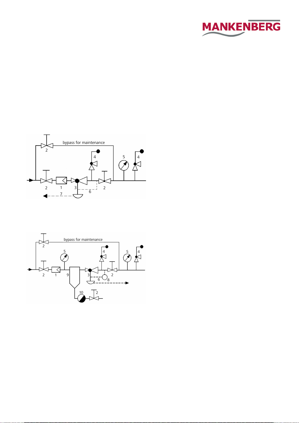
Recommended installation for liquids and gasses
1 Strainer 3 Pressure Reducer 6 Sense Line
or Filter 4 Safety Valve 7 Leakage Line
2 Shutoff Valves 5 Pressure Gauge
Sense Line Connection 10 - 20 x DN behind the valve
Recommended installation for steam
1 Strainer 5 Pressure Gauge 9 Water Trap
2 Shutoff Valves 6 Sense Line (Steam Dreyer)
3 Pressure Reducer 7 Leakage Line 10 Steam Trap
4 Safety Valves 8 Expansion Tank
Sense line connection 10 - 20 x DN behind the valve
Please consult our engineer if extreme operating conditions apply
or whenever you are in doubt.
Notes on Safety, Operating Instruction etc. MUST be followed.
2 / 2
Table of contents
Languages:
Other Mankenberg Industrial Equipment manuals


