manuals.online logo
Brands
  1. Home
  2. •
  3. Brands
  4. •
  5. Rexnord
  6. •
  7. Industrial Equipment
  8. •
  9. Rexnord Falk Freedom M20 Maintenance and service guide

Rexnord Falk Freedom M20 Maintenance and service guide

How To Use This Manual
This manual provides detailed instructions on installation,
annual maintenance and parts identification. Use the
following Table of Contents to locate required information.
Table of Contents
Introduction .....................Page1
Balanced Couplings .................Page1
General Assembly Information ............Page1
Installation ..................Pages 2 thru 3
Annual Maintenance .................Page3
Installation & Alignment Data .............Page4
Parts Identification ..................Page5
Order Information ..................Page5
CAREFULLY FOLLOW THE INSTRUCTIONS IN THIS
MANUAL FOR OPTIMUM PERFORMANCE AND TROUBLE
FREE SERVICE.
INTRODUCTION
This manual applies to standard free end float Falk Freedom
Disc Couplings which are normally used as the fourth bearing
in a three bearing system. These couplings will compensate for
only angular misalignment. When these couplings are used in
conjunction with a floating shaft, refer to Manuals 478-510 or
478-520 for proper instructions. For vertical or restricted
limited end float applications, refer to the Factory.
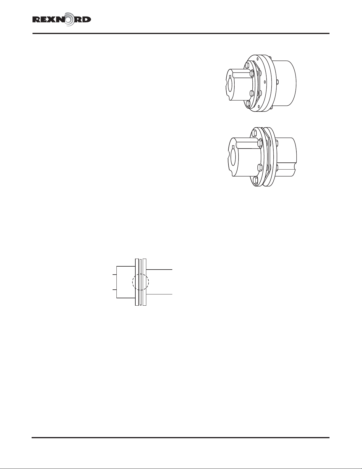
Balanced Couplings
The fasteners provided are matched sets and must not be
mixed or substituted. Assembly balanced couplings are match
marked and must be assembled
with mating match marks
aligned. Components parts of
assembly balanced couplings
must not be replaced without
re-balancing the complete
assembly. Some balanced
couplings may have the runout
etched at 90° intervals around
the flange O.D. Recheck runouts
after coupling is mounted. Any
wide variation in these readings must be corrected. Some
possible causes of variation are burrs on mating components
or bent shafts.
GENERAL ASSEMBLY INFORMATION
Standard mechanics tools, torque wrenches, a straight edge
and feeler gauges are required to install Falk Freedom Disc
Couplings. For best results use a dial indicator to check final
alignment and make certain bolts are tightened to the
required elongation or torque listed in Table 1 or 2. Outside
micrometer sizes required to measure drive bolt elongation
are listed in Table 1 or 2.
INTERFERENCE FIT HUBS — Unless otherwise specified,
Falk Freedom Disc Couplings are furnished for an
interference fit without set screw. Heat hubs to a maximum
275°F (135°C) using an oven, torch, induction heater or an
oil bath. DO NOT heat hubs beyond a maximum
temperature of 400°F (205°C).
When an oxy-acetylene or blow torch is used, use an excess
acetylene mixture. Mark hubs near the center of their length in
several places on hub body with a temperature sensitive
crayon, 275°F(135°C) melt temperature 400°F (205°C)
maximum to prevent over heating. Direct flame towards hub
bore using constant motion to avoid overheating an area.
WARNING: If on oil bath is used, the oil must have a flash
point of 350°F(177°C) or higher. Do not rest hubs on the
bottom of the container. Do not use an open flame in a
combustible atmosphere or near combustible materials.
Heat hubs as instructed above. Mount hubs as quickly as possible
with hub flange face flush with shaft end. Allow hubs to cool
before proceeding. Insert set screws (if required) and tighten.
CLEARANCE FIT HUBS — Clean all parts using a
non-flammable solvent. Check hubs, shafts and keyways for
burrs. Do not heat clearance fit hubs. Install keys, mount hubs
with flange face flush with shaft ends and tighten set screws.
Maximize Performance & Life
The performance and life of couplings depend largely upon
how you install and maintain them. Before installing
couplings, make certain that foundations of equipment to be
connected meet manufacturers’ requirements. Check for soft
foot. The use of stainless steel shims is recommended.
Measuring misalignment and positioning equipment within
alignment tolerances is simplified with an alignment computer.
These calculations can also be done graphically or
mathematically.
It is recommended that final alignment be checked using
either an alignment computer or graphical analysis. Both
methods allow the incorporation of “cold offsets”, which will
compensate for shaft position changes due to thermal growth.
WARNING: Consult applicable local and national safety
codes for proper guarding of rotating members. Observe all
safety rules when installing or servicing couplings. Lockout
starting switch of prime mover and remove all external loads
from drive before installing or servicing couplings.
Rexnord Industries, LLC, Coupling Group 478-150
5555 S. Moorland Rd., New Berlin, WI 53151-7953 USA Telephone: 262-796-4060 February 2001
Fax: 262-796-4064 e-mail: [email protected] web: www.rexnord.com Supersedes 9-90
Falk™ Freedom®Disc Couplings •Installation & Maintenance
Sizes 8 thru 8770 •Types M20 & N20 (Page 1 of 5)
Type M20
Type N20
A1
A1 MATCH
MARKS
INSTALLATION
1 — Mount Hubs
Lock out starting switch of prime mover. Check shafts, hub
bores and keyways for burrs or nicks. Make certain key slides
easily in shaft and hub keyways. (Note: Not all keys are
square. Certain bore conditions require rectangular keys and
these keys may be furnished with the coupling.) Mount hubs as
instructed on Page 1.
Proceed to Step 2 for Type N20 or Step 3 for Type M20.
2 — Type N20
A. Position equipment for approximate gap between shaft
ends per Table 1 with minimum angular misalignment.
Support single bearing shaft as necessary.
B. Install Discpacks — Rotate hubs on one end such that a
small flange hole of one hub is in line with a large flange
hole of the adjacent hub. Dip the threads and body
diameter of ALL main element bolts in SAE 30 or
equivalent oil. Starting at the top most small hole, insert
one main element bolt into the flange small hole of one of
the hubs. Note that the bolt head flats must contact the
hub diameter on some size couplings preventing bolt
rotation. Insert the discpack between flanges such that the
bolt engages the first discpack hole. Tap the bolt thru the
discpack hole and into the large hole of the adjacent hub.
Place an overload washer and locknut onto the bolt. DO
NOT TIGHTEN AT THIS TIME. Slowly swing the discpack
around this bolt between the flange faces aligning holes
with hub flange holes. Insert the remaining bolts thru the
small holes in both hub flanges. Install overload washers
and locknuts. DO NOT TIGHTEN AT THIS TIME. Check to
be sure bolt heads and locknuts alternate around the hub.
C. The most reliable method of tightening drive bolts is
achieved using Drive Bolt Elongation. Measure the length
of the #1 drive bolt with an outside micrometer and
record. Hold the drive bolt head and tighten the nut to the
tightening torque listed in Table 1. Re-check drive bolt
length. Subtract the first reading from the second reading.
Compare the difference to the elongation listed in Table
1. If required, increase or decrease tightening to achieve
the proper elongation. Repeat this procedure for each
drive bolt in cylinder head fashion as illustrated.
D. Proceed to Step 4.
3 — Type M20
A. Mount discpack and adapter to N-Hub.
1. Assembly balanced couplings will have the discpack
and adapter already assembled. Proceed to Step A2 if
couplings are not assembly balanced. Install overload
washers onto the remaining main element bolts. Dip
the threads in SAE 30 or equivalent oil and insert into
large adapter holes and thru remaining holes in
discpack. Mount assembly to small holes in N-Hub.
Install nuts until bolt protrudes through nut. DO NOT
FULLY TIGHTEN. Proceed to Step A4.
2. Install overload washers onto half of the main element
bolts. Dip the threads of all bolts in SAE 30 or
equivalent oil. Insert drive bolts with overload washers
through alternate holes in one discpack and through
the small holes in the N-Hub. Install nuts until bolts
protrude through nut. DO NOT FULLY TIGHTEN.
3. Insert the remaining drive bolts from the counterbore
side of the adapter through the three small
non-threaded holes and through the remaining holes in
the discpack. These bolts should now be protruding
through the large holes in the flange of the N-Hub.
Install the remaining overload washers and nuts onto
these bolts. All nuts must be on the N-Hub side and all
bolt heads located in the adapter.
4. The most reliable method of tightening drive bolts is
achieved using Drive Bolt Elongation. Measure the
length of the #1 drive bolt with an outside micrometer
and record. Hold the drive bolt nut and tighten the bolt
to the tightening torque listed in Table 2. Recheck drive
bolt length. Subtract the first reading from the second
reading. Compare the difference to the elongation
listed in Table 2. If required, increase or decrease
tightening to achieve proper elongation. Repeat this
procedure for each drive bolt in cylinder head fashion
as illustrated below.
Rexnord Industries, LLC, Coupling Group478-150
5555 S. Moorland Rd., New Berlin, WI 53151-7953 USA Telephone: 262-796-4060February 2001
Fax: 262-796-4064 e-mail: [email protected] web: www.rexnord.comSupersedes 9-90
Installation & Maintenance •Falk™ Freedom®Disc Couplings
(Page 2 of 5) Types M20 & N20 •Sizes 8 thru 8770
5
3
2
6
4
8
1
3
2
4
1
1
4
2
5
3
6
DRIVE BOLT TIGHTENING PATTERN
4-BOLT 6-BOLT 8-BOLT
5
3
7
2
6
4
8
1
1
4
2
5
3
6
DRIVE BOLT TIGHTENING PATTERN
6-BOLT 8-BOLT
B. Position equipment for approximate gap between N-Hub
and adapter per Table 2 with minimum angular
misalignment being sure to engage female pilot of
adapter onto male pilot of A-Hub.
C. Dip adapter bolts in SAE 30 or equivalent oil and place
lock washers on bolts. Install adapter bolts with lock
washers thru A-Hub flange holes and engage tapped
holes in adapter. Tighten adapter bolts to recommended
torque as given in Table 2 being sure male-female pilot is
properly engaged.
D. Proceed to Step 4.
4 — Check Angular Alignment
A. Position equipment axially to obtain proper gap as given
inTable1or2.
B. Take readings with a spacer block and feeler gages at 90°
intervals between flange faces. If a dial indicator is used,
attach it to one shaft and rotate assembly 360° while
taking readings on the flange face as shown. Do not
exceed INSTALLATION ANGULAR limit specified in Table
1or2.
C. Tighten foundation bolts, recheck alignment and correct
if necessary.
CAUTION: Dial indicator face readings should not to be used
on journal or sleeve bearing equipment due to the liberal end
float inherent in such a design.
ANNUAL MAINTENANCE
For extreme or unusual operating conditions, check coupling
more frequently.
1. Check alignment per Step 4, Page 3. If operation limits
from Tables 1 or 2 are exceeded, re-align coupling to
installation limits.
2. Check outer blades of discpacks near bushings for fatigue
cracks. Discpacks can be checked while coupling is in
operation by using a strobe light. Replace cracked
discpacks and recheck alignment. A slight bowing or “S”
like distortion is normal.
3. Check tightening torques of all drive bolts.
Rexnord Industries, LLC, Coupling Group 478-150
5555 S. Moorland Rd., New Berlin, WI 53151-7953 USA Telephone: 262-796-4060 February 2001
Fax: 262-796-4064 e-mail: [email protected] web: www.rexnord.com Supersedes 9-90
Falk™ Freedom®Disc Couplings •Installation & Maintenance
Sizes 8 thru 8770 •Types M20 & N20 (Page 3 of 5)
TYPE M20TYPE N20
GAP
GAP
Rexnord Industries, LLC, Coupling Group478-150
5555 S. Moorland Rd., New Berlin, WI 53151-7953 USA Telephone: 262-796-4060February 2001
Fax: 262-796-4064 e-mail: [email protected] web: www.rexnord.comSupersedes 9-90
Installation & Maintenance •Falk™ Freedom®Disc Couplings
(Page 4 of 5) Types M20 & N20 •Sizes 8 thru 8770
TABLE 2 — Installation & Alignment Data – Type M20 – Dimensions Inches
SIZE Gap
Gap
Tolerance
+
Alignment
Axial †
Float
Max +
Adpt. Bolt
Tightening
Torque
lb-ft Oiled
Drive Bolt
Tightening
Torque
lb-ft Oiled
Drive Bolt
Elongation
Outside
Micrometer
Size — in
Installation Operation —
Max
Angular H(TIR)
Max-Min
Angular H(TIR)
Max-Min
85 .405 .008 .015 .030 .053 6.7 21 .0025-.0030 1-2
190 .495 .008 .017 .034 .060 6.7 54 .0035-.0045 1-2
340 .525 .008 .020 .040 .069 15.7 84 .0035-.0045 2-3
625 .600 .008 .022 .044 .075 28 169 .0050-.0060 2-3
1080 .675 .008 .026 .052 .080 74 289 .0060-.0070 3-4
1700 .750 .008 .030 .060 .106 74 460 .0065-.0075 3-4
2500 .895 .008 .023 .046 .085 137 466 .0070-.0080 3-4
3160 .851 .008 .025 .050 .098 137 466 .0065-.0075 4-5
4630 .851 .008 .028 .056 .115 237 688 .0065-.0075 4-5
6470 1.060 .008 .031 .062 .121 137 973 .0090-.0100 5-6
8770 1.095 .008 .034 .068 .127 137 1333 .0110-.0120 5-6
HGAP maximum minus GAP minimum. TIR = Total Indicator Reading.
†Values are without misalignment.
TABLE 1 — Installation & Alignment Data – Type N20 – Dimensions Inches
SIZE Gap
Gap
Tolerance
+
Alignment
Axial †
Float
Max +
Drive Bolt
Tightening
Torque
lb-ft Oiled
Drive Bolt
Elongation
Outside
Micrometer
Size — in
Installation Operation — Max
Angular H(TIR)
Max-Min
Angular H(TIR)
Max-Min
8.260 .010 .014 .028 .053 4.2 .0025-.0030 1-2
23 .350 .010 .018 .036 .071 11.8 .0035-.0040 1-2
43 .401 .010 .021 .042 .083 21 .0040-.0045 1-2
85 .405 .008 .015 .030 .053 21 .0025-.0030 1-2
190 .495 .008 .017 .034 .060 54 .0035-.0045 1-2
340 .525 .008 .020 .040 .069 84 .0035-.0045 2-3
625 .600 .008 .022 .044 .075 169 .0050-.0060 2-3
1080 .675 .008 .026 .052 .080 289 .0060-.0070 3-4
1700 .750 .008 .030 .060 .106 460 .0065-.0075 3-4
2500 .895 .008 .023 .046 .085 466 .0070-.0080 3-4
3160 .851 .008 .025 .050 .098 466 .0065-.0075 4-5
4630 .851 .008 .028 .056 .115 688 .0065-.0075 4-5
6470 1.060 .008 .031 .062 .121 973 .0090-.0100 5-6
8770 1.095 .008 .034 .068 .127 1333 .0110-.0120 5-6
HGAP maximum minus GAP minimum. TIR = Total Indicator Reading.
†Values are without misalignment.
PARTS IDENTIFICATION
All coupling parts have identifying part numbers. When ordering
parts, always specify SIZE and TYPE shown on the hub and the
part number on the discpack & adapter. For special couplings,
furnish M.O. Number and drawing number stamped on the
coupling & adapter. The decimal bore size is stamped on the
hub face opposite the flange.
PART NUMBER LOCATIONS
ORDER INFORMATION
1. Identify part(s) required.
2. Furnish the following information:
Example:
Coupling Size: 85
Type: M20
Hub Type: AorN
Bore: 3.250 A-Hub
Keyway: .750 X .375
Bore: 2.250 N-Hub
Keyway: .500 x .250
Discpacks: Coupling Size
Adapter: Part Number
3. Price parts from appropriate Price List and Discount
Sheet.
SPECIAL COUPLINGS: For special couplings furnish SIZE
and TYPE shown on the hub, M.O. Number, drawing
numbers on the hubs and adapter.
Rexnord Industries, LLC, Coupling Group 478-150
5555 S. Moorland Rd., New Berlin, WI 53151-7953 USA Telephone: 262-796-4060 February 2001
Fax: 262-796-4064 e-mail: [email protected] web: www.rexnord.com Supersedes 9-90
Falk™ Freedom®Disc Couplings •Installation & Maintenance
Sizes 8 thru 8770 •Types M20 & N20 (Page 5 of 5)
LOCK NUT
OVERLOAD
WASHER
DRIVE BOLT
LOCK
WASHER
ADAPTER BOLT
A-HUB (SPECIFY BORE
&KEYWAY)
DRIVE
BOLT OVERLOAD WASHER
ADAPTER
DISCPACK LOCK
NUT N-HUB (SPECIFY BORE
&KEYWAY)
N-HUB
BORE
DRAWING
NUMBER
M.O.
NUMBER
(SPECIALS)
85FD06N
ADAPTER
DISCPACK
PART
NUMBER
705500
1227025
PRODUCT
CLASSIFICATION
DRAWING
NUMBER
BORE
A-HUB
COUPLING
SIZE HUB TYPE
NUMBER OF
DRIVE BOLTS
85 FD 06 A
M.O.
NUMBER
(SPECIALS)
8-908795
1227013-3
85FD06A
3.250

This manual suits for next models

1

Other Rexnord Industrial Equipment manuals

Rexnord Falk GL20 Instruction Manual

Rexnord

Rexnord Falk GL20 Instruction Manual

Rexnord Falk NRT Use and care manual

Rexnord

Rexnord Falk NRT Use and care manual

Rexnord Falk Lifelign G66 User manual

Rexnord

Rexnord Falk Lifelign G66 User manual

Rexnord Falk SteelfIex T10 Series Maintenance and service guide

Rexnord

Rexnord Falk SteelfIex T10 Series Maintenance and service guide

Rexnord SURE-flex User manual

Rexnord

Rexnord SURE-flex User manual

Rexnord Hansen TRANSMISSION PENCOflex User manual

Rexnord

Rexnord Hansen TRANSMISSION PENCOflex User manual

Rexnord Falk  Steelflex T10 Maintenance and service guide

Rexnord

Rexnord Falk Steelflex T10 Maintenance and service guide

Rexnord Thomas XTSR52 Instruction Manual

Rexnord

Rexnord Thomas XTSR52 Instruction Manual

Rexnord Falk GC02 Instruction Manual

Rexnord

Rexnord Falk GC02 Instruction Manual

Rexnord Falk NRTH B 1055 Maintenance and service guide

Rexnord

Rexnord Falk NRTH B 1055 Maintenance and service guide

Rexnord Falk GL32 Maintenance and service guide

Rexnord

Rexnord Falk GL32 Maintenance and service guide

Rexnord Stearns 1-081-X00 Series User manual

Rexnord

Rexnord Stearns 1-081-X00 Series User manual

Rexnord AUTOGARD 400 Series User manual

Rexnord

Rexnord AUTOGARD 400 Series User manual

Rexnord DTS-C 2000 Installation and operation manual

Rexnord

Rexnord DTS-C 2000 Installation and operation manual

Rexnord FALK HF132 Maintenance and service guide

Rexnord

Rexnord FALK HF132 Maintenance and service guide

Rexnord Falk  Steelflex T10 User manual

Rexnord

Rexnord Falk Steelflex T10 User manual

Rexnord Hydro-flow Series User manual

Rexnord

Rexnord Hydro-flow Series User manual

Rexnord Falk MCF 1135 Maintenance and service guide

Rexnord

Rexnord Falk MCF 1135 Maintenance and service guide

Rexnord Falk NRT E 70 User manual

Rexnord

Rexnord Falk NRT E 70 User manual

Rexnord Thomas Tpack 52 Series Instruction Manual

Rexnord

Rexnord Thomas Tpack 52 Series Instruction Manual

Popular Industrial Equipment manuals by other brands

Buchi Rotavapor R-220 EX Operation manual

Buchi

Buchi Rotavapor R-220 EX Operation manual

LMI Technologies MikroCAD quick start guide

LMI Technologies

LMI Technologies MikroCAD quick start guide

IEMCA BOSS 542 CNC Manual for use and maintenance

IEMCA

IEMCA BOSS 542 CNC Manual for use and maintenance

ABB PT003924 Operation manual

ABB

ABB PT003924 Operation manual

PPI STATIC SHAFT PULLEY Operation & maintenance manual

PPI

PPI STATIC SHAFT PULLEY Operation & maintenance manual

Hubbell Walltrak PW2FEBC installation instructions

Hubbell

Hubbell Walltrak PW2FEBC installation instructions

Phoenix Contact IL PB BK DI8 DO4/EF-PAC user manual

Phoenix Contact

Phoenix Contact IL PB BK DI8 DO4/EF-PAC user manual

ABB XAC25395 Operation manual

ABB

ABB XAC25395 Operation manual

ABB XAC25926 Operation manual

ABB

ABB XAC25926 Operation manual

R.V.R. Elettronica PJ5KPS User's & technical manual

R.V.R. Elettronica

R.V.R. Elettronica PJ5KPS User's & technical manual

Huawei SUN2000-4.95KTL-JPL0 user manual

Huawei

Huawei SUN2000-4.95KTL-JPL0 user manual

Schulze BLUEpress instruction manual

Schulze

Schulze BLUEpress instruction manual

probst SG-80-PGL2 operating instructions

probst

probst SG-80-PGL2 operating instructions

Giacomini GE551Y194 quick start guide

Giacomini

Giacomini GE551Y194 quick start guide

Viega Geopress K Instructions for use

Viega

Viega Geopress K Instructions for use

Doyon KDP Series installation manual

Doyon

Doyon KDP Series installation manual

TE Connectivity 1871696-1 instruction sheet

TE Connectivity

TE Connectivity 1871696-1 instruction sheet

3M Attest 390 Operator's manual

3M

3M Attest 390 Operator's manual

manuals.online logo
manuals.online logoBrands
  • About & Mission
  • Contact us
  • Privacy Policy
  • Terms and Conditions

Copyright 2025 Manuals.Online. All Rights Reserved.