Nordco LS-C User manual

MODEL “LS-C”
63" WIDE GAUGE AUtO-LIft
Operation and
Maintenance
Manual
Applies to S/N 7901000 and Above
Reorder Part: 49457901
Last Revision: Rev. -
MARCH 2012


This manual is a guide for the operation and routine maintenance of a NORDCO Railroad Maintenance
Machine. It covers product technical information, basic operating and maintenance procedures, and
safety information and is provided for use by the qualified personnel who will supervise, operate or service
the equipment described herein.
Measurements in this manual are given in both metric and customary U.S. unit equivalents.
Personnel responsible for the operation and maintenance of this equipment should thoroughly study the
manual before commencing operation or maintenance procedures.
This manual should be considered a permanent part of your machine and should
remain with the machine at all times.
Additional copies of this manual are available either as a part (Operation Manual
only) or a whole (operation and parts manual), at a nominal cost, through our Part
Sales Department. Additional service information, parts, and application information
is available through these Nordco product support resources:
NORDCO Sales: Milwaukee, Wisconsin
(414) 766-2180
sales@nordco.com
NORDCO Parts: Milwaukee, Wisconsin
1-800-647-1724
parts@nordco.com
NORDCO Service: 1-800-445-9258
service@nordco.com
We ask that if you have any comments or suggestions about this manual, let us hear from you. We are
here to be of service to you, our customers. Direct your comments and inquiries to:
Technical Documentation Department
NORDCO Inc.
245 W. Forest Hill Avenue
Oak Creek, WI 53154

HAZARDOUS MATERIAL DATA
In an effort to provide information necessary for your employee safety training program and to meet the
requirements of OSHA Hazard Communication Standard 1910.1200, we have OSHA Form 20 Safety Data
Sheets available that cover the material contained in this machine.
If you are interested in receiving this information, please refer to the Name, model, and Serial Number of
your machine when calling or writing, and direct your inquiries to:
Vice-President of Operations
NORDCO Inc.
245 W. Forest Hill Avenue
Oak Creek, WI 53154
Fax: (414) 766-2299
Phone: (414) 766-2288

Autolift Model LS-C SAFETY
SEPT/2004 (4945-7900) Section 1-1
SAFETY
Please read and comply with all of the
safety precautions in this manual BEFORE
operating this machine.
GENERAL
DO NOT use this machine for machine
operations other than for which it was
intended.
NORDCO is not responsible for any
modifications made without authorization or
written approval. Replace all NORDCO
and OEM parts with genuine NORDCO or
OEM parts. Use of non-OEM parts could
compromise the safety of your machine.
FRA regulations require that a copy of this
Operation Manual be kept on the machine
at all times. Additional copies of the
Operation Manual only can be ordered
from Nordco Parts Sales at 1-800-647-
1724.
FOLLOW SAFETY INSTRUCTIONS
Carefully read all safety messages in this
manual. Learn how to operate the
machine and how to use controls properly.
Do not let anyone operate this machine
without instruction. Failure to understand
the contents of this manual could result in
serious personal injury or death.
SAFETY ALERT SYMBOLS!
These are the safety-alert symbols.
These symbols means pay
attention! Your safety is at risk!
DANGER is used to indicate a definite
hazardous situation which, if not avoided,
WILL result in severe bodily harm or even
death.
WARNING indicates a potentially
hazardous situation which, if not avoided,
COULD result in severe bodily harm or
even death.
CAUTION indicates a potentially
hazardous situation which, if not avoided,
MAY result in minor or moderate injury.
CAUTION without the safety “!” means that
failure to follow the alert may result in
machine damage.
SAFETY means that the following points
are instructions for safely operating the
machine or the specific component of the
machine.

SAFETY Autolift Model LS-C
Section 1-2 SEPT/2004 (4945-7900)
GENERAL SAFETY TIPS
Only trained and authorized personnel
should be allowed to operate this machine.
In addition, all personnel at the worksite
(gang) should be aware of the safety
concerns and their individual
responsibilities prior to working this
machine.
1. Handle fuel safely. It is highly
flammable and prolonged
breathing of fumes may cause
bodily harm.
2. Prepare for emergencies. Keep a
first aid kit and fire extinguisher
handy.
3. Protect against flying pieces of
metal and debris by wearing safety
glasses or goggles.
4. Wear good-fitting pants and shirt,
no baggy or loose clothing.
5. Protect your head and eyes from
flying debris by wearing a hard hat
and safety goggles/glasses.
6. Wear leather gloves to protect your
hands from vibration or flying metal
particles.
7. Use safety-toed work boots.
SAFETY PRIOR TO WORKING
All personnel at the worksite (gang) should
be aware of the safety concerns and their
individual responsibilities prior to working
this machine:
• Review the operating instructions if
you are unsure of anything.
• Use the “pre-operational checklist”
to check the machine for obvious
faults. Repair or replace as
necessary PRIOR to operating the
machine.
• Before climbing onto the machine,
make certain the area around and
under the machine is clear of
obstructions and personnel.
• Use care when climbing onto the
machine. Always use the steps
and handrails provided. (If an area
does not have tread grips,
walkways, or other methods to
access the area, then DO NOT
attempt to access that area.)
• Make seat and control adjustments
PRIOR to starting the machine.
ALWAYS wear a seatbelt.
• Know the weather forecast and
plan your work speeds accordingly.
• There are guards on this machine.
These are to be removed ONLY
when service or maintenance is
being performed on that area of
the machine. Make certain they
have been re-installed PRIOR to
starting the machine.
• Check and service the fire
extinguisher (if so provided) at
regular intervals. Make certain all
personnel are trained in its use.
Note - Non-use of fire extinguisher
still requires that it be recharged at
the interval stated on its last
inspection notice.
• Keep the stairs, cab entry platform
and cab interior free and clear of
ice, tools and personal items. Use
the accessories provided on the
machine (tool box, cup holder, coat
hook, etc.) to properly store your
gear.
• Never climb onto the machine
while it is in motion.
• There are lockups on this machine
that are used for both work and
travel. These should be kept clear
and free of debris, grease, etc.
See Lockup section for
instructions on their use.
• Inspect safety decals and replace
when they become unreadable or
are damaged. (See “Safety
Decals”at the end of this Safety
section).

Autolift Model LS-C SAFETY
SEPT/2004 (4945-7900) Section 1-3
SAFETY WHILE STARTING THE
MACHINE
NORDCO recommends the use of a
Command position. This means that the
machine is never running unless someone
is at or near the main control panel or
remote control boxes. To prevent injury to
personnel or damage to the machine, it is
highly recommended to:
1. Only start and operate the machine
from the operator’s seat.
2. Use the “STARTUP Checklist” to
check the machine controls and
gauges to make certain all systems
are operating correctly.
SAFETY WHILE
OPERATING/TRAVELING
1. Never allow more riders than seats and
seatbelts allow. This machine was
designed to be operated by one
person.
2. The machine is to be operated from
the Operator’s seat only. Do NOT
stand and operate this machine.
3. Press the EMERGENCY STOP
pushbutton on the center control
console in emergencies and potentially
dangerous situations.
4. If personnel or bystanders are near the
machine during operation, give a
warning signal using the air horn. If
they fail to respond to this warning,
stop operation immediately.
5. Slow down the work cycle and use
slower travel speeds in congested or
populated areas.
6. Halt work if visibility is poor. Strong
rains, fog, and extremely dusty
conditions can affect visibility in your
work area. Wait for the weather to
improve before continuining work.
SAFETY WHILE PARKED
When leaving a machine engine running,
make certain that the parking brake is
applied and the electrical interlock button
has been activated.
NEVER stop and park this machine on an
incline unless the machine wheels have
been chocked.
SAFETY DURING MAINTENANCE
The following guidelines are suggested
when performing maintenance:
1. Always chock the wheels
2. Alert others in the area that service
or maintenance is being performed
on this machine.
3. Become familiar with, and use,
your company’s lockout/tagout
procedures when performing
maintenance on this machine. See
LOCKOUT/TAGOUT
REQUIREMENTS later in this
Safety Section for a chart on
energy sources located on this
machine.
4. Do not start the engine if repairs or
work is being performed alone.
You should always have at least
two people working together if the
engine must be run during service.
One person needs to remain in
the command position (at the
controls), ready to stop the
machine and shut off engine if the
need arises.
5. Collect oils and fuels and dispose
of them properly. There is a
danger of scalding when working
with engine oils.
6. Use only Nordco supplied repair
parts for this machine. Use of non-
OEM designed parts could
comprise the integrity of this
machine.
7. There are welding cautions on this
machine. Pay attention to them
PRIOR to welding.
8. Kits supplied by Nordco have
welding instructions included.
Welding of any components NOT
of Nordco’s manufacture or failure
to follow these instructions may
affect the stability of this machine.

SAFETY Autolift Model LS-C
Section 1-4 SEPT/2004 (4945-7900)
MACHINE SAFETY
ALERTS
DANGER ALERTS
Improper use of this machine for
any type of operation can cause
serious injury or death.
To avoid serious injury or death,
make certain that the area around
and under the machine is clear of
all personnel and obstructions
BEFORE travelling or working.
Serious injury or death can result
from reaching into working
components while machine is
running. Make all observations
from a distance and SHUT OFF
machine while making adjustments.
Shut off engine when checking
battery electrolyte level. Do not
check or fill battery in presence of
open flame, sparks, or when
smoking. Battery fumes are
flammable and/or explosive and if
ignited will result in severe bodily
injury or death.
Do not ride on tow bar between the
machine and the towing vehicle.
Falling from a moving vehicle may
cause serious injury or death.
Never Ride on This Machine.
MACHINE SAFETY
ALERTS
WARNING ALERTS
Failure to engage all lockup devices
before propelling at travel speed
can result in injury to personnel
and/or extensive damage to the
machine.
Remove hoses/fittings only when
system is not pressurized. High
pressure leaks can cause personal
injury.
Always turn off machine when
performing maintenance, making
adjustments, or whenever
unintended movement of machine
could occur; unless directed
otherwise. Failure to comply could
result in personal injury and/or
damage to the machine.
Exhaust emissions caused by the
use of the engine on this machine
may cause cancer, birth defects, or
other reproductive harm if inhaled.
Disconnect the battery before
servicing this machine. Failure to
do so could result in personal injury
from accidental engine startup.

Autolift Model LS-C SAFETY
SEPT/2004 (4945-7900) Section 1-5
LOCKOUT AND/OR TAGOUT
REQUIREMENTS
The following list suggests lockout
procedures to use on all components
of the machine that require lockout due
to the storage of various forms of
energy. It is your company’s
responsibility to Lockout/Tagout
Procedures based on this list, train
you in their proper and safe use, and to
periodically inspect your work area to
verify that you are complying with the
procedures. Lockout/Tagout
Procedures must be followed!
NORDCO has provided the means to
lockout this machine. NORDCO
cannot be held responsible for injury
caused by failure to comply with your
company’s Lockout/Tagout
Procedures. See next page for
suggested lockout/tagout procedure
list.

SAFETY Autolift Model LS-C
Section 1-6 SEPT/2004 (4945-7900)
LOCKOUT-TAGOUT PROCEDURES
The following procedures are designed to lead the operator through the steps required to shut the
machine down and prepare it for performing mechanical maintenance work. These procedures are
intended to release potentially dangerous stored energy forms and make the machine safe to begin
repairs.
SAFETY PROCEDURES
LOCKOUT/TAGOUT
1. Apply Parking Brake.
2. Chock wheels to prevent accidental rolling of machine on grade.
3. If you have not already done so, determine which components
are to have maintenance. Place all machine mechanical systems
or workheads in the full up and locked positions.
4. Refer to the list at the bottom of the page to determine what
procedures are required when mechanical locking up of
equipment is not feasible for maintenance. Then continue on
with Steps 5-8.
5. Turn the ignition switch to the OFF position. This turns off the
power to the control circuits on the machine. Place a TAGOUT
card in close proximity to the ignition switch.
6. Turn the battery disconnect switch (BDS) to the OFF position.
a. For machines with the BDS on the left side of the center
(front) control console: Place a TAGOUT card on the
switch after you have switched it to the OFF position.
b. For machines with a remotely located BDS (usually next
to the battery box itself): Close the cover to the
disconnect switch and place a LOCKOUT lock on the
box after you have switched it to the OFF position.
7. Bleed off hydraulic pressure.
8. Follow all of your company’s lockout/tagout rules before
proceeding. Note: When working on machine components, be
aware that moving components during repairs may create
energy (ie., moving a hydraulic cylinder). Proper precautions
should be taken.
This list is for specific components in an assembly, where maintenance cannot be performed with
the assembly in the full up and/or locked position. After completing the steps required, continue on
with Steps 5-8 above.
When performing maintenance on: Secure as follows:
RAIL CLAMP ASSEMBLY
Rail Lift Up/Down Cylinder Lower Rail Clamp Assembly to rail.
Rail Clamp In/Out Cylinder Lower Rail Clamp Assembly to rail and
place a support under the rail clamp lever.

Autolift Model LS-C SAFETY
SEPT/2004 (4945-7900) Section 1-7
SAFETY DECALS ON THIS MACHINE
Safety decals and plaques that have been placed on this machine are to be kept clean and legible.
Replace any decals or plaques that have become illegible or are missing.
When repairing or replacing components that had safety decals on them, it is your responsibility to
replace the safety decals. These can be ordered from the Parts Sales Department.
Safety Decals on this Machine are:
PART NO. DESCRIPTION LOCATION
5642 0002 Caution! Watch Your Step Frame, by Step
5642 0004 Danger! Pinch Points On Rail Clamps
5642 0005 Warning! Hand Hazard On Rail Clamps
5642 0006 Danger! Before Servicing... Logic Box Sides
5642 4501 Caution! Before Welding... Logic Box Face
Battery Box
5642 0010 Lockout Area Logic Box Face
5642 0011 Lockout Area Battery Box
5642 0012 Lockup Points All areas requiring
Lockups for travel.

SAFETY Autolift Model LS-C
Section 1-8 SEPT/2004 (4945-7900)
This page intentionally left blank

Auto-Lift Model “LS-C” GENERAL
Section 1-9 SEPT/2004 (4945-7900)
GENERAL
This manual contains operation and maintenance information for the MODEL “LS-C” AUTO-LIFT
manufactured by NORDCO INC., Oak Creek, Wisconsin. Information regarding the operation and
maintenance of this machine can be found behind the appropriate tabs. Information regarding operation and
maintenance of OEM parts not of NORDCO manufacture can be found at the back of this manual, behind the
tab marked Component Data.
Become familiar with all safety instructions, controls and instruments before operating this machine. Follow all
instructions carefully.
ABOUT THIS MANUAL
This manual has been broken down into sections which have been separated by index tabs:
This manual has been broken down into sections which have been separated by index tabs:
Mechanical has individual parts breakdown drawings and lists for each assembly
Hydraulic includes adjustment instructions and troubleshooting for the hydraulic system; and all piping
and functional drawings for a standard machine and optional equipment
Electrical, includes all electrical schematics, logic box, control box, and cable drawings for the machine;
and troubleshooting instructions
Component Data includes parts breakdowns and service instructions for components installed on the
machine that are not of NORDCO’s manufacture

Auto-Lift Model “LS-C” GENERAL
Section 1-10 SEPT/2004 (4945-7900)
SPECIFICATIONS
GENERAL
Model..................................................................................................................................................Model LS-C
Gross Weight*.......................................................................................................................................... 4000 lbs
Length.................................................................................................................................................... 92 inches
Width...................................................................................................................................................... 72 inches
Height
Hatz Engine .........................................................................................................................................97 inches
Deutz Engine ............................................................................................................Not Available at This Time
Wheel Base.............................................................................................................................................50 inches
Working Clearance (from center of track).....................................................................................5 feet 10 inches
Travel Speed (Variable)...............................................................................................................................4 mph
CAPACITIES
Fuel Tank (Painted Green) ...............................................................10 gallons (Standard), 18 gallons (Optional)
Hydraulic Oil Tank (Painted Blue)........................................................................................ 30 gallons (standard)
Plate Storage.............................................................................................................................35 plates on deck
ENGINE
Make/Model ........................................................................................................................................Hatz 2M41Z
Type...........................................................................................................4 Cycle, 2 Cylinder, Air Cooled Diesel
Continuous BHP ................................................................................................23 HP @ 2050 RPM, Under load
Low Idle/High Idle ...................................................................................................................1150 rpm/2140 rpm
HYDRAULIC SYSTEM (MANIFOLDED)
Pump Make/Model........................................................................................................................Parker PAVC65
Type...................................................................................................................................................Piston Pump
Rating....................................................................................................................................23 gpm @ 2050 rpm
Relief Valve Setting (High System Pressure)...........................................................................................3000 psi
System Pressure.......................................................................................................................................2400 psi
ELECTRICAL SYSTEM
Battery.............................................................................................................12 Vdc, 1150 Cold Cranking Amps
Ground.....................................................................................................................................................Negative
Alternator ...................................................................................................................................................50 Amp
DRIVE SYSTEM
Drive Type...........................................................................................................................Dual Axle Chain Drive
Axle Type...............................................................................................................................................Stationary
Clutch Type...................................................................................................................................Lever Activated
Propulsion Motor Type............................................................................................................................Hydraulic
WHEELS
Type.......................................................................................................................................................Cast Steel
Size..............................................................................................................................................14 inch diameter
Items or capacities may vary according to options on your machine.
* Approximate weight. Actual weight may vary according to options on your machine. Actual weight of your
machine is as stenciled.
All rights reserved. In view of the constant improvements to our equipment, the specification data and other
technical information included in this manual are subject to change. No part of this manual may be
reproduced in any form or by any means without our written permission.
Auto-Lift Model “LS-C” OPERATION
SEPT/2004 (4945-7900) Section 2-1
Before operating this machine, read and
understand the Safety Section of this Manual.
BEFORE OPERATION
It is always good practice to become totally familiar
with the machines you are going to operate.
IMPROPER USE OF THIS MACHINE FOR
ANY TYPE OF OPERATION CAN CAUSE
SERIOUS INJURY OR DEATH.
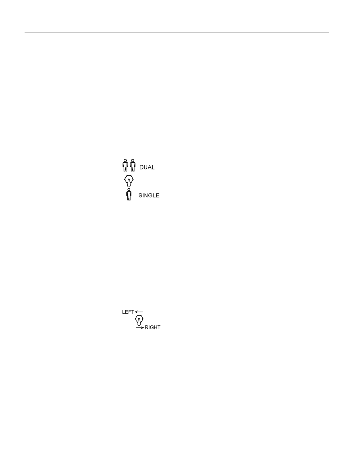
BASIC DESCRIPTION
This machine can be run by
either one or two operators.
When DUAL Operation is
selected, two operators walk
alongside the machine and are
both required to actuate the
propel switch at the same time to
move the machine. This is done
so that the machine cannot be accidently
moved before the second operator has finished
working. When they have spotted the machine
over the rail section to be lifted, they release the
propel switch, press the cycle start button, and the
machine begins the work cycle. The work cycle is
as follows: first, the clamps come down and grasp
the rail; next, the lift cylinders come down and lift
the machine (and rail) to a predetermined height.
After the tie plate has been positioned under the
rail, both operators again depress the propel
switch; the lift cylinder retracts lowering the
machine. Then after the rail clamps open,
releasing the rail, the operators propel the machine
to the next tie and prepare to begin another cycle.
When SINGLE Operation is
selected, the operator must
select which side of the rail he or
she will be working. The side of
the machine that is active is
determined while standing at the logic box.
THIS MACHINE IS NOT EQUIPPED WITH
SEATS OR SEATBELTS. DO NOT RIDE
ON OR ALLOW OTHERS TO RIDE ON THIS
MACHINE WHEN WORKING, TRAVELLING,
OR TOWING. FAILURE TO COMPLY
COULD RESULT IN SEVERE PERSONAL
INJURY OR DEATH.
This machine is not designed for passengers
during work or travel operations. There are no
seats or seatbelts provided on this machine. DO
NOT RIDE ON THIS MACHINE!
HYDRAULIC SYSTEM
The Model “LS-C” hydraulic system uses a series
of manifolds. More detailed information regarding
the hydraulic system and manifolds is located
behind the tab marked “HYDRAULICS”.
The hydraulic pump is a pressure compensated,
variable displacement, radial piston type,
providing high flow and pressure. Refer to the
preface of the Hydraulic Section of this manual for
more information on the hydraulic system and it’s
adjustments.
LOGIC BOX CONTROL PANEL
The logic box control panel houses nearly all of the
operator selectable items on the machine, with the
exception of the remote operator control boxes.
The logic box drawing on the next page is
representative of a standard machine. Become
familiar with its functions.
REMOTE OPERATOR CONTROL BOXES
There are two operator stations, one on each side
of the machine. At these stations are the remote
operator control boxes, which control the work
cycle and propulsion of the machine. (See Figure
below.)
PLATE PUSHER
This assembly allows the operator to run the
controls of the machine without having to stand
next to the remote control boxes described above.
The identical controls are on the plate pusher
assembly.
OPERATION Auto-Lift Model “LS-C”
Section 2-2 SEPT/2004 (4945-7900)
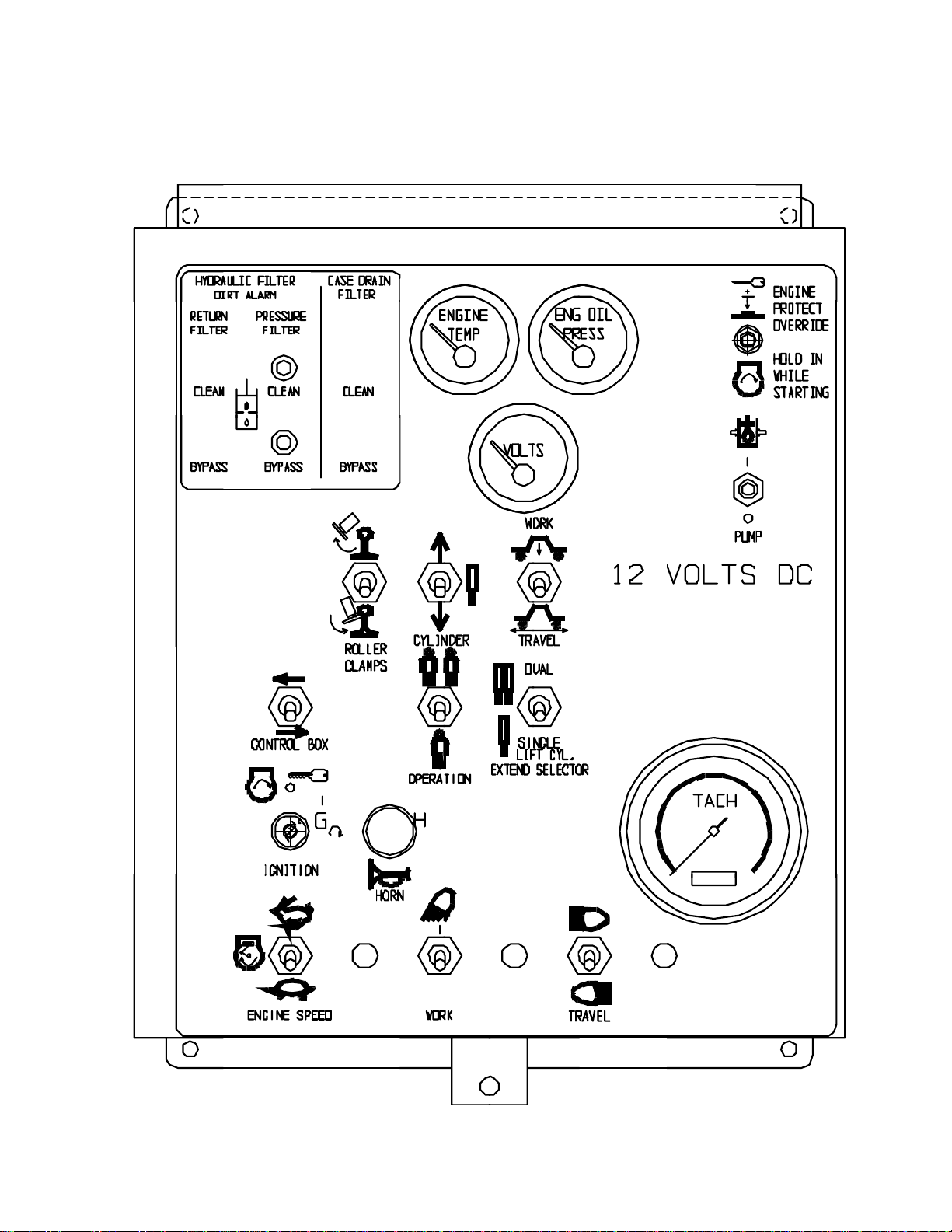
MAIN CONTROL PANEL
(LOGIC BOX)
Auto-Lift Model “LS-C” OPERATION
JULY/2004 (4945-7900) Section 2-3
MAIN CONTROL PANEL
ENGINE AND PUMP CONTROLS AND GAUGES
(Includes Horns and Lights)
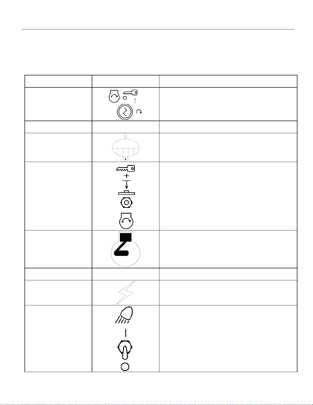
CONTROL OR
INSTRUMENT INTERNATIONAL
SYMBOL
FUNCTION
Key Switch
The electrical system is energized by turning the key to the
right. Electrical power is cut off and the engine will stop
when the key is turned to the full left or vertical (OFF)
position.
Engine OIL PRESSURE
Gauge Indicates oil pressure, not oil level. Normal reading is 60-
80 psi.
Engine OIL
TEMPERATURE Gauge
Indicates engine oil temperature measurement. Normal
operating temperature is between 170 and 280 degrees F
(76 and 110 degrees Celcius)
MAGNETIC OVERRIDE
Switch
This switch must be held in until engine starts and engine
oil pressure reaches 25 psi.
Engine TACHOMETER
and HOURMETER
Indicates engine speed (rpms) and total hours of engine
operation. Normal engine operating speed should be
approximately 2800 rpm.
Engine CIRCUIT
BREAKER Must be depressed to reset engine circuit breaker (10-15
amp) if it trips
VOLTMETER
Indicates voltage of battery charge. Normal reading is 12-
15 volts.
WORKING LIGHTS Switch
Two position switch to turn working lights on or off.
OPERATION Auto-Lift Model “LS-C”
Section 2-4 SEPT/2004 (4945-7900)
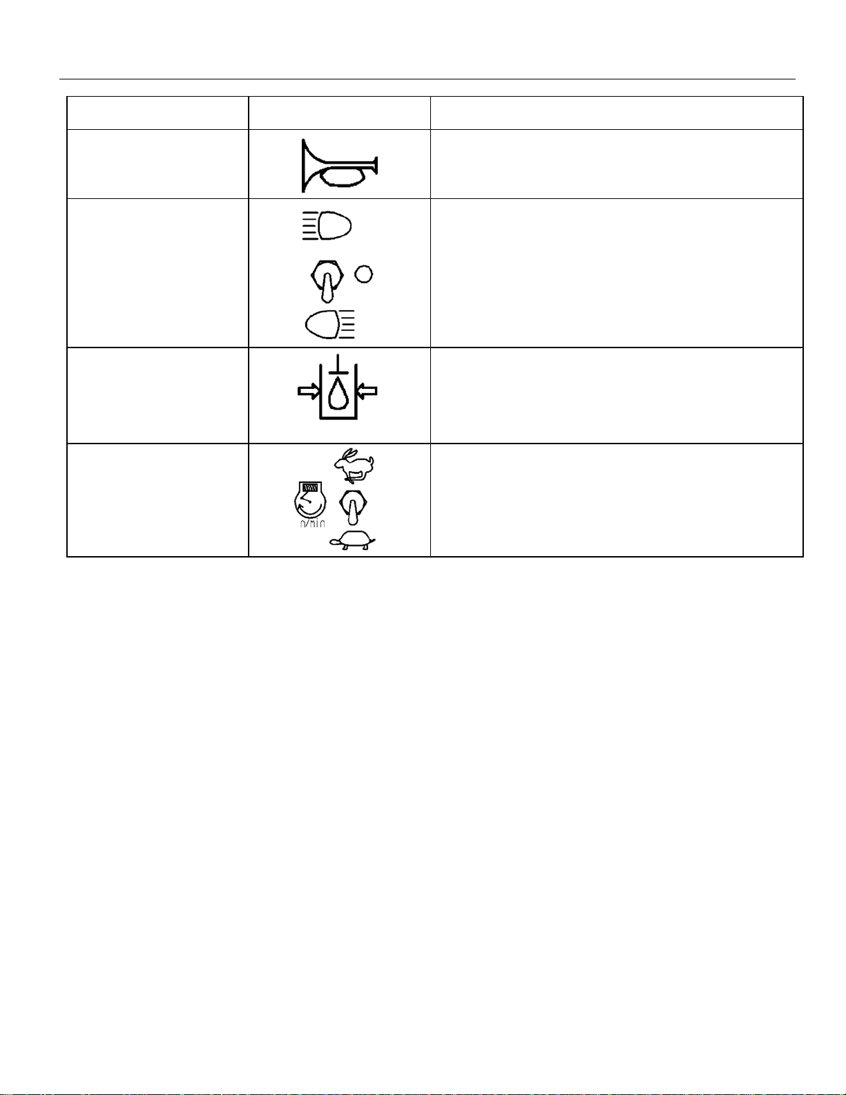
CONTROL OR
INSTRUMENT INTERNATIONAL
SYMBOL
FUNCTION
HORN Pushbutton
Depress switch to sound horn.
TRAVEL LIGHTS Switch
Two position switch to turn running lights on or off.
Pump Switch
ON Position
OFF Position
This switch controls a pump destroke valve that relieves
hydraulic system pressure.
Used during work or traveling.
Must be OFF for starting engine.
ENGINE SPEED Switch
HIGH Speed
LOW Speed
Used during work, travel, and shutdown.
Used during normal work and travel operations.
Used for idling engine for extended periods of time, or for
idling engine for machine shutdown.
Auto-Lift Model “LS-C” OPERATION
JULY/2004 (4945-7900) Section 2-5
MAIN CONTROL PANEL
MACHINE FUNCTION CONTROLS AND GAUGES
CONTROL OR
INSTRUMENT INTERNATIONAL
SYMBOL
FUNCTION
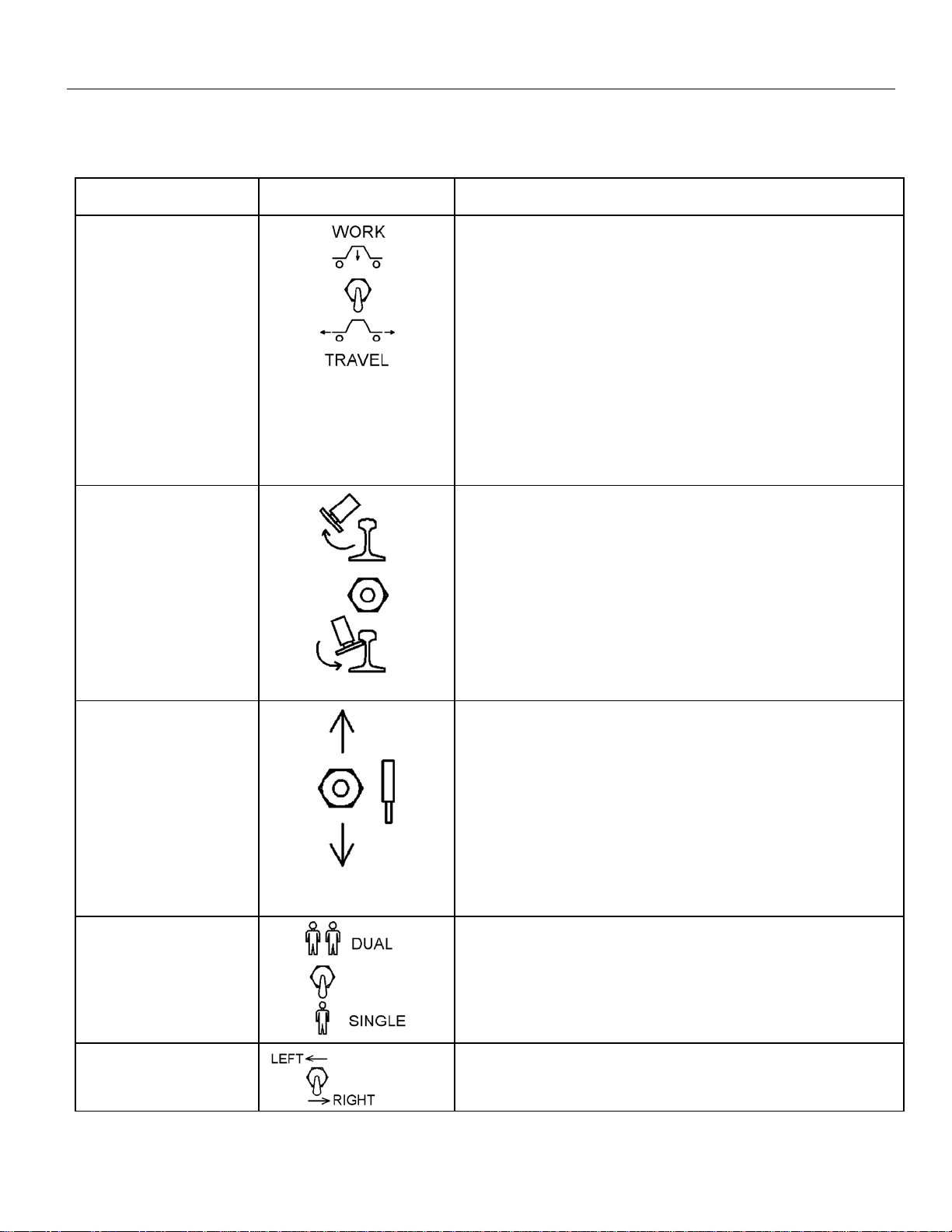
WORK/TRAVEL Mode
Selector Switch
WORK Position
(AUTO MODE)
TRAVEL Position
(MANUAL MODE)
Machine mode selector switch. Two position switch.
Work position energizes the Remote Control Boxes on the
Machine and on the Plate Pusher. Used when operating
machine using the Remote Operator Control Box or the Control
Box on the Plate Pusher to perform work operations.
Travel position disables the use of the remote control boxes on
the machine and plate pushers. This is only used for traveling
or performing adjustments to the lift and/or clamp actions when
changing rail or tie size. In the TRAVEL position, the clamp
and lift functions can only be activated by using the Clamps
Up/Down Switch and Lift Cylinder Up/Down Switch on the
Main Control Panel (not the Remote Control Boxes). See
below for more details on these switches.
CLAMPS UP/DOWN
Switch
CLAMPS UP
CENTER POSITION
CLAMPS DOWN
Used when machine is in the TRAVEL (Manual) position to
extend or retract the rail clamps. Three position spring switch.
Holding the switch UP will retract the clamp cylinders causing
the rail clamps to close.
Releasing switch will automatically stop cylinder/clamp action.
NOTE: Machine should not be travelled if the clamps are
partially up or down.
Holding the switch DOWN will extend the clamp cylinders
causing the rail clamps to open.
LIFT CYLINDER
UP/DOWN Switch
CYLINDER UP
CENTER POSITION
CYLINDER DOWN
Used when machine is in the TRAVEL (Manual) position to
extend or retract the lift cylinders. Three position spring switch.
Holding the switch UP will retract the lift cylinders causing the
rail clamps to lift the rail.
Releasing switch will automatically stop cylinder/clamp action.
NOTE: Machine should not be travelled if the clamps are
partially up or down.
Holding the switch DOWN will extend the lift cylinders causing
the rail clamps to lower the rail.
DUAL/SINGLE Switch
DUAL Mode
SINGLE Mode
Used for selecting one rail or two rail operation.
Used when performing work operations on two rails.
Used when performing work operations on one rail. Operator
must select which side of machine is active. See below.
LEFT/RIGHT Switch
Determines the side of the machine that is active. Left or right
position is determined when operator is standing at the LOGIC
box.
OPERATION Auto-Lift Model “LS-C”
Section 2-6 SEPT/2004 (4945-7900)
MAIN CONTROL PANEL (CONTINUED)
MACHINE FUNCTION CONTROLS AND GAUGES
CONTROL OR
INSTRUMENT INTERNATIONAL
SYMBOL
FUNCTION
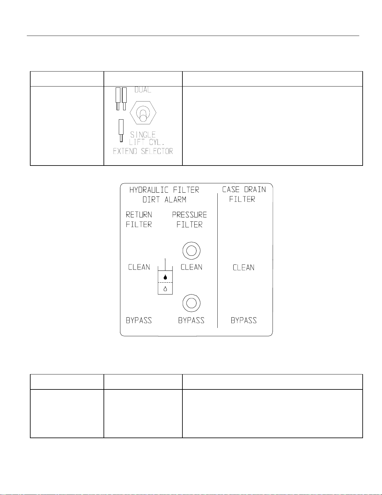
Dual/Single Lift
Cylinder Extend
Two position switch.
Enables the manual over-extend of the lift cylinders.
Dual position is when two operators are working the machine.
Single position is when a single operator is working the
machine. (Operator MUST select which side of the machine
he/she is working.)
MAIN CONTROL PANEL
FILTER STATUS INDICATORS
CONTROL OR
INSTRUMENT INTERNATIONAL
SYMBOL
FUNCTION
FILTER STATUS
LIGHTS
GREEN LIGHT
RED LIGHT
Lights will give status of return & pressure line filters.
Filter does not require servicing.
Alarm state. Filter requires servicing or element requires
replacing.
Table of contents
Other Nordco Industrial Equipment manuals


