diversey TrailBlazer User guide

TrailBlazer®
Assembly and Instruction Manual

Table of Contents
Assembly.....................................................................................................................................................................1
Parts Included ...........................................................................................................................................................1
Handle and Base Plate Mounting Bracket Assembly........................................................................3-9
Base Plate, Base Plate Shaft and Cleanup Tool Assembly ..........................................................10-12
How to Finish Floors with TrailBlazer........................................................................................................... 13
Floor Finish BIB Preparation........................................................................................................................ 13
Feed Line and Base Plate Preparation...............................................................................................14-15
Applying Finish with TrailBlazer ..........................................................................................................16-18
TrailBlazer Cleanup......................................................................................................................................... 19
Changing Filters ........................................................................................................................................20-21

1
Assembly
Parts Included
Main Components
A. Body - (1)
B. Upper Handle - (1)
C. Bail - (1)
D. Hardware Assembly Packet - (1)
E. Lower Handle - (1)
F. Base Plate Support Bar - (1)
G. Base Plate - (1)
H. Base Plate Shaft - (1)
I. Base Plate Springs - (2)
Hardware Assembly Package
J. Lower mounting bracket - (1)
K. Upper mounting bracket - (1)
L.
Lower mounting bracket bolt with star
washer M6-1.0x15mm - (1)
M. M6 locking nut - (1)
N. Washers - (4)
O. 16mm nuts - (5)
P. Upper mounting bracket bolt with star
washer M6-1.0x40mm - (1)
Q. Handle hinge screws - (2)
R. Lock washers - (4)
S. Hand tool - (1)
F
L
E
D
C
A
I
H
G
S
O
N
J
R
M
P
Q
K
B

2
Assembly
Parts Included (continued)
Starter Kit
T. Base plate covers - (3)
U. Short feed line - (3)
V. Long connector feed line - (3)
W. Applicator pad - (1)
X. Manifolds - (3)
Cleanup Tool
Y. Fame - (1)
Z. Cleanup pad - (1)
AA. Cleanup tool clip - (1)
BB. Cleanup tool handle - (1)
Y Z AA BB
T
X
W
V
U

3
Assembly
Handle and Base Plate Mounting Bracket Assembly
After completing steps 1 through 24 your TrailBlazer should look like Figure 1.
Place body (A) onto oor with wheels
facing down. (See gure 2)
1
Figure 2
Figure 1
A

4
Assembly
Handle and Base Plate Mounting Bracket Assembly (continued)
Insert lower handle (E) into guide holes
and slide into place. (Figure 3)
Insert base plate support bar (F) into
guide holes and slide into place. (Figure 4)
9Make sure base plate support bar
has the bracket mounting hole
facing up and away from the lower
handle.
2
3
Figure 3
Figure 4
F

5
Assembly
Handle and Base Plate Mounting Bracket Assembly (continued)
Position body (A) onto its side keeping
the lower handle and base plate
support bar in place. (Figure 5)
Repeat step 5 for the nal three threaded bolts of the lower handle (E) and base plate support bar (F).
6
Position body (A) back onto its wheels.
7
4
Figure 5
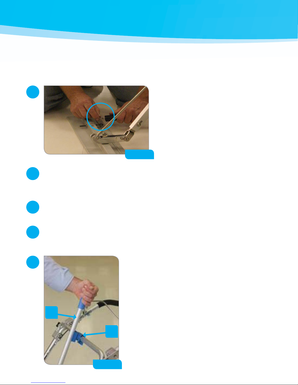
Slide washer (N), locking washer (R)
onto one of the four threaded bolts
of the lower handle (E) and base plate
support bar (F). Then insert nut (O) into
the hand tool (S). Use hand tool (S) to
fully tighten. (Figure 6)
5
Figure 6

6
Assembly
Handle and Base Plate Mounting Bracket Assembly (continued)
Attach upper handle (B) to lower handle
(E) by aligning pivot brackets and hand
tightening with handle hinge screws (Q)
(Figure 7).
9The upper handle is height
adjustable for comfort.
8
Figure 7
Q
Insert cable into cable guide (Figure 8).
9
Figure 8

7
Assembly
Handle and Base Plate Mounting Bracket Assembly (continued)
Attach upper mounting bracket (K) to
base plate support bar (F) with upper
mounting bracket bolt (P) and M6
locking nut (M). Hand tighten with
Phillips head driver on hand tool (S).
(Figure 9)
9Make sure the hanging push
pin is on the closed side of the
TrailBlazer body.
10
Figure 9
F
M
K
P
Attach lower mounting bracket (J)
to body (A) with lower mounting
bracket bolt (L). Hand tighten
with Philips head driver on hand
tool (S). (Figure 10)
9Make sure the hanging
push pin is on the closed
side of the TrailBlazer body.
11
Figure 10
J
L

8
Assembly
Handle and Base Plate Mounting Bracket Assembly (continued)
Locate the four black release knobs on the top face of
the pump cartridge. Rotate each knob 90 to release
pump.
12
Flip pump cartridge over. Insert the squeeze tubing
by inserting one of the barbed ttings back into the
slot in the pump housing, making sure that the clip
end of the tie-wrap on the tubing is facing towards the
centerline of the pump housing.
13
Carefully feed the tubing around the roller assembly in
the pump. Manually turning the roller assembly in the
direction the tubing is being inserted will make inserting
the tube easier.
Insert the other barbed tting into the slot on the other side of the pump.
Hold both barbed ttings down in the pump housing while turning the roller assembly
1 full rotation to seat the tube.
14
15
16

9
Assembly
Handle and Base Plate Mounting Bracket Assembly (continued)
Replace the pump cartridge assembly on the
mounting plate by aligning the toothed drive gear
with the roller assembly and sliding down into
position. Turn the release knobs until the arrows on the
knobs are parallel with the long side of the mounting
plate. Press the release knobs down into the mounting
plate until they “click”.
17
Test that the pump is functioning properly. Lower the bail (C) located on the upper handle (B).
18
Lower the bail (C) on the upper handle (B)
22
Repeat step 18 & 19 to verify that the pump is moving and the clicking sound is gone.
23
Repeat steps 18-22 until the pump is engaging by verifying that the pump is moving
and the clicking sound is gone.
24
Pull the unit backwards at a normal walking speed to make sure the pump is moving and that there is no
clicking noise. If the pump is moving and there is no clicking noise proceed to the Base Plate and Base
Plate Shaft Assembly section.
9If the pump is not moving or there is a clicking noise follow the steps below.
19
Raise bail (C) on the upper handle (B).
20
Loosen the upper cable adjustment
locking nut with a pliers and back the
locking nut about ¼”. (Figure 11) Then
use the pliers to back out the cable
adjustment screw. (Figure 12)
21
Figure 11 Figure 12

10
Assembly
Base Plate, Base Plate Shaft & Cleanup Tool Assembly
After completing steps 1 through 5 your TrailBlazer should resemble Figure 13.
Place base plate (G) at on surface with bolt facing
upward and eyebolts facing body of TrailBlazer. Place base
plate shaft (H) onto bolt and tighten nut (O) with hand
tool (S) (Figure 14).
1
Figure 13
Figure 14

11
Assembly
Base Plate, Base Plate Shaft & Cleanup Tool Assembly (continued)
Position base plate (G) and base plate shaft
(H) into upper mounting bracket (K) and lower
mounting bracket (J) (Figure 15).
While holding base plate shaft (H) in place align
lower bracket guide hole and shaft slot. Insert push
pin through completely to secure. (Figure 16)
Insert base plate shaft (H) fully into upper
mounting bracket (K) behind the guide holes.
Insert pin through the guide holes to secure.
(Figure 17)
2
3
4
Figure 15
Figure 16
Figure 17
H
J
K
12
Assembly
Base Plate, Base Plate Shaft & Cleanup Tool Assembly (continued)
With the base plate (G) in the “down” position,
attach base plate springs (I) to the adjustable base
plate eye bolts. (Figure 18)
Now insert the cleanup tool clip (AA) onto the lower handle (E) and
secure the cleanup tool to the TrailBlazer. (Figure 19)
Verify that the base plate is aligned properly by measuring from the base plate eye bolt to the front wheel.
9If the two sides are not the same distance to the wheel simply loosen one eyebolt, re-measure
until the two sides are the same distance from the front wheels and re-tighten eyebolt nuts.
Now, remove the retaining clip and unthread the nut on the cleanup tool frame (Y).
Take the cleanup tool frame nut and slide onto the cleanup tool handle (BB). Then, insert the cleanup tool
frame (Y) onto the cleanup tool handle (BB). Align the holes and insert the retaining ring. Next, tighten the
nut onto the cleanup tool frame (Y).
5
9
6
7
8
Figure 18
Figure 19
BB
AA

13
How to Finish Floors with TrailBlazer
Floor Finish BIB Preparation
Locate white tap in box and pull until the tap is outside the box.
2
Rotate tap so that the spigot faces the bottom of the BIB.
3
Insert the white tap in the round opening and fold down access tab.
4
Place BIB with the white tap facing the oor onto
TrailBlazer with the white tap on the open side of
the TrailBlazer. (See Figure 21)
5
Figure 21
White Tap
Locate perforated opening for white tap, punch out round
plug and access tab. (Figure 20)
1
Figure 20

14
How to Finish Floors with TrailBlazer
Feed Line & Base Plate Preparation
Attach the long connector feed line and
lter assembly (V) to the white tap, making
sure both locking clips on the connector
engage with the locking tabs on the white
tap.
(Figure 22)
Move the base plate (G) to the “down” position by lowering
the base plate shaft (H). Slide the manifold (X) onto the
base plate with the gray male connector pointing up
(Figure 24).
Attach the free end of the long connector
feed line and lter assembly (V) to the
pump. (Figure 23)
9The pump inlet is the white male
connector on the pump, located on
the open side of the TrailBlazer
1
3
2
Figure 22
Figure 24
Figure 23
V
X
V

15
How to Finish Floors with TrailBlazer
Feed Line & Base Plate Preparation (continued)
Attach one end of the short feed line (U)
onto the gray male connector on the
manifold (X). Slide the free end of the short
feed line (U) to the pump. (Figure 25)
9The pump outlet is the white male
connector on the pump, located on
the closed side of the TrailBlazer
Place an applicator pad (W) on the
underside of the base plate (G). (Figure 26)
9Make sure that the holes in the
manifold are not covered by the
applicator pad
Move the base plate (G) to the “up” position by raising the base plate shaft (H).
4
6
5
Figure 25
Figure 26
U
W

16
* Only do steps 1-6 if the applicator pad has not already been saturated with nish*
Disconnect long connector feed line (V) from the pump inlet.
9The pump inlet is the white male connector on the pump, located on the open side of the
TrailBlazer
1
Attach the free end of the long connector feed line (V) to the pump.
9The pump inlet is the white male connector on the pump, located on the open side of the
TrailBlazer
4
Hold the free end of the long connector feed line (V) behind the manifold (X) and slowly open the
white tap on the BIB.
2
Allow a pool of nish (1–2 sq. ft.) to form then turn o white tap on BIB.
3
How to Finish Floors with TrailBlazer
Applying Finish with TrailBlazer
Turn the white tap on the BIB to the “on”
position and lower bail (C) on upper
handle (B). (Figure 27)
5
Figure 27

17
About 10 feet (3m) before the end of the pass, raise the bail (C) to keep excess nish from being
applied as the TrailBlazer is turned for the next pass.
8
Lower the bail (C) and continue applying nish.
9
How to Finish Floors with TrailBlazer
Applying Finish with TrailBlazer (continued)
Pull the TrailBlazer back and forth a few
times until the initial pool of nish is
absorbed and nish is owing out of the
manifold (X). (Figure 28)
Once the system is primed and the pad is
wet pull the TrailBlazer in the direction you
wish to nish. (Figure 29)
6
7
Figure 28
Figure 29

18
Repeat steps 7 and 8 until the entire area is coated with nish.
10
About 10 feet (3m) before the last pass is nished close the white tap on the BIB and keep the bail
lowered to empty the feed lines and manifold.
11
Once the nal 10 feet are nished raise the bail (C).
12
How to Finish Floors with TrailBlazer
Applying Finish with TrailBlazer (continued)
Between coats place the base plate cover
(T) over the base plate (G). (Figure 30)
9The base plate cover will keep the
applicator pad and manifold damp
for 45 minutes
13
Figure 30
Other manuals for TrailBlazer
1
Table of contents
Other diversey Floor Machine manuals

diversey
diversey TASKI swingo 760E User manual

diversey
diversey swingo 4000 User manual

diversey
diversey Taski swingo XP CO75XP.2 User manual

diversey
diversey TASKI swingo 1655 XD User manual

diversey
diversey TASKI swingo 1260B Power User manual

diversey
diversey TASKI swingo 1260B Power User manual

diversey
diversey Taski ergodisc 2000 User manual
Popular Floor Machine manuals by other brands


Pacific
Pacific B-1500 Parts & operating manual

American-Lincoln
American-Lincoln 7765 56514750 Instructions for use & warranty

Janser
Janser 135SH User instructions
 Operator's manual")
Clarke
Clarke 56381408 (21KBCATCLDC) Operator's manual

Nilfisk-Advance
Nilfisk-Advance Terra 4300B 9084317010 Instructions for use

Mercury
Mercury HD-22 Safe Operations