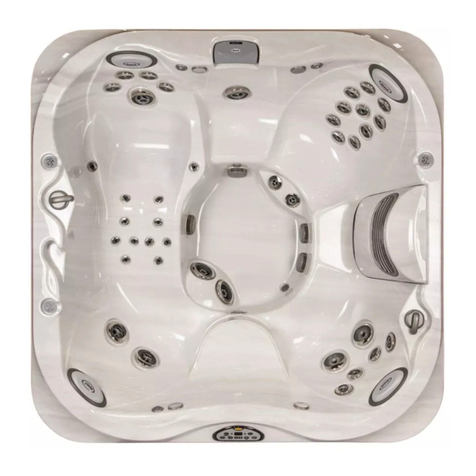
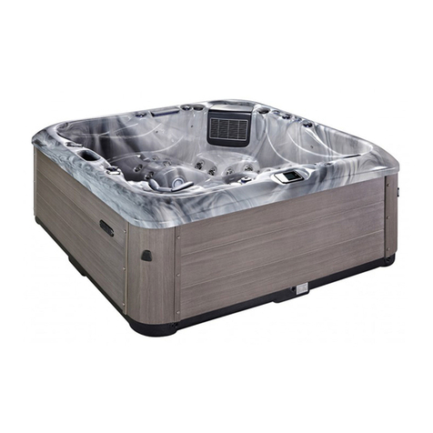
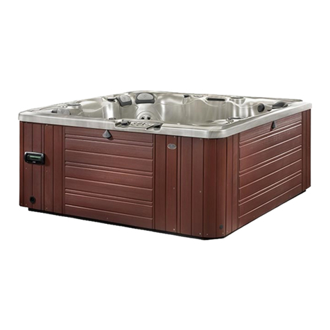
Divine Hot Tubs Deluxe Series User manual

Divine Hot Tubs™ Deluxe | Euro
SPA MANUAL-50HZ
Deluxe Series
P.O. Box 2140 | Woodinville, WA 98072 | U.S.A.
www.divinehottubsdeluxe.com
live better | feel better
DELUXE
© August, 2016 | Divine Hot Tubs™ Deluxe | spa manual divine dlx UK, Euro 8-15-16

“We reserve the right to improve our product without notice”
Copyright © Divine Hot Tubs™ Deluxe, August, 2016 (A division of Thermal Hydra Plastics, LLC.).
All rights reserved. Specications may change without notice. International products may be congured
dierently to meet local electrical requirements.

3
TABLE OF CONTENTS
5 INTRODUCTION
5 ICON Key
6 IMPORTANT SAFETY INSTRUCTIONS
6 Read and Follow All Instructions
8 STEPS FOR POSITIONING YOUR SPA
8 Local Codes
8 Delivery Passageway
8 Location & Base
8 Installation and Electrical Hookup
9 Electrical Requirements
15 Filling Your Spa
16 TOPSIDE CONTROL - TURNING ON YOUR SPA
16 Topside Control Button Reference Display, 1/2/3 Pumps
19 WATER PURITY & FILTRATION
19 Keeping The Water Clean
19 Spa Chemistry 101
21 How To Use the Chemicals
21 Usage Denitions
22 Starting A Chemical Maintenance Program
24 Filtration
25 Ozone Generator
26 JETS
26 Types Of Jets
27 Jet, Air and Waterfall Controls
27 Cleaning The Rotating Jets
28 Jet Removal

4
28 MAINTENANCE & MISCELLANEOUS
28 Pillows
28 Spa Cabinet Skirt
28 The Shell
29 Spa Cover
29 Winterizing
30 Draining The Spa
32 APPENDIX A
32 Troubleshooting
32 System Trouble
32 Controls
33 Pumps
33 Jets
33 Water
35 FAQ’s - Frequently Asked Questions
36 Wi-Fi Module – Supplement
37 Bluetooth Pairing Guide – Supplement
38 Notes
40 Warranty

5
INTRODUCTION
Congratulations on your purchase of your new hot tub! Your
hot tub is designed and manufactured with the nest compo-
nents available and is engineered with comfort, low mainte-
nance, and durability in mind.
You will enjoy your spa for several years to come if you are dili-
gent with the care and maintenance of your spa. This manual
will help you to determine the best way to take care of your spa
based on the amount of use and the type of environment your
spa is installed.
It is very important for you to read the entire manual before
attempting to use your spa. Contained in this manual are im-
portant
maintenance and start-up procedures as well as safety
precautions that must be followed to ensure the prolonged life
of your spa and the safety of the people using the spa. Failure
to follow start-up procedures may damage your unit and void
your warranty.
Please feel free to contact us if you have any further questions
after reading this manual. We hope you enjoy many years of
fun and relaxation in your new hot tub
ICON Key
The Icon key on the left denes the type of information boxes
that will appear throughout the manual. The boxes highlight
helpful information that contains useful tips or warnings that
apply to the use and care of your spa.
Warning!
Safety Tip
Key Point
ICON KEY

6
SAFETY FIRST
IMPORTANT SAFETY INSTRUC-
TIONS! READ AND FOLLOW ALL
INSTRUCTIONS. SAVE THESE
INSTRUCTIONS.
Electrical
Warning!
When installing and using this
electrical equipment it is rec-
ommended that a licensed and
bonded electrician perform
the work. Basic safety precautions
should always be followed, including the
following:
• Apressurewireconnectorisprovidedon
the outside of the control box to permit
the connection of a solid copper bond-
ing wire between the spa and any metal
equipment, metal enclosures of electri-
cal equipment, metal water
pipe or conduit within 5
feet of the spa as needed to
comply with local require-
ments.
• A green colored termi-
nal (or a wire connector
marked “G”, “GR”, “Ground”,
or “Grounding”) is provided.
To reduce the risk of electric shock, con-
nect this terminal to the grounding ter-
minal of your electric service or supply
panel with a continuous green insulated
copper wire equivalent to the circuit con-
ductor supplying this equipment.
• The electrical supply must include a
suitably rated Ground Fault Interrupter
Circuit to open all underground supply
conductors to comply with section 422-
20 of the National Electrical Code. ANSI/
NFPA 70-1987. The power supply cut o
must be readily accessible to the spa oc-
cupant, but installed at least 5 feet from
spa water.
• TesttheperformanceoftheGFCIaccord-
ing to manufacturers recommendations.
If the GFCI does not perform correctly,
there may be a ground current ow-
ing indicating the possibility of electric
shock. Disconnect the power until the
fault has been identied and corrected.
Electrical
Warning!
• DANGER –RISK OF ELEC-
TRIC SHOCK. Install at least 5
feet from all metal surfaces.
• DANGER – RISK OF ELEC-
TRIC SHOCK. Do not permit any electric
appliance such as a light, telephone, ra-
dio or television within 5 feet of a spa or
hot tub.
• WARNING –RISK OF CHILD DROWN-
ING. Extreme caution must be exercised
to prevent unauthorized access by chil-
dren. To avoid accidents, ensure that
children cannot use a spa or hot tub un-
less they are supervised at all times.
Safety
Warning!
• DANGER – To reduce risk of
injury, do not remove suction
ttings.
• Installation should provide
drainage of the electrical equipment
area to prevent electrical shortage.
• Storeallchemicalsinacooldryareaand
keep out of children’s reach.
• Toreducetheriskofinjury:
A. Spa heat can cause hyperthermia and
unconsciousness! The water in a spa or
hot tub should never exceed 104° F (40°
C). Water temperatures between 100° F
(38° C) and 104° F (40° C) are considered
safe for a healthy adult. Lower water
temperatures are recommended for ex-
WARNING
PREVENT DROWNING
1. SUPERVISE CHILDREN AT ALL TIMES.
2. ATTACH SPA COVER AFTER EACH USE.
3. SPA HEAT CAN CAUSE HYPERTHERMIA AND
UNCONSCIOUSNESS.
4. SPA HEAT IN CONJUNCTION WITH ALCOHOL,
DRUGS, OR MEDICATION CAN CAUSE
UNCONSCIOUSNESS.
PREVENT ELECTROCUTION
1. NEVER PLACE ANY ELECTRIC APPLIANCE
WITHIN 5 FEET OF SPA.
NOTE: THIS MARKING IS TO BE REMOVED ONLY BY THE CUSTOMER.
!
r

7
tended use (exceeding 10 –15 minutes)
and for young children.
B. Since excessive water temperatures have
a high potential for causing fetal damage
during the early months of pregnancy,
pregnant or possibly pregnant women
should limit water temperatures to 100°
F (38° C).
• Theuseofalcohol,drugs,ormedication
before or during spa or hot tub use may
lead to unconsciousness with the possi-
bility of drowning.
• Personssueringfromobesityorwitha
medical history of heart disease, low or
high blood pressure, circulatory system
problems or diabetes should consult a
physician before using a spa or hot tub.
• Persons using medication should con-
sult a physician before using a spa or hot
tub since some medication may induce
drowsiness while other medication may
aect heart rate, blood pressure, and cir-
culation.
• Before entering a spa, the user should
measure the water temperature since
the tolerance of water temperature-reg-
ulating devices varies.
Electrical
Warning!
WARNING – he spa (appliance)
is not to be used by persons
(including children) with re-
duced physical, sensory or
mental capabilities, or lack of
experience and knowledge,
unless they have been given supervision
or instruction.
• Childrenshouldbesupervisedtoensure
that they do not play with the spa (appli-
ance).
• Parts containing live parts, except parts
supplied with safety extra-low voltage
not exceeding 12 V, must be inaccessible
to a person in the spa (bath).
• Earthedappliancesmustbepermanent-
ly connected to xed wiring.
• Parts incorporating electrical compo-
nents, except remote control devices,
must be located or xed so that they can-
not fall into the spa (bath).
• The spa (appliance) should be supplied
through a residual current device (RCD)
having a rated residual operating current
not exceeding 30 mA.
• If a stationary spa (appliance) is not t-
ted with a supply cord and plug, or with
other means for disconnection from the
supply mains having a contact separa-
tion in all poles that provide full discon-
nection under overvoltage category III
conditions, the instructions shall state
that means for disconnection must be
incorporated in the xed wiring in accor-
dance with the wiring rules.
Safety
Warning!
CAUTION – In order to avoid a
hazard due to inadvertent re-
setting of the thermal cut-out,
this spa (appliance) must not
be supplied through an exter-
nal switching device, such as a timer, or
connected to a circuit that is regularly
switched on and o by the utility.

8
Positioning of your spa
When selecting a site for your spa, take into
account the following:
Local Codes:
There may be certain restrictions and/or
requirements that are particular to your
locality. If in doubt, check with your local
council.
Delivery Passageway:
The spa will arrive as a unit, and cannot be
disassembled. Ideally the spa will be placed
on a trolley, either on its side or on its base.
The unit will then be rolled into place eas-
ily crossing grass, gravel, and small terrain
anomalies. For safe and non-intrusive in-
stallation, we require an opening not less
than the size of your spa plus at least 40cm
height for the trolley and a minimum of
5cm clearance on each side. If your access
does not meet these conditions, or in the case of other obstacles (steps, fences,
walls, steep hills, etc.) contact Divine Hot Tubs Deluxe for advice and conditions.
Location & Base:
A sheltered environment can result in lower operating and maintenance costs. You
must allow 1 meter clearance for access to the spa’s access panel for servicing.
• The site you select for your spa MUST be a at, level continuous surface that
fully contacts the bottom of the spa.
• Your new spa weighs between 300-450kg when dry, and when lled to capac-
ity weighs 900-2300kg. Therefore a solid support is essential when the spa
is mounted on a deck or ground level patio/oor. We recommend that you
install your spa at ground level. This allows easy access to equipment.
• A 10 to 15cm thick re-enforced concrete slab is ideal, but not required. In most
cases your spa can be placed on properly installed existing patios.
• The base must be at least the size of the bottom of your spa.
• Water should always drain away from the spa. DO NOT locate your spa in a low
run-o area since melting snow or rain could ood the area and cause pump
and equipment damage.
• DO NOT situate spa near or under overhead wires, keeping clear of all electri-
cal appliances.
Installation and Electrical Hookup:
Have a licensed electrician run the required 230-volt power line to the spa instal-
lation site. This power line must be permanently connected (hard-wired) to the
mains supply. Do not use extension cords or plug-in type connections. At the site
where the spa is to be located leave 5 meters of cable and the appropriate cable
gland. All electrical wiring to a spa must be installed by a qualied, licensed elec-
trician, and meet local building/electrical codes. A certicate from the electrician
verifying it has been tested must be obtained.

9
PLEASE NOTE: Failure to supply the recommended power will void the Manufac-
turer’s Warranty!
Electrical requirements
System Box Wire Gauge Check
When inspecting the wiring for any control system, note that connections for the
incoming wires are clearly labeled at the main terminal block.
• Two 16A service - minimum twelve guage
copper wire per line (each).
• 30A service – minimum ten gauge copper wire.
• 40A service – minimum eight gauge copper wire.
• 50A service – minimum six gauge copper wire.
These wires must connect the house breaker box, through the local disconnect, to
the main terminal block. The wiring diagram inside the system box shows the main
terminal block as TB1.
Important
Using non-copper wire can be dangerous, and also can be the cause of a spa’s mal-
function. If non-copper wire is used at any point, we do not recommend servicing
the spa until an electrician replaces it with the proper gauge copper wire.
Important
This service must be single phase. Any abnormal voltage reading requires an elec-
trician. Do not attempt to x these types of problems yourself. High voltage can
seriously injure or kill.
R.C.D. Wiring Check
If a Residual Current Device has recently been installed, a majority of tripping prob-
lems can be attributed to incorrect wiring of the R.C.D. A clear understanding of the
correct conguration is essential. Please refer to the gure on page 15 as needed.

10
Wiring Check for R.C.D./Service Disconnect
Precautions
In most areas, R.C.D.’s are required for spa installations. In other areas, R.C.D.’s are
recommended for spa installations, but are not mandatory.
If the spa you are servicing was not installed with a R.C.D.,
strongly urge your customer to improve safety and comply
with current standards by installing one.
Note: A suitable R.C.D. may be acquired through your local dis-
tributor.
Important: Remember, high voltage is still
accessible in the house breaker box even
though you have turned o the spa breaker.
R.C.D. Line-in Wiring Check
• Locatethepropercircuitbreakerandturnito.
• Removethecoverfromthehousebreakerbox.Checkthemainservice
amperage rating to the breaker box. Note: Typically, a house circuit will
require at least a 100 Amp service when a spa is installed.
• Fromthecircuitbreaker,locatethebrownloadwireandtheblueneutralwire.
• FromtheR.C.D.neutralbar,locatetheblueloadneutral,andthegreen
ground wire.
• Besuretherearenootherappliancesonthespacircuit.Ifthereare,service
must be re-wired to supply the spa only.
• Makesureallthreewiresexitthehousebreakerboxviaconduit,routedto
the R.C.D. breaker box. The brown should be connected to the R.C.D. line-in.
The blue load neutral connects to the neutral in.
R.C.D. Line-out Wiring Check for 230 V Dedicated System
(3 wire system including ground wire)
The brown wire should connect to load out, the blue wire from neutral out. All wires
will exit the box via conduit routed to the spa control system.
Once you have found all wiring correctly installed, begin to check for proper
voltage.
Voltage Checks - System Box R.C.D. |
Load Out Voltage Check
230 V Dedicated System:
• Besurethehousebreakerison.
• BesuretheR.C.D.breakerison.
• ProbetheblueandbrownwiresattheR.C.D.loadout.Thevoltageshouldbe230V.
• Probethebluewireandthegreengroundwire.Themetershouldread0V.
• ProbethebrownwireandtheR.C.D.neutralbar.Thevoltageshouldread230V.
• Recheckvoltageunderpeakloadconditions.*

11
Important!
If the voltage is not within the acceptable range, call an electrician or the local
electric company to diagnose the problem.
System Box Check (at TB1)
230 V Dedicated System Check:
• BesuretheR.C.D.breakerison.
• Probetheblueandbrownwires.Lookfor230V.
• Probetheblueandgreengroundwiresfor0V.
• Probethebrownandgreengroundwires–also230V.
• Recheckvoltageunderpeakloadconditions.*
* Peak Load Check
It is important to check the voltage again under peak load conditions. To reach
peak load, turn on the blower, heater, light, and all pumps.
Peak Load Check for 230 V System:
• Checkthevoltagebetweentheblueandbrownwires.Theacceptablevoltage
range is between 207 and 253 V.

12
ELECTRICAL WIRING SCHEMATIC
IMPORTANT: Electrical connections must be made by qualied, licensed
personnel. Please contact a licensed residential electrician for these services.
Blue
(Neutral)
Blue
(Neutral)
RCD Breaker Box
230VAC House
Breaker Box
Spa System Box
NOTE:
See next page,
“Electrical Service
Congurations
Options”for your
particular spa.
Outside Ground Rod
Green/
Yellow
(Ground)
Blue (Neutral)
Brown (Hot)
Blue
(Neutral)
Green/
Yellow
(Ground)
Green/
Yellow
(Ground)
Brown
(Hot)
Spa System Box Detail
Blue(Neutral)Brown (Hot)
Grounding Lug
Brown
(Hot)
230 VAC
“Live Wire”
Neutral +
Ground
Brown
(Hot)
Green/
Yellow
(Ground)

13
SINGLE SERVICE FEED
230VAC, 50Hz*, 1þ, 32A,
(Circuit Breaker rating =
40A max.)
DUAL SERVICE FEED
Setup 5 / Programmation 5 /
Konguration 5
400VAC, 50/60Hz*, 3þ, 16A,
(Circuit Breaker rating =
2x16A max. each phase
line)
DUAL SERVICE FEED
Setup 8 / Programmation 8 /
Konguration 8
Pump 1 and Pump 2 are on line 2; Heater and
Pump 3 and Pump 4 are on line 1.
Pump 1 is on line 2; Heater and Blower are on line 1.
TB1
1
2
3
4
4
J45
J110
J79
J54
J77
J75
J78
GREEN
BLUE
BROWN
230V 1þ / 1x32A
ELECTRICAL SERVICE CONFIGURATION OPTION
For DIP Switch Congured System

14
Pump 1 is on line 2; Heater and Pump 2
are on line 1.
230V 3þ / 3x16A
GREEN
BLUE
1 BROWN
2 BROWN
3 BROWN
TB1
1
2
3
4
4
J78
J45
J79
J54
J77
J75
DUAL SERVICE FEED
Setup 9 / Programmation 9 /
Konguration 9
TRIPLE SERVICE FEED
IMPORTANT - Service must
include a neutral wire, with a line
to neutral voltage of 230VAC.
*BPsystemsautomaticallydetect
50Hz vs 60Hz.
...continued
ELECTRICAL SERVICE CONFIGURATION OPTION
For DIP Switch Congured System
ADDITIONAL PRODUCT RESOURCES
AND DOWNLOADS
For additional product resources, manuals and other helpful information, please visit our
website at www.divinehottubsdeluxe.com

15
5. FILLING YOUR SPA THROUGH
THE FILTER CHAMBER
Before you begin to ll your spa, it is advisable to have your water
tested for hardness (water rich in calcium and mineral content). Wells
usually contain harder water than urban water supplies. Mineral and
metal imbalances in your water can shorten the life of the equipment
in your spa. Contact your local hot tub dealer for proper water analy-
sis.
We recommend that you purchase a high quality “Water Test Kit” for
checking pH and sanitizer levels. Test the water daily until your “user
load” is determined.
Make sure there is no dirt or sediment at the bottom of the tub and
that there is nothing inside the lter compartment before lling with
water. Filling the spa through the lter housing will help to prevent
air locks (trapped pockets of air) in pumps on start up.
Identify your lter housing and ll as shown:
pTOPACCESS SINGLEFILTER HOUSING WITH TELESCOPING WEIR AND
SINGLE FILTER HOUSING WITH TURBINE VANE FILTER COVER not shown)
pFRONTACCESS DUALFILTER HOUSING
OR FRONTACCESS SINGLEFILTER HOUSING NOT SHOWN
1. Place your garden
hose into the lter
housing. This will ensure
that air bubbles are
removed from the lines
while you ll the spa.
2. Turn the water on so
that most of the water
enters through the lter
chamber.
3. Fill the water to the
proper level – half way
up the lter housing, just
below the head pillow
or just under the neck
jets as shown in pictures
above.
IMPORTANT!
Improperly
balanced
water may
damage your
spa and void
your warranty!
IMPORTANT!
Do not ll your
tub with water
from your hot
water heater!

16
TOPSIDE CONTROLS: TP600
TURNING ON YOUR SPA
PUMP 1
PUMP 2LIGHT
PUMP 3HEATLIGHTPUMP 1PUMP 2
WARM
COOL
38.5
Figure 1: TP600 control panel, 6-button (3 pumps)
PUMP 1
PUMP 2LIGHT
FLIP HEATLIGHTPUMP 1PUMP 2
WARM
COOL
38.5
Figure 1: TP600 control panel, 6-button (2 pumps)
PUMP 1
LIGHT
FLIP HEATLIGHTPUMP 1
WARM
COOL
38.5
Figure 2: TP600 control panel, 5-button (1 pump)
Start Up
When the GFCI for the spa is switched on to supply power, a startup sequence of
numbers will appear on the display. If no button is pressed, LINK will appear after
the startup sequence. Press any button to link the panel with the system.
The spa will enter Priming Mode. After Linking, press the Jets Button(s) to
turn the pumps on and o to verify that all air is purged from the plumbing, partic-
ularly the plumbing associated with the heater. If the spa uses a circulation pump,
the Light Button turns the Circ Pump on an o during Priming Mode. Priming
Mode will end automatically in 4 minutes. Pressing a Temperature Button will exit
Priming Mode manually. When Priming Mode ends, Pump 1 low will start, if no circ
pump is present, however the water temperature will not appear for a minute or so.
Once the water temperature is recognized by the system, and if it is below the Set
Temperature, the heater will start.

17
Basic Operation
The Up and Down buttons are often referred to as Temperature Buttons.
Some panels only have a single Temperature Button. Press a Temperature Button
once and the current Set Temperature will begin to ash on the LCD. (The Set Tem-
perature and the actual water temperature are often dierent.) While the numbers
are ashing, press a Temperature Button again to change the Set Temperature.
Press-and-hold for faster adjustment. After the new Set Temperature stops ash-
ing, in about 10 seconds, the actual temperature is displayed again and the new
Set Temperature is programmed. The spa will now heat to the new Set Temperature
as needed.
The Light Button turns the Spa Light on and o and is also used in conjunctions
with the Temperature Button(s) to navigate the system menus.
Programming
Refer to the TP600 User Guide for detailed operation,
programming and message instructions. 38.5O[
READY RANGE
p
FLTR 1
Navigating the deeper menu structure is done with only 2 or 3 buttons on the
control panel. Pressing the Light button while the Set Temperature is ashing will
enter the menus. Pressing Light after that will proceed through the menu choices.
Pressing a Temperature Button while any menu item is showing will either edit it
directly or begin an editing sequence.
Depending on the screen displayed, waiting between 10 and 30 seconds will allow
the panel to return to normal operation and a display of spa status.
Filtration
The system is factory-programmed with one lter cycle that will run in the evening
(assuming the time-of-day is properly set) when energy rates are often lower. The
lter time and duration are programmable. Refer to the TP600 User Guide for detailed
instructions.
A second lter cycle can be enabled as needed.
Dual Temperature Ranges
This system incorporates two temperature range settings with independent set
temperatures. The High Range is indicated in the display and might be set be-
tween 26.6°C and 40°C. The Low Range is indicated in the display and might
be set between 10°C and 37.2°C. Low Range may be economical during non-use
periods.
More specic temperature ranges, such as 10°C to 26.1°C for low range, or 32.2°C to
40°C for High Range, may determined by the manufacturer.
Ready and Rest Modes
If the ltration pump is a 2-Speed Pump 1, READY Mode will circulate water every
1/2 hour, using Pump 1 Low, in order to maintain a constant water temperature,
heat as needed, and refresh the temperature display. This is known as “polling.”

18
REST Mode will only allow heating during programmed lter cycles. Since polling
does not occur, the temperature display may not show a current temperature until
the ltration pump has been running for a minute or two. READY/REST Mode may
appear when Jets 1 is activated.
Complete User Guide Reference
Download the complete User Interface and Programming Guide at
http://service.balboa-instruments.com/zz40940_download.zip
The Ground Fault Circuit Interrupter (GFCI) or Residual Current Detector (RCD) is an
important safety device and is required equipment on a hot tub installation.
(The GFCI Test Feature is not available on CE rated systems.)
Used for verifying a proper installation
Your spa may be equipped with a GFCI Protection feature. If your spa has this feature
enabled by the manufacturer, the GFCI Trip Test must occur to allow proper spa
function.
Within 1 to 7 days after startup, the spa will trip the GFCI to test it. (The number
of days is factory programmed.) The GFCI must be reset once it has tripped. After
passing the GFCI Trip Test, any subsequent GFCI trips will indicate a ground fault
or other unsafe condition and the power to the spa must be shut o until a service
person can correct the problem.
Forcing the GFCI Trip Test (North America Only)
The installer can cause the GFCI Trip Test to occur sooner by initiating it using the
above menu. The GFCI should trip within several seconds and the spa should shut
down. If it does not, shut down the power and manually verify that a GFCI breaker
is installed and that the circuit and spa are wired correctly. Verify the function of
the GFCI with its own test button. Restore power to the spa and repeat the GFCI
Trip Test.
Once the GFCI is tripped by the test, reset the GFCI and the spa will operate normally
from that point. You can verify a successful test by navigating to the above menu.
PASS should appear after a temp button is pressed from the GFCI screen.
Warning:
The end-user must be trained to expect this one-time test to occur and how to
properly reset the GFCI. If freezing conditions exist, the GFCI or RCD should be
reset immediately or spa damage could result.
CE Product:
CE registered systems do not have an RCD Test Feature due to the nature of the
electrical service. Some UL registered systems do not have the GFCI Test Feature
activated. The end-user must be trained how to properly test and reset the RCD.

19
WATER PURITY & FILTRATION
Keeping the water clean – chemical sanitizers
One of the bigger reasons that people require service on their spa is because they
haven’t followed a chemical application regiment. Water can accumulate
impuri-
ties that can worsen the performance or even damage the ltration system
if chemicals
are not applied on a regular basis. The water can even become
unhealthy if chemicals
are not used to sanitize the water. Improper pH levels or calcium levels can cause
either corrosion of parts or scale build-up.
IMPORTANT!
Always read
directions on
chemical
container
thoroughly
before
using spa
chemicals.
We recommend that you begin a routine of applying chemicals that
you can get comfortable with and follow all the time. If you get into
a scheduled regiment, it will be easier to remember when to apply
the chemicals.
Your spa comes with an ozonator that will do a very good job at kill-
ing bacteria and oxygenating the water, but chlorine or bromine are
used to compliment the job of the ozonator.
Finally, the best way to keep the water clean over long periods of
time is to change the water four times a year. Connect a hose to the
drain valve and open it all the way to allow the tub to drain all the way. Use a shop-
vac to remove any standing water and debris at the bottom of the tub. Refer to the
maintenance section for instructions on cleaning the tub before relling it.
The pH scale
goes from
0 to 14, with
zero being
extremely
acidic and 14
being extremely
base (alkaline).
Seven is
considered
neutral pH.
Spa Chemistry 101
At rst, trying to understand spa chemistry can seem like a daunt-
ing task to say the least. We intend on helping you understand spa
chemicals so that you can maintain the health of your spa at the best
level possible.
There are three basic principals to spa water chemistry.
1. Sanitize/Disinfect (kill viruses, germs, etc.)
2. Oxidize (break down organic compounds like oils and sweat)
3. Maintain slightly base (alkaline) water (pH of 7.4 - 7.6). This
controls the corrosiveness of the water, prevents excessive
scaling (mineral formation on surfaces exposed to water, and
insures that the water is comfortable to the skin.
Once you have a good understanding of the chemicals that are used
in your spa, you will be able to maintain proper water balance. Water balance is
reached when all elements (pH, total alkalinity, calcium hardness and total dis-
solved solids) are within their proper ranges.
The following denitions for chemicals will help you understand what the chemical
is and what it is used for:

20
Sanitizers
CHLORINE - Chlorine is widely used as a sanitizer or disinfectant in pool and spa
water to kill bacteria, viruses and algae, and oxidizes ammonia
and nitrogen com-
pounds such as swimmer waste. Its formal name is Sodium
Dichlor and is referred
to as a chlorinated concentrate. Sodium Dichlor is a fast-dissolving, granular, stabi-
lized organic chlorine compound
providing either 56% or 63% available chlorine.
Cyanuric acid
and/or stabilizers are added to prevent U.V. light destruction of the chlo-
rine
by the sun.
Chlorinated concentrate produces chlorides and chloramines, which are formed
when chlorine has combined with ammonia and nitrogen in pool and spa water.
Chloramines exude a foul,“chlorine”odor and causes skin and eye irritation.
BROMINE – Bromine is the other commonly used sanitizer or disinfectant in pool
and spa water to kill bacteria and algae, and oxidizes ammonia and nitrogen com-
pounds such as swimmer waste. This chemical does not eliminate swimmer waste
unless it is combined with an oxidizer (non-chlorine shock). It is very susceptible
to direct sunlight, therefore is not ecient in outdoor pools. Bromine is sometimes
used as an alternative for people whom are allergic or sensitive to chlorine products.
Bromine products are available as sodium bromide and bromine tablets. The bro-
mide ion has no eective disinfectant or sanitizing capabilities without the use of
nonchlorine shock (potassium monopersulfate). Potassium monopersulfate is added
to oxidize, or activate, bromide ion to bromine, which rapidly forms the active sanitiz-
er - hypobromous acid - in spa water. Upon reaction with bacteria and other spa con-
taminants, hypobromous acid is reduced back to bromide ion, ready to be activated
again by the next dose of potassium monopersulfate. Potassium monopersulfate
begins to produce bromine immediately and continues to do so for several hours,
providing sucient time for oxidation of bather waste and other organic contamina-
tion such as ammonia and nitrogen.
NON-CHLORINE SHOCK (Potassium Monopersulfate) – Also known
as“Oxy-Shock”, is an important chemical used in the process of disinfecting and sani-
tizing the spa water. Non-chlorine shock is used as an oxidation agent to oxidize
and eliminate organic contaminants, dead algae and debris, and will also convert the
chlorine by-products (chlorides and chloramines) back into free available chlorine.
When used with bromine products, non-chlorine shock is used with sodium bromide
in a two-part disinfection system. Potassium monopersulfate (non- chlorine shock) is
added to oxidize, or activate, bromide ion to bromine which rapidly forms the active
sanitizer - hypobromous acid - in spa water. Upon reaction with bacteria and other
spa contaminants, hypobromous acid is reduced back to bromide ion, ready to be
activated again by the next dose of potassium monopersulfate.
Most non-chlorine shock products have buers that reduce pH instability, and corro-
sion inhibitors that help protect the heater and other metal surfaces.
OZONE – Ozone is a powerful gas that is used as a sanitizer and an oxidant to keep
the spa water clean and disinfected. Although ozone is about 3000 times more
powerful than chlorine, it has a tendency to dissipate quickly and does not create
any sanitizer residual. By using an ozonator for your spa, you can cut maintenance
time and chemical costs by as much as 60%. Ozone is manufactured by an ozonator
(ozone generator) and is dispensed during the ltration mode.
Other manuals for Deluxe Series
2
Table of contents
Other Divine Hot Tubs Hot Tub manuals