DIXIE GRINDERS 1666D User manual
DIXIE GRINDERS INC.
1324 RAILROAD AVE. GUNTERSVILLE, AL 35976
(800) 745-0586 (256) 582-0477 FAX (256) 582-0478
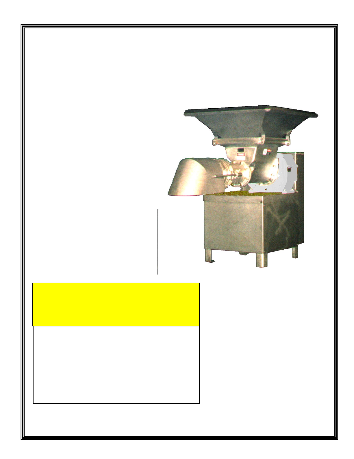
MODEL 1666D
GRINDER UNIT
SAFETY INSTALLATION OPERATION MAINTENANCE
THIS MANUAL MUST BE READ TO,
OR BY EACH PERSON, BEFORE
THAT PERSON OR DEPARTMENT
UNCRATES, OPERATES,
MAINTAINS, OR SUPERVISES USE
OF THIS MACHINE IN ANY WAY.
CAUTION
2
IMMEDIATE HAZARDS
WHICH WILL RESULT IN
SEVERE PERSONAL INJURY
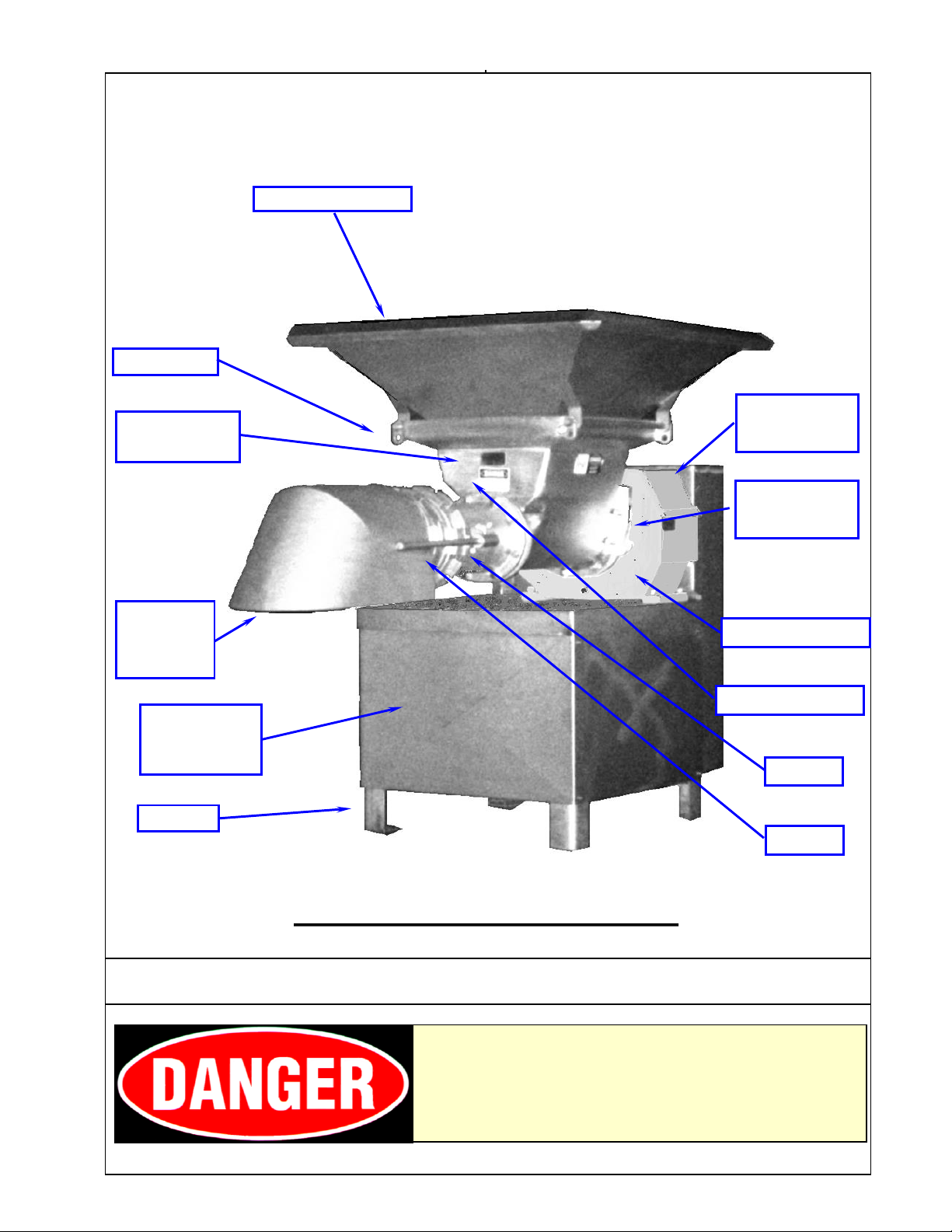
HOPPER GUARD
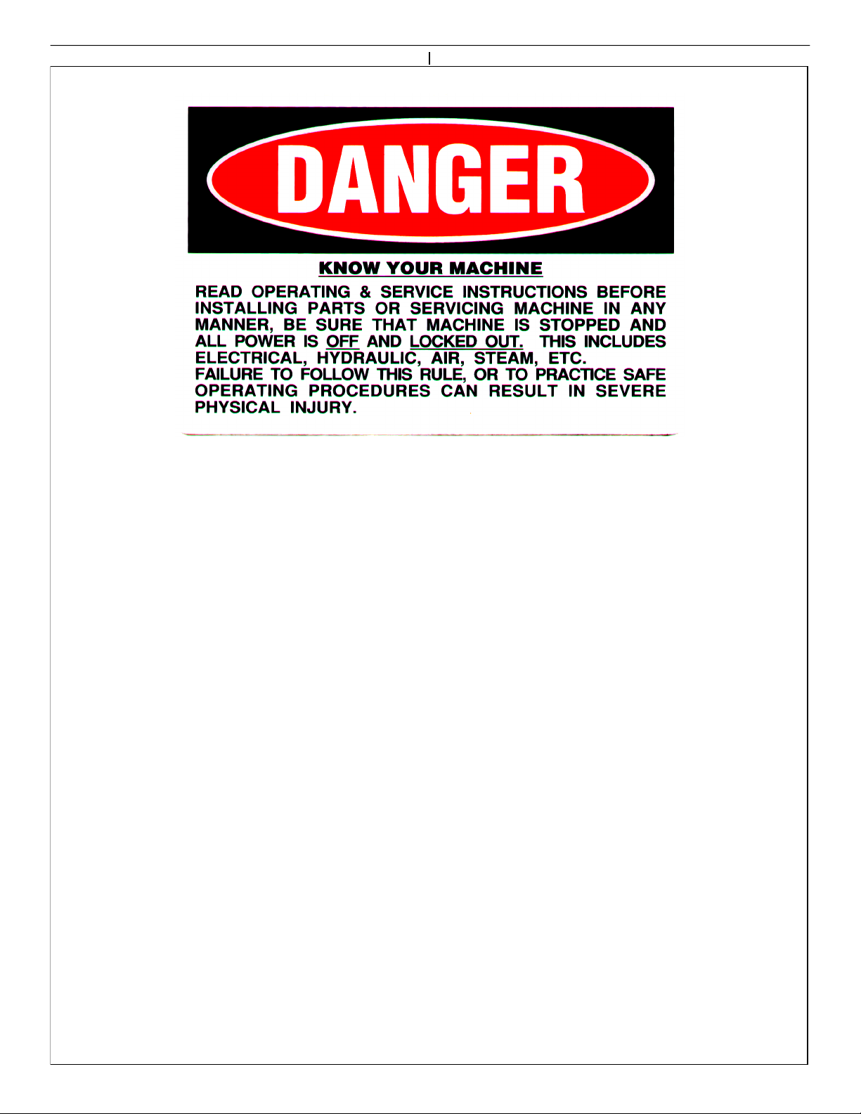
LISTED BELOW IS THE DEFINITION OF THE HAZARD
LEVEL USED ON THE SAFETY STICKERS.
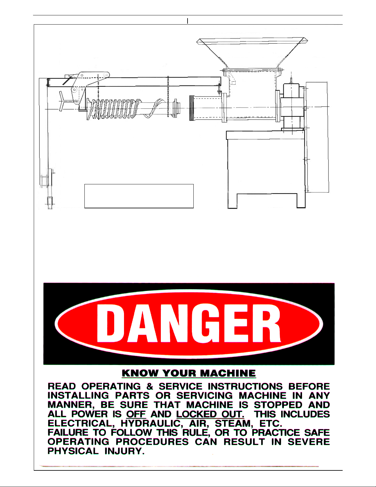
TYPICAL DIXIE GRINDER
FRAME
MOTOR
COVER
PANELS
SERIAL
NUMBER
HOPPER
RING
BELT
GUARD
HEAD
GEARBOX
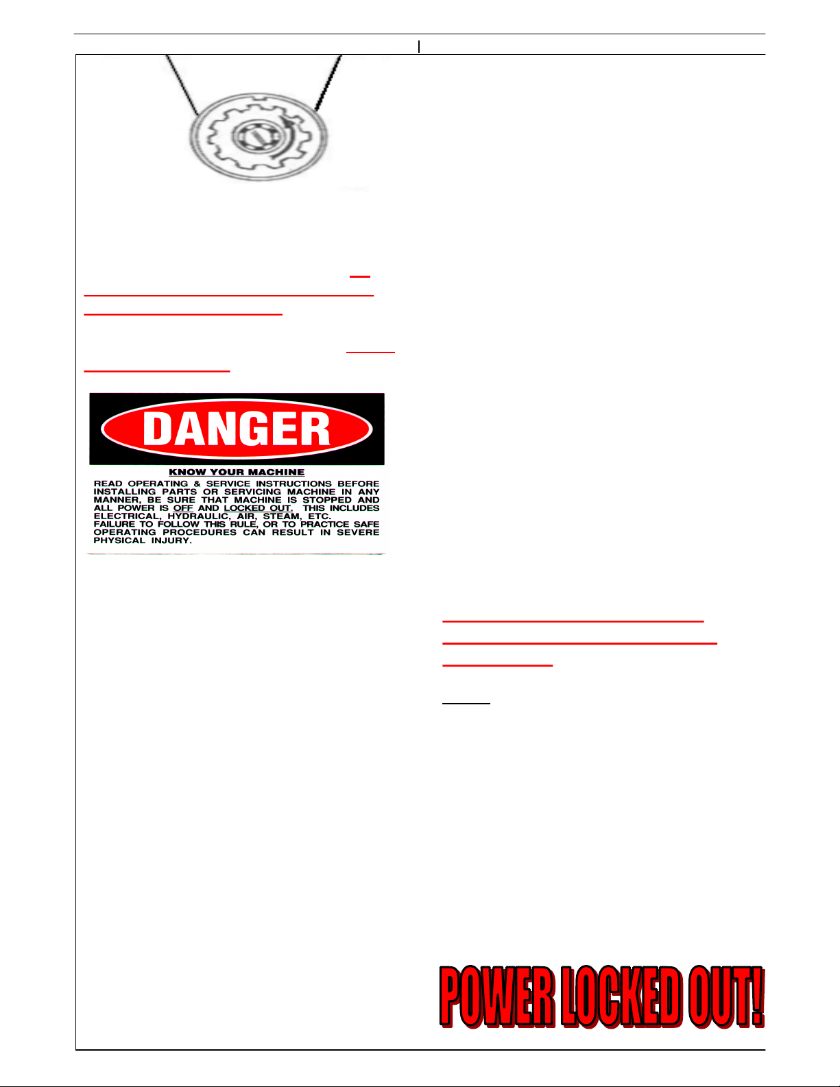
SAFETY TAG
ORIFICE
PLATE
GUARD
GEARBOX
TAG
3
INTRODUCTION
A Grinder Unit is a type of size reduction
machine. Its primary purpose is to grind meat,
meat by-products, and other similar products.
The primary grinding components are a plate
retaining ring, orifice plate, plate bushing,
knifeholder with knife inserts, centering pin,
spring or springs, head, feedscrew, hopper,
gearbox, and drive pulleys. In most instances
an electric motor drives the grinder unit.
This unit is mounted on a undermount frame
(as shown on cover) or sidemount frame.
Standard safety equipment includes a belt
guard, a hopper guard, and a plate guard. If a
transition funnel is used, the plate guard is not
required.
It is important that your application, and/or
installation does not render these guards
ineffective. If for any reason you believe these
guards are not adequate, do not use the machine
and call Dixie Grinders Inc. at once. (256) 582-
0477 OR (800) 745-0586.
This machine was sold for a specific application.
If you are not familiar with the application that
this unit was sold for, check with Dixie Grinders
Inc. before using the machine.
All operators and sanitation personnel should
read this manual and understand it.
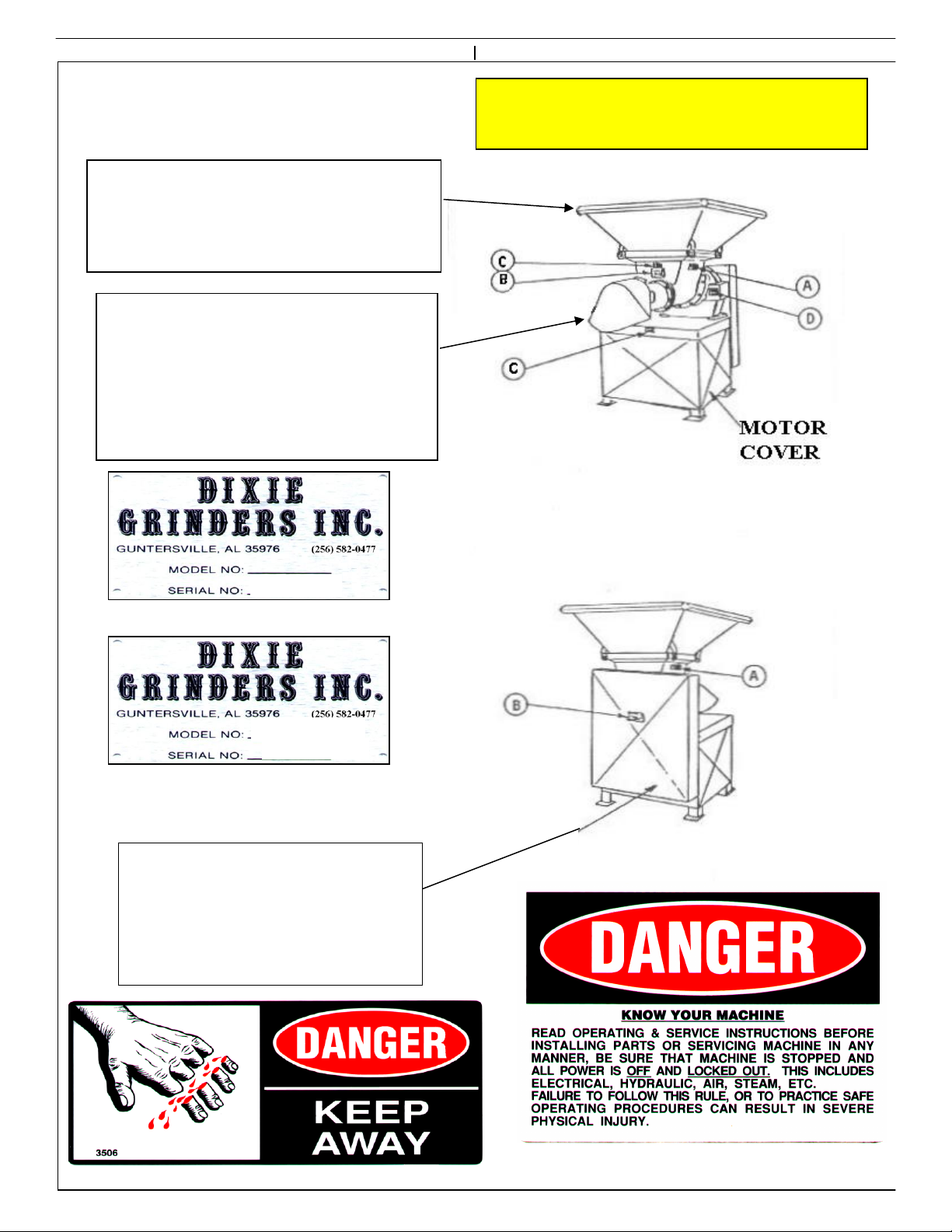
TAG D 1 EA. (ON GEARBOX)
TAG C 2 EA. (ON FRONT OF
HOPPER AND FRONT OF FRAME)
TAG B 2 EA. (ON BELT GUARD
TAG A 2 EA. (ON SIDES OF HOPPER) AND ON HOPPER FRONT) 4
THE HOPPER GUARD AND PLATE
GUARD MAY NOT BE ATTACHED
FOR SHIPPING!
THE HOPPER GUARD IS
PROVIDED TO RESTRICT
ACCESS TO THE ROTATING
FEEDSCREW!
THE PLATE GUARD IS
PROVIDED TO RESTRICT
ACCESS TO THE PLATE, THE
KNIFEHOLDER, AND THE
FRONT END OF THE
FEEDSCREW!
THE BELT GUARD IS
PROVIDED TO RESTRICT
ACCESS TO THE V BELTS
AND THE ROTATING
PULLEYS!
FAILURE TO USE GUARDS WHILE THE
GRINDER UNIT IS IN OPERATION MAY
RESULT IN SEVERE INJURY OR DEATH!
REPLACE SAFETY TAGS WHEN
NECESSARY! CALL DIXIE GRINDERS
INC. FOR REPLACEMENT SAFETY TAGS.

SITE CONSIDERATIONS:
It is important that the permanent position of
the grinder unit provides clearance of several
feet behind, to either side, and approximately
eight feet or more in front of the grinder unit.
If the grinder is set on a stand, or leg extensions
are attached, an adequate platform must be
provided to provide safe access to the grinder
unit. It will be necessary to have an approved
platform or device to provide access so the unit
can be properly sanitized, disassembled,
assembled, and maintained. Consideration must
be given to allow for complete service to the
grinder unit.
Platforms should be so designed not to make
the hopper guard, or other guarding, ineffective.
The hopper guard is not a hopper for holding a
large amount of material, it is designed to keep
the operator away from the feedscrew. If the
location of this grinder unit compromises this
feature, special guarding may be necessary.
Consult your Safety Engineer, Plant Engineer,
and O.S.H.A. for all regulations related to the
guarding of this machine.
Only the feedscrew puller and ring lift can be
attached to the grinder unit directly. Do not use
the grinder frame to support other equipment
without prior approval from Dixie Grinders Inc.
The grinder frame is not to be used as a
personal stand, and under no circumstances
should anyone be allowed to climb on it or use it
as a platform. Remember to Work Safely!
"THE GRINDER HAS ARRIVED"
LIFT EQUIPMENT REQUIRED:
We recommend using a 8,000 pound or greater
capacity fork lift with 60" or longer forks. Do
not attempt to unload the grinder unit from a
commercial van from ground level! Only
authorized and properly trained equipment
movers should attempt to unload the grinder
unit. Remember to Work Safely!
PRE-UNLOADING INSPECTION:
Before the grinder unit is unloaded, inspect the
unit for any damage before unloading. If the
machine is damaged consult your management,
the trucking company, and Dixie Grinders Inc.
before unloading the machine!
UNLOADING GRINDER UNIT:
With the commercial van properly chocked and
secured to the loading dock, and using only
approved and adequate dock plates should any
attempt be made to unload this machine. Lift
only under the grinder frame, never attempt to
pick up a grinder from the hopper or gearbox.
The forks should be long enough to extend
beyond the end of the frame a safe distance.
Unload the grinder unit and all parts that have
been shipped with the grinder unit. Consult the
packing slip to insure that all pieces have been
unloaded.
UNPACKING:
When the grinder has been properly unloaded it
should be placed in a suitable location for
unpacking. The belt guard protector and the
shipping skids may be removed. Remove any
spare parts that may have been shipped in the
grinder hopper. Use appropriate equipment
and appropriate personal safety equipment in
this process. Remember to Work Safely!
5

UNIT CONTROLS.
Dixie Grinders Inc. does not supply motor
controls, starters, stop/start stations,
disconnects, or other related equipment that is
required to control the function of the grinder
unit.
INSTALLATION:
The machine can be installed in its permanent position
after the skidding has been removed. Use only
adequate equipment and properly trained personnel to
install the grinder in its permanent position. Use great
care in moving this equipment, it is heavy and must
not be tipped, tilted, jarred or jammed into position.
We recommend a 1°slope to allow water to drain from
the grinder unit.
We recommend serious consideration is given to
the location of the start/stop station.
We strongly recommend that additional stop
stations are located where deemed appropriate.
Disconnects that can be locked out should be so
located that employees that have to operate,
service, and sanitize the unit can lock the unit
out. Each employee that has to work on this
machine should be given a lock and key and
trained in proper procedures for LOCK
OUT/TAG OUT!
Please consult with your Safety Engineer, your
Electrical Engineer, and O.S.H.A. for all
regulations related to the controls and wiring
for this machine.
We do not recommend the use of wye-delta or
star delta starters. In some areas this is
required. If your machine must be wired this
way the operators must understand that they
cannot begin to grind product until full power is
supplied to the grinder feedscrew. If there is
product in the grinder hopper before the unit is
turned on, the grinder may not have enough
torque to start grinding in the reduced torque
condition.
Frequency controllers are very useful, but with
the exception of a grinder connected directly to
a pump unit or mechanical deboner, the use of a
frequency controller on a grinder unit is usually
not necessary. We do recommend a frequency
controller or some form of speed control is used
to feed the grinder, and often to take the
product away from the grinder.
We do not recommend remote operation of any
grinder unit unless special precautions are
taken, and that all possibilities of employee
injury are eliminated.
6
DISASSEMBLY TOOLS:
If the grinder is not located on floor level
make no attempt to disassemble the grinder
unit without an adequate platform or
provisions provided by the installation
contractor, plant engineer, or plant safety
officer. The grinder has many parts that
have square edges and cutting edges.
Adequate safety equipment should be used at
all times!
After the grinder has been installed in its
permanent position, it can be disassembled.
Plate Lifter
This is used to
remove the plate
and bushing from
the grinder unit, or
on assembly to
install the plate and
bushing into the
grinder unit.
GRINDER UNIT DISASSEMBLY:
When the grinder unit has been properly
secured, disassembly can begin.
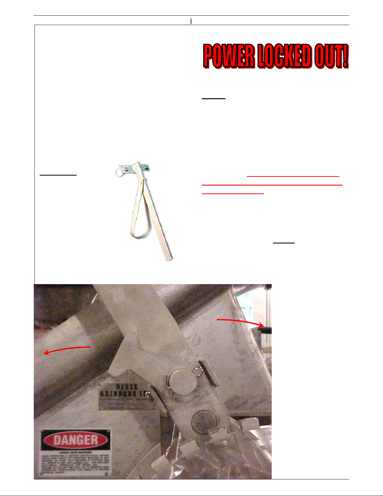
Step 1. Use the Ratchet Assembly to remove
the ring. The Ratchet Assembly is shown in
the locked position for grinder operation.
To use the Ratchet Assembly, with the Power
Locked out, support the handle with one
hand, and slide the lock toward the grinder
hopper. This will realease the ratchet dog.
Using the Ratchet lever and ratchet dog to
push the ring counter-clockwise to loosen the
grinder ring. When the ring can be turned
by hand, return the ratchet lever and dog to
the locked position.
OFF
ON
Step 2. When the ring
has been loosened turn
it off by hand.
Depending on the ring
type, the ring may
weigh 100 lbs. or more.
If this is more than you
can lift, get help! Use
the ring remover if
your machine has been
equipped with one. Do
not attempt to remove
the ring if you are out
of position, or if the
ring is higher than the
center of your chest, or
if you cannot lift this
much on your own!
Do not bang the ring
threads against the
centering pin!
7

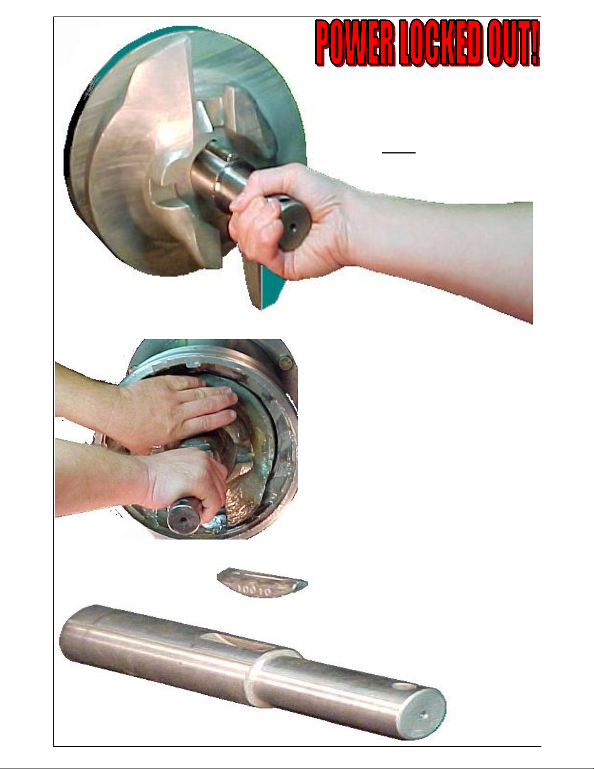
Step 3. PLATE REMOVAL:
Using the plate lifter, remove the plate and
bushing from the grinder unit. It is
necessary to lift while pulling on the bushing.
Do not use screwdrivers or other tools to pry
the plate from the grinder unit.
Step 5. REMOVE SPRINGS: Remove the
Belleville springs, 2 each. Some pins have a
spacer collar behind the Belleville springs, if
this collar is used, remove it also.
8
Step 4. KNIFEHOLDER REMOVAL:
Remove the knifeholder from the face of the
grinder. The knife inserts are sharp, so wear
appropriate gloves.
OUTWARD
FACING
SPRING
INWARD
FACING
SPRING
Step 5 continued. The hand is removing the
#2938 springs, notice that these also have one
spring facing inward and one facing out.
Step 6. Remove the #2937 spacer collar.
It may be necessary to hold the feedscrew in
while pulling the pin out.
Wash out the pin hole after removing the pin in
preperation of using the FSP2006 Feedscrew
Puller.
9
Step 7.
REMOVE THE
CENTERING PIN
Do not loose the pin key when you
are removing the pin!
MODEL FSP2006 FEEDSCREW
PULLER
10
With the feedscrew removed from the grinder unit, it can now be wired. Dixie Grinders Inc.
does not supply motor controls, disconnects, or stop/start stations. Please consult your
Electrical Engineer, your Safety Engineer, OSHA, and other Federal, State, and local
regulations.
ROTATION: When the grinder unit has
been disassembled, and then wired
according to all applicable codes and
regulations, rotation can be checked. Do
not turn the unit on until you are positive
that no one is in harms way! The grinder
feedscrew should turn counterclockwise!
After the rotation has been checked LOCK
OUT THE POWER!
SANITATION: Appropriate clothing should
be worn, and all safety precautions should be
taken before cleaning any equipment.
Typical grinder units have tin plated
feedscrews, heads, rings, and often the
grinder hopper is also tin plated. Before you
begin to clean your machine, make sure any
commercial cleaning agents are approved for
cleaning tin plated surfaces. If no mention
of tin is on the label but the cleaner is not
recommended for aluminum do not use it
unless you have contacted the cleaner
manufacturer for their recommendations.
Do not use high pressure streams of water to
clean a grinder unit. It is possible to drive
water past the oil seals and damage the
gearbox.
Do not allow any cleaning agent to sit on the
tin plated surfaces for an extended period of
time. Apply the soap, and rinse it off
immediately!
After cleaning, rinse the unit with large
quantities of hot water. We strongly
recommend drying the unit and applying a
liberal amount of mineral oil to all tin plated
surfaces. If the machine is not going to be
used for an extended period, apply a coat of
edible grease to all surfaces and wrap the
grinder in plastic.
SANITIZERS: Iodine sanitizers. Iodine
reacts with tin. If the Iodine is in sufficient
strength and has been on the tin plated
surfaces long enough it will turn anything
that touches the surface deep purple. Other
sanitizers also may react with tin plated or
stainless steel surfaces. Check label
instructions before using. If you notice that
the tin plating is coming off of your grinder
unit contact Dixie Grinders Inc.
UNIT ASSEMBLY: Please study all of the
grinder parts shown on the exploded view
before you attempt to assemble the grinder
unit. The exploded view is at the rear of the
maintenance instructions. (These instructions
assume that the grinder unit has not been
disassembled any further than the instructions already
given.)
MAKE SURE THE POWER IS
STILL LOCKED OUT BEFORE
ASSEMBLY.
Step 1. INSTALL FEEDSCREW.
Using the Model FSP2006 feedscrew puller,
or other device, install the feedscrew into the
grinder unit. Do not attempt to install the
feedscrew by hand, or by yourself. You will
notice that when using the FSP2006 the
feedscrew usually engages on the drive spline
with little effort.
11
12
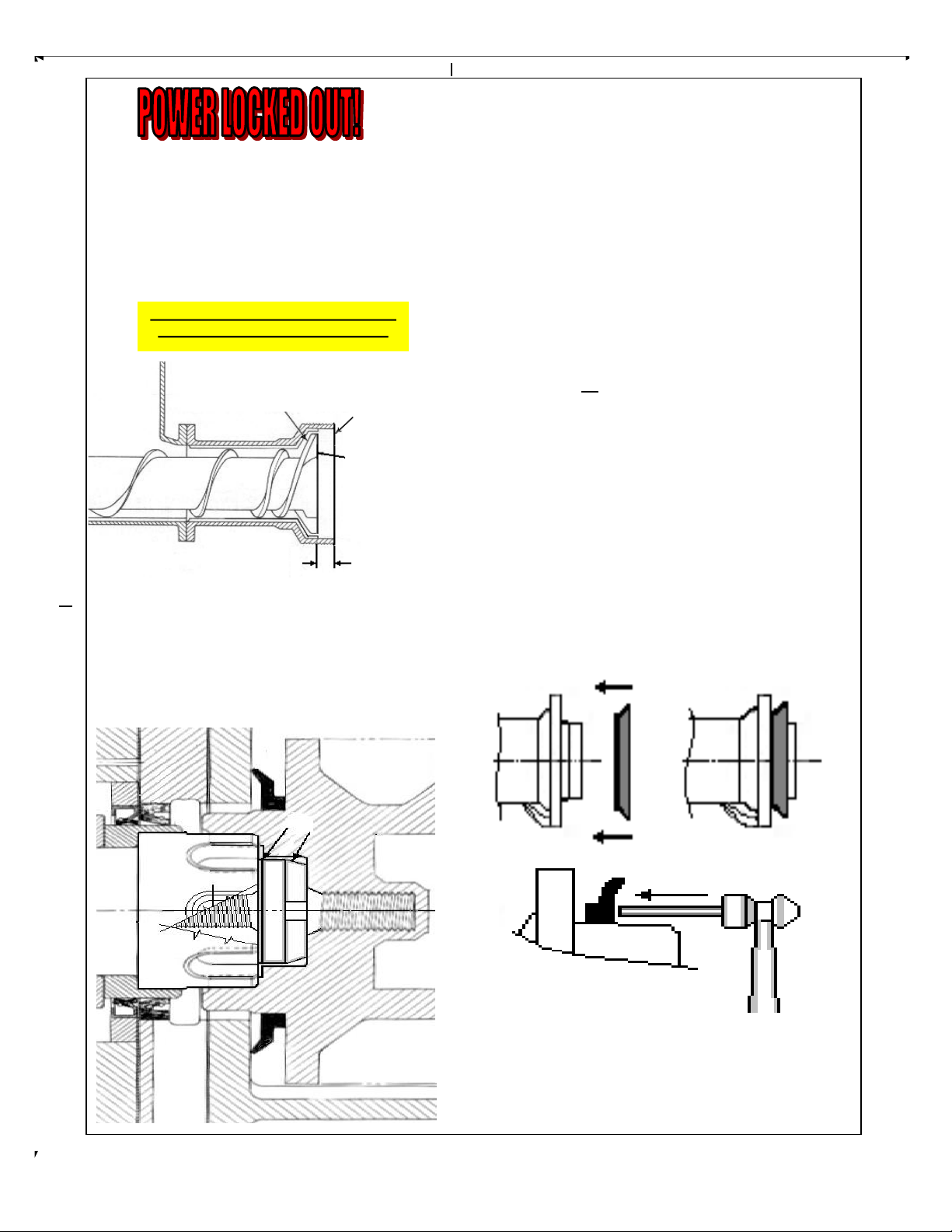
3/4"
FEEDSCREW
HEAD
The head space should be checked on a weekly
basis. The head space is 3/4" on all DGI
grinder units. This should be done with the
excluder seal removed. Spacers should be
added if the measurement is more than 3/4".
Spacers should be removed if less than 3/4".
NOTE: THE FEEDSCREW SHOULD
NEVER RUB THE HEAD FLUTES!
If the feedscrew does not slide up on the
spline, it may be necessary to push down and
in, while turning the feedscrew slightly to
engage the drive spline. Never reach into the
hopper to engage the drive spline. The
feedscrew will jump in another inch when it
is seated on the spline. Check the head
HEAD SPACE ADJUSTMENT.
Item 1 is our Adjustment Washer Part# 1615
(1/16" thick) and/or Adjustment Washer Part
Number 1614 (1/8" thick). These are used with the
Thrust Screw Part# 1468 (Item 2). Add or
subtract washers to obtain the 3/4" head space
dimension.
Note: In the illustration the Thrust Screw is shown
mounted in the hole in the mainshaft. If the
threads in the main shaft fail, or a thrust screw
breaks off and removal is not possible, threads
have been provided in the feedscrew hole.
Obviously, the Thrust Screw should be installed in
the main shaft or the feedscrew, not both.
NOTE: This step is necessary when changing
feedscrews, heads, hoppers, or if the gearbox has
been rebuilt. Failure to set the proper head space
may result in serious damage to the unit. If the
feedscrew is allowed to rub the head, metal
particles may contaminate your finished product!
When the Head Space has been adjusted, remove
the feedscrew so that the Unit can be assembled for
operation.
Remember the excluder seal should not be on the
feedscrew when adjusting the head space.
Installation of excluder seal. Please note the
direction, the lip is suppose to touch the face
of the hopper! See drawing above.

13
Step 2. Install the #2936 Pin Key in the #2935 Pin
2936 Pin Key
2935 Pin
Step 3. Install the #2935 Pin with the #2936 Pin Key installed into the feedscrew. Do not beat the
pin into position, reposition the key, and try again. Beating the pin into position will insure that you
will never get the pin out! The pin with the key in position should simply slide in and out.

Step 4. Install
the #2937 spacer
collar over the
pin. This part
can go in either
side up.
When these springs are new the
uncompressed height of the two springs is
over 1/4" as shown above. This is how they
are to be installed, touching at the center, a
gap at the outside. One spring facing in, one
facing out.
Step 5. Install the #2938 springs. The first spring
install facing inward, the second spring facing
outward. No exceptions, not just on Thursday,
every time.
14
15
Insert locating pin.
Step 7. INSTALL KNIFEHOLDER
Install the Knifeholder into the grinder.
Inserts face to the outside. You won't believe
how many operators put them in backwards!
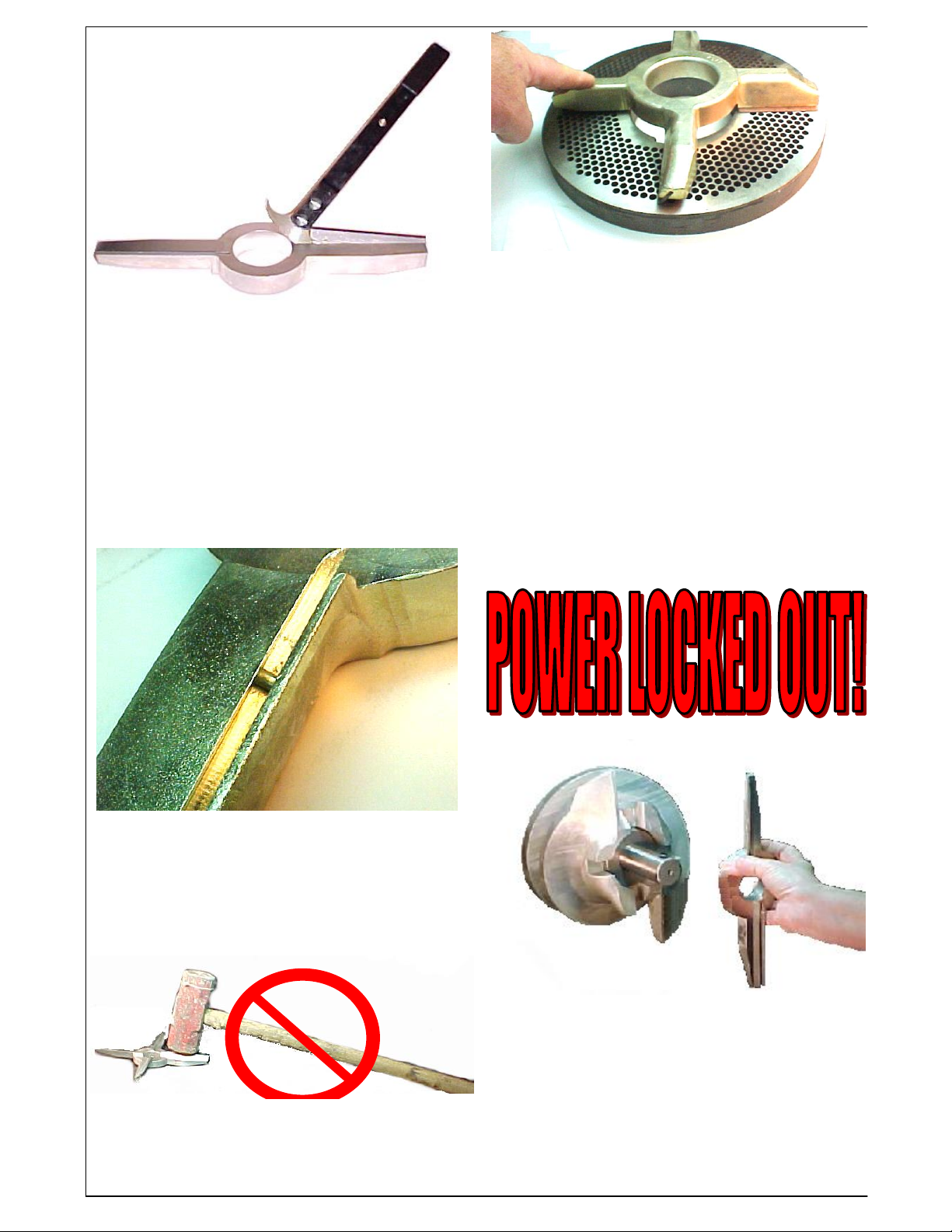
Step 6. Replace the #1155 inserts in the
#2930 knifeholder. Use the insert removal
tool #10315 shown above. Do not drive the
inserts out from the outside edge, you will
shear the pins that locate the knife inserts.
Use a soft mallet, a block of soft wood or soft
plastic to tap the inserts in place.
Do not use a steel faced hammer!
Check the knifeholder for flatness after the
inserts are installed, it should not rock.
Knifeholders that rock do not work. If there
is any clearance, a few thousands of an inch,
it may be at the center of the knifeholder.
Clearance at the outside will cause the
grinder to fail to function. Ok, I know a 4-
bladed knife is shown and you are using a 2-
bladed knife, it still has to sit flat.
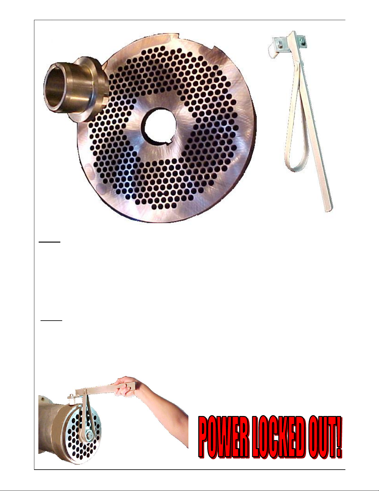
Plate Lifter
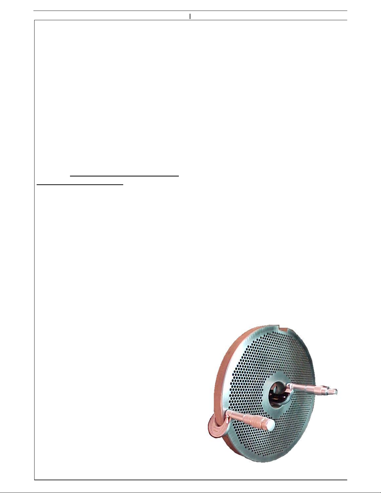
Step 9. Install plate and bushing. Place plate-bushing combination over the end of the pin.
Slide the plate toward the grinder head. Using the plate lifter, lifting on the bushing, slide the
plate and bushing into the machine. Yes the feedscrew is heavy and some effort is required to
do this. If the plate and bushing slide into the grinder easily, something is wrong!
16
Step 8. Install bushing in plate. Lubricate the inside of the bushing with an edible lubricatant.
If you don't know which one to use, contact your quality control department, management, or
maintance. Failure to do so can cause the bushing to seize to the pin! It is also a good practice
to apply a light coating of edible lubricant to the inside surface of the plate (the side that runs
against the insert). This helps to keep the plate cool until product arrives at the plate.

Using the ratchet assembly, pushing on the lever, tighten the ring until tight, it does not need
to be so tight that you are about to tip the machine over, just snug. When snug, flip the
ratchet pawl over, and losen the ring 1/8" turn. Return ratchet lever and pawl to the lock
position.
Step 11. Install
Ring. The grinder
ring is heavy. Use
the RL2000 ring
lift if you have one,
or get help to
install the ring.
Once started on the
threads, turn
clockwise until
hand tight.
OFF
ON
Step 10. If you have not already done so, retun the ratchet lever pawl and lever to the locked
postion. This keeps the pawl from getting into your way when putting the ring on.
17

18
GRINDER PLATES.
The orifice plate is probably the most
important single part of a meat grinder.
Dixie Grinders Inc. sells only "PREMIUM"
type tool steel plates. Extensive testing has
shown time and time again that our selection
of tool steel performs the best over the entire
range of products ground. Our special heat
treatment process, which includes a soak at -
300°F for two hours, gives our plates the
toughness that we have found is required.
Other steels may stay sharper, but when it
breaks into ten pieces its sharpness is no
longer an advantage.
Failure to change the pin and bushing
shortens the life of the feedscrew and the
head. When the pin and bushing become
worn they allow the feedscrew to contact the
head. This results in rapid wear to the
feedscrew and head, and can even lead to
metal in the finished product.
.500
+.000
-.002
MAINTENANCE INSTRUCTIONS:
GRINDER RING.
The grinder ring needs little maintenance
other than thread inspection. The center
support should contact the slip in bushing at
the same time that it contacts the plate. If
there is any clearance between the plate
bushing and the center support after the ring
has been tightened first inspect the plate for
flatness, see page 15. If the plates are flat, or
within .002 per side of being flat, send the
ring in for rebuilding. If foreign material
causes a plate to break, inspect the ring
before use. The center support sets back .500
+.000/-.002
PLATE BUSHING.
The plate bushing supports the weight and
the side load of the feedscrew. Being a plain
bearing it relies on the product for
lubrication and cooling. The bushing is mild
steel and carburized. The hardness is only
.040 deep, and some of this is used during the
honing after the bushing has been hardened.
Therefore we recommend to discard the
bushing when it measures 2.665 ID. Typical
wear is very even. Checking or grooves
indicate that the machine is run empty often.
Normal life is about one month.
Plates continued. (This inspection is
performed with the plate out of the machine.)
Sharp plates may cut you, be careful!
Inspect the plate before each use. Inspect the
edge of the holes, they should form sharp
corners. The plate should be clean.
Check for discolored plates, do not use a
plate with a deep blue coloring between the
holes. Check for cracks, especially between
the holes. If cracks are present, do not use
the plate. Check for grooves, broken holes,
and any other defect. Do not use defective
orifice plates. The plate must be 3/4" thick
or thicker.
We recommend that a fresh plate surface
should be used every 8 hours of operation.
Operations that run empty or with hard to
grind materials may have to change plate
surfaces more often.
Grinder Plates should be sharpened with a
vertical type surface grinder, typically called
a "Blanchard Type". With this type of
surface grinder the plate should be placed
directly over the center of the table. We do
not recommend sharpening the plates when
they are placed out on the table, not directly
over the center of the table.
If you have a Pieco or Van Norman surface
grinder we recommend using our grinding
wheels to sharpen the plate. These
specialized grinding wheels produce the
correct surface finish to provide clean, cool,
cutting. Plates that are not sharpened
correctly will not grind even the softest of
meats. The plates must be flooded with
coolant when they are ground. The
horsepower rating of your surface grinder
will determine feed rate. The plate should be
sharpened enough to restore the edge of the
hole, and remove any discoloration from
running empty (see Maintenance
Instructions, Grinder Plates). Nicks and
gouges should be ground out.
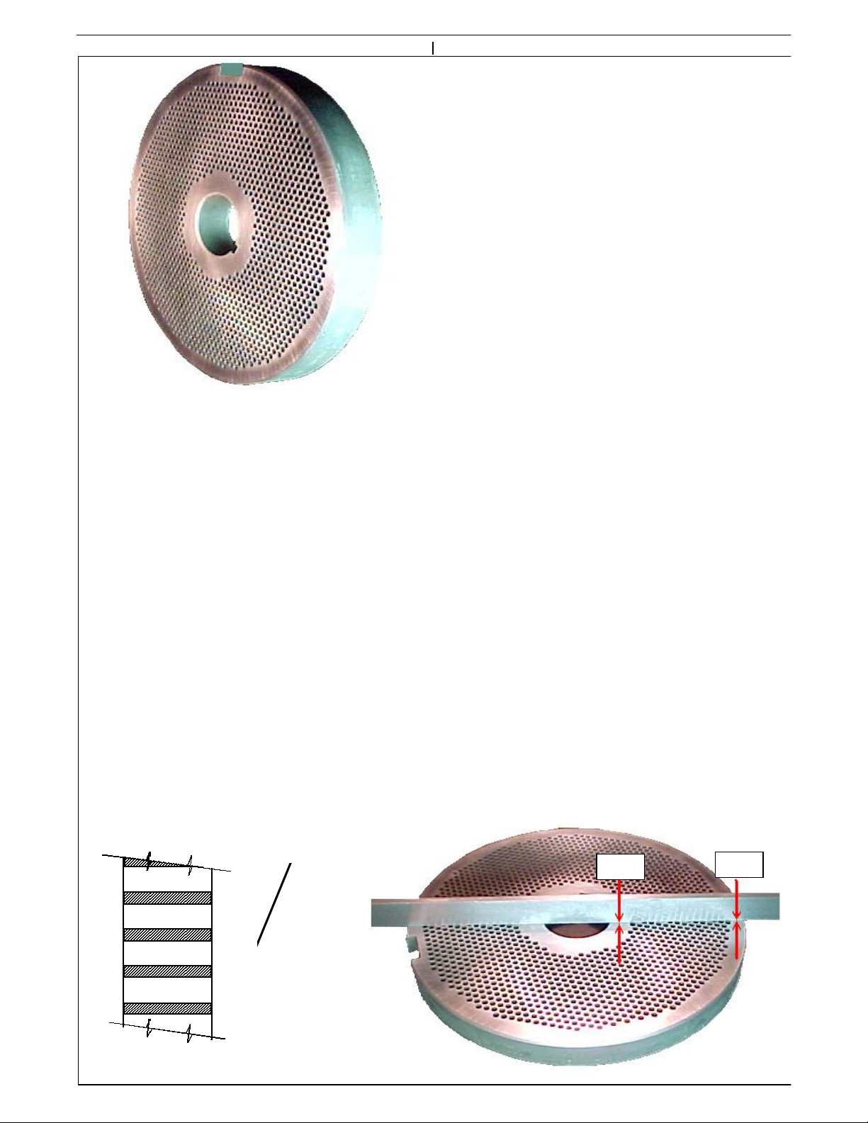
The plates should be ground perfectly flat, or
slightly concave, .002 per side max.
We offer a factory modified Van Norman
surface grinder to our customers. This
machine sharpens the plates quickly and
properly.
Improperly sharpend plates is the most
common grinder problem.
SHARP
CORNER
19
.000
.002
A majority of all service calls eventually
point to the customers real problem, dull
plates. Next to plate sharpness, plate
flatness is important. Grinder plates should
be ground flat, or slightly concave. Using a
precision straight edge and feeler gauges the
amount of concave can be determined (see
page 15). Plates that are ground convex will
not work properly. The knife inserts will
not seat at the outer edges of the plate, and
the product will not be cut cleanly.
The plates also must be uniform in
thickness. If the bearings in the table of
your surface grinder are worn, it is possible
that the plates will not be uniform. Using a
micrometer, measure around the outside
edge of the plate, there should be less than
.0005 variation. Measure around the inside
diameter also, this should also show less than
.0005 variation. If the measurements are
consistently less at the inside diameter than
at the outside diameter you also may assume
that the plate is concave, and if thicker it
may be convex. It is rare that a plate would
be convex on one side and concave on the
other, but measuring with a ground straight
edge and feeler guages is the best test for
flatness.
20
If your plates are turning blue, the operators
are running the grinder empty. The blue
color indicates temperatures up to 600°! This
is above the draw temperature of this steel,
and unless the heat affected zone is removed
this plate will crack. Under careful
examination you may be able to determine
how deep the discoloration is by looking
down the holes. We recommend removing
this layer, plus .030! Plates with cracking
between the holes can be attributed to this
condition 99% of the time.
The most important feature, however, is
sharpness. Most people think that a grinder
plate should shine like a mirror, the fact is
that a certain amount of roughness is
required. The roughness of the plate is what
keeps the the inserts sharp. We supply a
specially manufactured grinding wheel that is
36 grit, rather than the 60 or 80 that other
companies sell. The grains themselves should
be soft and what is called friable, that is when
dull, it should leave the wheel. If you buy a
good knife, you sharpen it with a very soft
stone. These plates are harder and tougher
than a knife blade, therefore it only makes
sense to sharpen it with a soft stone. Dress
the wheel before sharpening each plate. Do
not let the wheel spark out, when the plate is
sharp, get the wheel off the plate!
Other DIXIE GRINDERS Grinder manuals

DIXIE GRINDERS
DIXIE GRINDERS 16-10 User manual

DIXIE GRINDERS
DIXIE GRINDERS 7-7 User manual

DIXIE GRINDERS
DIXIE GRINDERS 11-7 User manual

DIXIE GRINDERS
DIXIE GRINDERS 11-10 User manual

DIXIE GRINDERS
DIXIE GRINDERS 11-10 User manual

DIXIE GRINDERS
DIXIE GRINDERS 8-7B User manual

DIXIE GRINDERS
DIXIE GRINDERS 12-10 User manual

DIXIE GRINDERS
DIXIE GRINDERS 11-7 User manual


