DIXIE GRINDERS 8-7B User manual

DIXIE GRINDERS INC.
1324 RAILROAD AVENUE GUNTERSVILLE AL 35976
(800) 745-0586 (256) 582-0477 FAX (256) 582-0478
MODEL 8-7B
GRINDER UNIT
SAFETY INSTALLATION OPERATION MAINTENANCE
THIS MANUAL MUST BE READ TO,
OR BY EACH PERSON, BEFORE
THAT PERSON OR DEPARTMENT
UNCRATES, OPERATES,
MAINTAINS, OR SUPERVISES USE
OF THIS MACHINE IN ANY WAY.
CAUTION

2
IMMEDIATE HAZARDS
WHICH WILL RESULT IN
SEVERE PERSONAL INJURY
HOPPER GUARD
LISTED BELOW IS THE DEFINITION OF THE HAZARD
LEVEL USED ON THE SAFETY STICKERS.
TYPICAL DIXIE 8-7 GRINDER UNIT
FRAME
MOTOR
COVER
PANELS
SERIAL
NUMBER
HOPPER
RING
BELT
GUARD
HEAD
GEARBOX
SAFETY TAG
ORIFICE
PLATE
GUARD
GEARBOX
TAG

3
INTRODUCTION
A Grinder Unit is a type of size reduction
machine. Its primary purpose is to grind meat,
meat by-products, and other similar products.
The primary grinding components are a plate
retaining ring, orifice plate, plate bushing,
knifeholder with knife inserts, centering pin,
spring, feedscrew, hopper, gearbox, and drive
pulleys. In most instances an electric motor
drives the grinder unit.
This unit is mounted on a undermount frame
(as shown on cover) or sidemount frame.
Standard safety equipment includes a belt
guard, a hopper guard, and a plate guard. If a
transition funnel is used, the plate guard is not
required.
It is important that your application, and/or
installation does not render these guards
ineffective. If for any reason you believe these
guards are not adequate, do not use the machine
and call Dixie Grinders Inc. at once. (256) 582-
0477 OR (800) 745-0586.
This machine was sold for a specific application.
If you are not familiar with the application that
this unit was sold for, check with Dixie Grinders
Inc. before using the machine.
All operators and sanitation personnel should
read this manual and understand it.

TAG D 1 EA. (ON GEARBOX)
TAG C 2 EA. (ON FRONT OF
HOPPER AND FRONT OF FRAME)
TAG B 2 EA. (ON BELT GUARD
TAG A 2 EA. (ON SIDES OF HOPPER) AND ON HOPPER FRONT) 4
THE HOPPER GUARD AND PLATE
GUARD MAY NOT BE ATTACHED
FOR SHIPPING!
THE HOPPER GUARD IS
PROVIDED TO RESTRICT
ACCESS TO THE ROTATING
FEEDSCREW!
THE PLATE GUARD IS
PROVIDED TO RESTRICT
ACCESS TO THE PLATE, THE
KNIFEHOLDER, AND THE
FRONT END OF THE
FEEDSCREW!
THE BELT GUARD IS
PROVIDED TO RESTRICT
ACCESS TO THE V BELTS
AND THE ROTATING
PULLEYS!
7.1E
220
8-7B
09-028
FAILURE TO USE GUARDS WHILE THE
GRINDER UNIT IS IN OPERATION MAY
RESULT IN SEVERE INJURY OR DEATH!
REPLACE SAFETY TAGS WHEN
NECESSARY! CALL DIXIE GRINDERS
INC. FOR REPLACEMENT SAFETY TAGS.

SITE CONSIDERATIONS:
It is important that the permanent position of
the grinder unit provides clearance of several
feet behind, to either side, and approximately
eight feet or more in front of the grinder unit.
If the grinder is set on a stand, or leg extensions
are attached, an adequate platform must be
provided to provide safe access to the grinder
unit. It will be necessary to have an approved
platform or device to provide access so the unit
can be properly sanitized, disassembled,
assembled, and maintained. Consideration must
be given to allow for complete service to the
grinder unit.
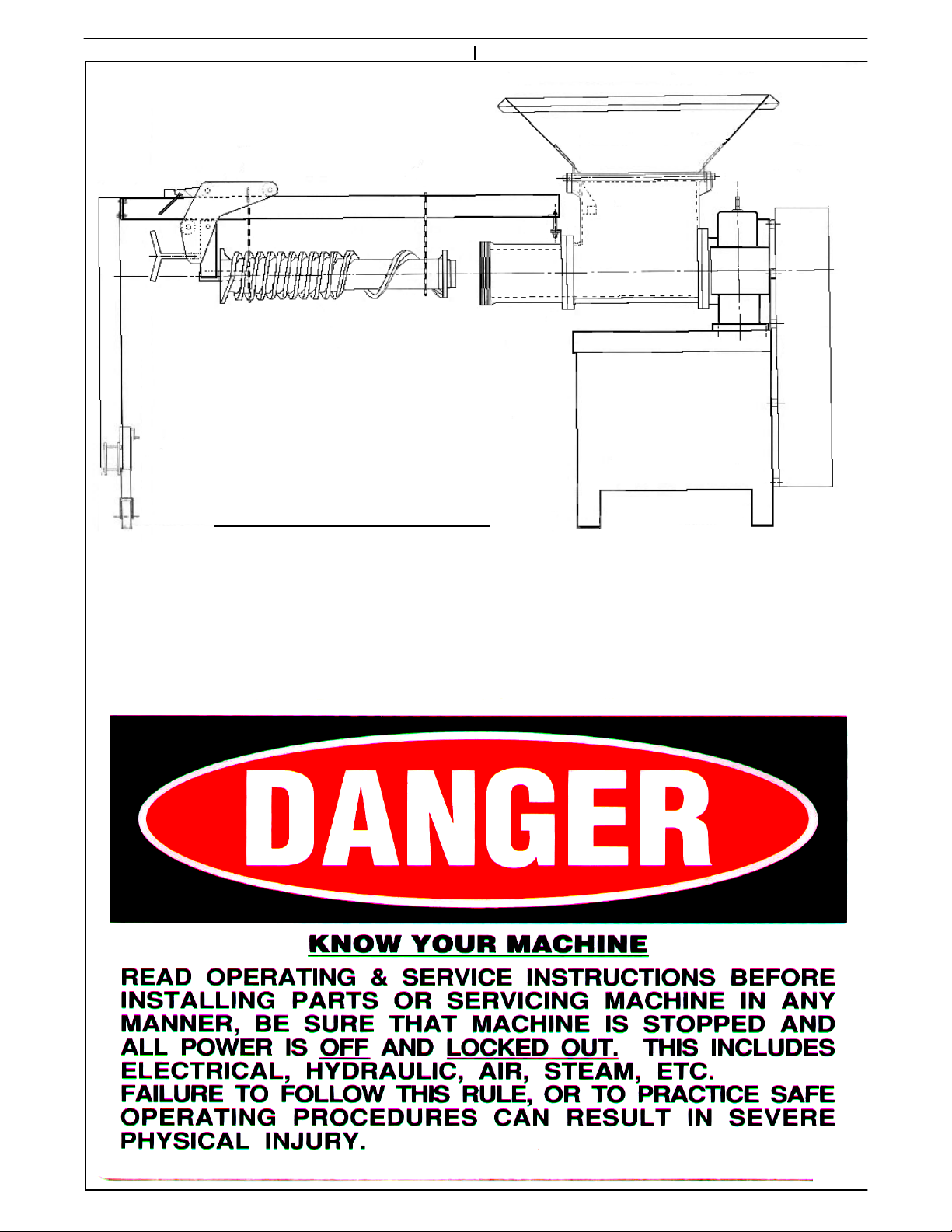
Platforms should be so designed not to make
the hopper guard, or other guarding, ineffective.
The hopper guard is not a hopper for holding a
large amount of material, it is designed to keep
the operator away from the feedscrew. If the
location of this grinder unit compromises this
feature, special guarding may be necessary.
Consult your Safety Engineer, Plant Engineer,
and O.S.H.A. for all regulations related to the
guarding of this machine.
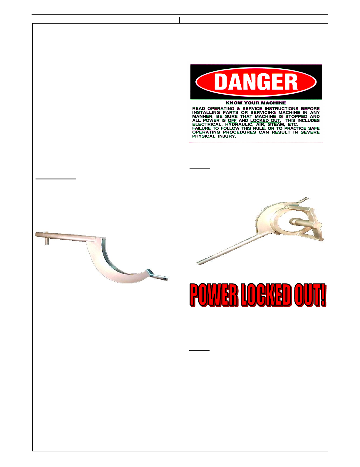
Only the feedscrew puller and ring lift can be
attached to the grinder unit directly. Do not use
the grinder frame to support other equipment
without prior approval from Dixie Grinders Inc.
The grinder frame is not to be used as a
personal stand, and under no circumstances
should anyone be allowed to climb on it or use it
as a platform. Remember to Work Safely!
"THE GRINDER HAS ARRIVED"
LIFT EQUIPMENT REQUIRED:
We recommend using a 5,000 pound capacity
fork lift with 48" or longer forks. Do not
attempt to unload the grinder unit from a
commercial van from ground level! Only
authorized and properly trained equipment
movers should attempt to unload the grinder
unit. Remember to Work Safely!
PRE-UNLOADING INSPECTION:
Before the grinder unit is unloaded, inspect the
unit for any damage before unloading. If the
machine is damaged consult your management,
the trucking company, and Dixie Grinders Inc.
before unloading the machine!
UNLOADING GRINDER UNIT:
With the commercial van properly chocked and
secured to the loading dock, and using only
approved and adequate dock plates should any
attempt be made to unload this machine. Lift
only under the grinder frame, never attempt to
pick up a grinder from the hopper or gearbox.
The forks should be long enough to extend
beyond the end of the frame a safe distance.
Unload the grinder unit and all parts that have
been shipped with the grinder unit. Consult the
packing slip to insure that all pieces have been
unloaded.
UNPACKING:
When the grinder has been properly unloaded it
should be placed in a suitable location for
unpacking. The belt guard protector and the
shipping skids may be removed. Remove any
spare parts that may have been shipped in the
grinder hopper. Use appropriate equipment
and appropriate personal safety equipment in
this process. Remember to Work Safely!
5

UNIT CONTROLS.
Dixie Grinders Inc. does not supply motor
controls, starters, stop/start stations,
disconnects, or other related equipment that is
required to control the function of the grinder
unit.
INSTALLATION:
The machine can be installed in its permanent position
after the skidding has been removed. Use only
adequate equipment and properly trained personnel to
install the grinder in its permanent position. Use great
care in moving this equipment, it is heavy and must
not be tipped, tilted, jarred or jammed into position.
We recommend a 1°slope to allow water to drain from
the grinder unit.
We recommend serious consideration is given to
the location of the start/stop station.
We strongly recommend that additional stop
stations are located where deemed appropriate.
Disconnects that can be locked out should be so
located that employees that have to operate,
service, and sanitize the unit can lock the unit
out. Each employee that has to work on this
machine should be given a lock and key and
trained in proper procedures for LOCK
OUT/TAG OUT!
Please consult with your Safety Engineer, your
Electrical Engineer, and O.S.H.A. for all
regulations related to the controls and wiring
for this machine.
We do not recommend the use of dual voltage
starters. In some areas this is required. If your
machine must be wired this way the operators
must understand that they cannot begin to
grind product until full power is supplied to the
grinder feedscrew. If there is product in the
grinder hopper before the unit is turned on, the
grinder may not have enough torque to start
grinding in the reduced torque condition.
Frequency controllers are very useful, but with
the exception of a grinder connected directly to
a pump unit or mechanical deboner, the use of a
frequency controller on a grinder unit is usually
not necessary. We do recommend a frequency
controller or some form of speed control is used
to feed the grinder, and often to take the
product away from the grinder.
We do not recommend remote operation of any
grinder unit unless special precautions are
taken, and that all possibilities of employee
injury are eliminated.
6

DISASSEMBLY TOOLS:
If the grinder is not located on floor level
make no attempt to disassemble the grinder
unit without an adequate platform or
provisions provided by the installation
contractor, plant engineer, or plant safety
officer. The grinder has many parts that
have square edges and cutting edges.
Adequate safety equipment should be used at
all times!
After the grinder has been installed in its
permanent position, it can be disassembled.
The tools described below are for both
disassembly and assembly of the grinder
unit.
Ring Wrench
The Ring Wrench fits over the lugs of ring
and is used to loosen the ring (counter
clockwise), or tighten the ring (clockwise)
The end of the ring wrench fits into the end
of the feedscrew and it can be used to engage
the feedscrew to the drive spline.
Note:
Wear appropriate safety equipment and
remember to always "Work Safely".
GRINDER UNIT DISASSEMBLY:
READ AND UNDERSTAND THE
FOLLOWING TAG.
When the grinder unit has been properly
secured, disassembly can begin.
Step 1. Using the ring wrench, loosen the
ring by exerting downward pressure, as
shown, turning the ring counter clockwise.
Use the ring wrench only to loosen the ring,
when the ring can be turned by hand,
discontinue using the ring wrench.
Step 2. When the ring has been loosened
turn it off by hand. Depending on the ring
type, the ring may weigh up to 55 lbs. If this
is more than you can lift, get help. Use the
ring remover if your machine has been
equipped with one. Do not attempt to
remove the ring if you are out of position, or
if the ring is higher than the center of your
chest, or if you cannot lift this much on your
own! Do not bang the ring threads against
the centering pin!
7

Step 3. REMOVE PLATE.
Remove the plate and bushing from the
grinder unit. It is necessary to lift while
pulling on the bushing. Do not use
screwdrivers or other tools to pry the plate
from the grinder unit.
Step 4. REMOVE KNIFEHOLDER.
Remove the knifeholder from the face of the
grinder. The knife inserts are sharp, so wear
appropriate gloves.
Step 5. REMOVE CENTERING PIN.
Step 6. REMOVE SPRING.
Step 7. REMOVE THE FEEDSCREW
FROM THE GRINDER UNIT.
We recommend using our Model FSP2008 to
remove the feedscrew (see next page). If you
do not have a FSP2008 feedscrew puller, we
recommend using a worm cart, chain hoist,
or other suitable lifting device.
The feedscrews are heavy, approx. 200
pounds. Do not attempt to remove the
feedscrew by hand.
The feedscrew needs to be handled carefully
so that the outside diameter is kept free of
nicks and burrs. Be careful, the feedscrew
has sharp corners that can cut, the cupping is
sharp!
Wear appropriate safety equipemnt and
remember to always "Work Safely".
8

MODEL FSP 2008
FEEDSCREW PULLER
9
With the feedscrew removed from the grinder unit, it can now be wired. Dixie Grinders Inc.
does not supply motor controls, disconnects, or stop/start stations. Please consult your
Electrical Engineer, your Safety Engineer, OSHA, and other Federal, State, and local
regulations.

ROTATION: When the grinder unit has
been disassembled, and then wired
according to all applicable codes and
regulations, rotation can be checked. Do
not turn the unit on until you are positive
that no one is in harms way! The grinder
feedscrew should turn counterclockwise!
After the rotation has been checked LOCK
OUT THE POWER!
SANITATION: Appropriate clothing should
be worn, and all safety precautions should be
taken before cleaning any equipment.
Typical grinder units have tin plated
feedscrews, heads, rings, and often the
grinder hopper is also tin plated. Before you
begin to clean your machine, make sure any
commercial cleaning agents are approved for
cleaning tin plated surfaces. If no mention
of tin is on the label but the cleaner is not
recommended for aluminum do not use it
unless you have contacted the cleaner
manufacturer for their recommendations.
Do not use high pressure streams of water to
clean a grinder unit. It is possible to drive
water past the oil seals and damage the
gearbox.
Do not allow any cleaning agent to sit on the
tin plated surfaces for an extended period of
time. Apply the soap, and rinse it off
immediately!
After cleaning, rinse the unit with large
quantities of hot water. We strongly
recommend drying the unit and applying a
liberal amount of mineral oil to all tin plated
surfaces. If the machine is not going to be
used for an extended period, apply a coat of
edible grease to all surfaces and wrap the
grinder in plastic.
SANITIZERS: Iodine sanitizers. Iodine
reacts with tin. If the Iodine is in sufficient
strength and has been on the tin plated
surfaces long enough it will turn anything
that touches the surface deep purple. Other
sanitizers also may react with tin plated or
stainless steel surfaces. Check label
instructions before using. If you notice that
the tin plating is coming off of your grinder
unit contact Dixie Grinders Inc.
UNIT ASSEMBLY: Please study all of the
grinder parts shown on the exploded view
before you attempt to assemble the grinder
unit. The exploded view is at the rear of the
maintenance instructions. (These instructions
assume that the grinder unit has not been
disassembled any further than the instructions already
given.)
MAKE SURE THE POWER IS
STILL LOCKED OUT BEFORE
ASSEMBLY.
Step 1. INSTALL FEEDSCREW.
Using the Model FSP2001 feedscrew puller,
or other device, install the feedscrew into the
grinder unit. Do not attempt to install the
feedscrew by hand, or by yourself. You will
notice that when using the FSP2001 the
feedscrew usually engages on the drive spline
with little effort. If you are not using the
FSP2001 it will be necessary to use the handle
end of the ring wrench.
10

11
If the feedscrew does not slide up on the
spline, it may be necessary to push down
and in, while turning the feedscrew slightly
to engage the drive spline. Never reach into
the hopper to engage the drive spline. The
feedscrew will jump in another inch when it
is seated on the spline.
Check the head space!
3/4"
FEEDSCREW
HEAD
The head space should be checked on a
weekly basis. The head space is 3/4" on all
Dixie grinder units. This should be done with
the excluder seal removed. Washers should
be added if the measurement is more than
3/4". Washers should be removed if less than
3/4".
When using the ring wrench to install the
feedscrew, lift the feedscrew slightly while
pushing it in.
NOTE: THE FEEDSCREW
SHOULD NEVER RUB THE HEAD
HEAD SPACE ADJUSTMENT.
Item 1 is a 5/8" flat washer. These are used
with a 5/8" Grade 8 bolt. Add or subtract
washers to obtain the 3/4" head space
dimension.
NOTE: This step is necessary when
changing feedscrews, heads, hoppers, or if
the gearbox has been rebuilt. Failure to set
the proper head space may result in serious
damage to the unit. If the feedscrew is
allowed to rub the head, metal particles
may contaminate your finished product!
When the Head Space has been adjusted,
remove the feedscrew so that the Unit can
be assembled for operation.
1

UNIT ASSEMBLY:
Please study all the grinder parts shown on the
exploded view before you attempt to assemble
the grinder unit. (The exploded view follows
the Maintenance section.) (These instructions
assume that the grinder unit has not been disassembled
any further than the instructions have already given.)
Step 1. Inspect the excluder seal. It should be
clean and free of nicks, cracks, or tears. If the
excluder seal is damaged it should be replaced.
It may be necessary to tap the excluder seal in
position. Use a rounded punch and soft taps to
help it in its proper position. Do not use a
screw driver or other pointed objects. Push
only around the center of the seal, do not push
on the soft lip. Apply force at the hub of the
seal, as shown. The lip of the excluder seal
faces out, and contacts the hopper flange.
LIP OUT
Step 2. Apply a small amount of edible
grease, vegetable shortening, tallow, lard,
chicken fat, bear fat, or some other lubricant
to the face of the seal. (Check with your Quality
Control Dept. and your USDA representative for
approved materials.)
Step 3. Apply a liberal amount of this same
lubricant to the female drive spline teeth!
12
Step 4. INSTALL FEEDSCREW.
Using the Model FSP2008 feedscrew puller,
or other device, install the feedscrew into the
grinder unit. Do not attempt to install the
feedscrew by hand, or by yourself. You will
notice that when using the FSP2008 the
feedscrew usually engages on the drive
spline with little effort. If you are not using
the FSP2008 it will be necessary to use the
handle end of the ring wrench.
When using the ring wrench to install the
feedscrew, lift the feedscrew slightly while
pushing it in.
If the feedscrew does not slide up on the
spline, it may be necessary to push down, in,
while turning the feedscrew slightly to
engage the drive spline. The feedscrew will
jump in another inch when it is seated on the
spline.

Step 5. INSTALL SPRING.
Insert spring, tapered end first, into the pin
hole.
Step 8. INSTALL KNIFEHOLDER.
Inserting the pointed end of our insert
remover into the slot of the knifeholder
provides a quick and easy way to remove the
knife inserts. Removing them in this manner
minimizes damage to the insert locating pins
found in the bottom of the insert slots in the
knifeholder. We recommend starting with
fresh inserts at every plate change! This
includes when turning the plate around.
The knifeholder with fresh inserts simply
slides over the pin. The inserts face out!
Be careful, the inserts are sharp.
13
Step 7. REPLACE INSERTS.
Step 6. INSTALL CENTERING PIN.
Inspect the pin to make sure it is clean and free
of nicks and burrs. Replace the pin when it
shows wear grooves, checks, or is worn.
Insert the pin in the pin hole of the
feedscrew. As you push the pin in, line up
the key with the keyway. The pin should slip
in by hand! If it does not check the pin hole
for nicks and foreign material.

Step 9. INSPECT THE ORIFICE PLATE.
(This inspection is performed with the plate
out of the machine.)
Sharp plates may cut you, be careful!
Inspect the plate before each use.
Inspect the edge of the holes, they should
form sharp corners.
The plate should be clean.
Check for discolored plates, do not use a
plate with a deep blue coloring between the
holes.
Check for cracks, especially between the
holes. If cracks are present, do not use the
plate.
Check for grooves, broken holes, and any
other defect.
Do not use defective orifice plates.
We recommend that a fresh plate surface
should be used every 8 hours of operation.
Operations that run empty or with hard to
grind materials may have to change plate
surfaces every 4 hours.
Grinder Plates should be sharpened with a
vertical type surface grinder, typically called
a "Blanchard Type". With this type of
surface grinder the plate should be placed
directly over the center of the table. We do
not recommend sharpening the plates when
they are placed out on the table, not directly
over the center of the table.
We recommend using our grinding wheels to
sharpen the plate. These specialized grinding
wheels produce the correct surface finish to
provide clean, cool, cutting. Plates that are
not sharpened correctly will not grind even
the softest of meats. The plates must be
flooded with coolant when they are ground.
The horsepower rating of your surface
grinder will determine feed rate. The plate
should be sharpened enough to restore the
edge of the hole, and remove any
discoloration from running empty (see
Maintenance Instructions, Grinder Plates).
Nicks and gouges should be ground out.
The plates should be ground perfectly flat, or
slightly concave, .002 per side max.
14
.002
.000

Slide the orifice plate with the plate bushing
installed over the end of the grinder pin.
Lift the bushing and push the plate into the
grinder unit.
Step 12. INSTALL PLATE AND BUSHING
INTO GRINDER UNIT.
15
Step 13. INSPECT THE HEAD THREADS.
After the plate has been installed we
recommend inspecting the head threads. The
threads must be perfectly clean, and free of
any nicks or burrs. If there are nicks or
burrs they must be removed or the ring and
head may lock together. When the threads
are clean, lubricate the threads with a small
amount of edible grease. Do not use mineral
oil!
Step 10. INSPECT THE PLATE BUSHING.
The plate bushing should be clean, and free of
nicks and burrs. Inspect the inside diameter,
it is common to show wear because the
bushing supports the weight of the feedscrew.
Replace the bushing when there is .035 wear,
or the inside diameter measures 1.540.
Apply a generous portion of edible grease,
vegetable shortening, tallow, lard, chicken fat,
or some other lubricant to the inside diameter
of the bushing. (Check with your Quality Control
Dept. and your USDA representative for approved
materials.)
Step 11. INSTALL PLATE BUSHING.
Install plate bushing into orifice plate. Then
lubricate the inside surface of the grinder
plate. (The side that will be in contact with
the knife inserts).

The threads are right handed,
so turning the ring clockwise
screws it on the head. When
you can not turn it further use
the ring wrench to tighten it.
Step 15. INSTALL RING.
The ring can weigh up to 55 pounds, if this is
more than you can comfortably lift, get help.
If you have a ring remover, use it.
Be careful that you do not bang the ring
against the center pin or other object. If you
think that you have cross threaded the ring,
repeat Step 14.
PLATE
SUPPORT
CENTER
SUPPORT
THREADS
When the ring is tightened, back it off 1/8 to
1/4 turn for fine grinding, 1/2 turn for coarse
grinding.
16
Using the ring wrench tighten the ring until
you can tighten it no further. Do not slap
the ring wrench, rather just push down on
the handle. Use the ring wrench only! Do
not use a pipe extension! Do not use a pipe
wedged between the center support and the
bridge support.
Step 14. INSPECT THE RING
The threads of the ring should be inspected
before the ring is assembled on the head.
The threads must be perfectly clean, and free
of any nicks or burrs. If there are nicks or
burrs they must be removed or the ring and
head may lock together.
The plate support and the bushing support
areas should also be free of nicks and burrs.

OPERATING INSTRUCTIONS.
The grinder unit should never be left
unattended while running. If you have to be
away from your work station, turn the
grinder off. If for any reason the grinder has
to be taken apart, the POWER SHOULD BE
LOCKED OUT! We recommend a strict
policy that states "Touching the grinder
while the power is not locked out will result in
immediate termination!" This includes a
plate change, or even removing the plate
guard.
The grinder unit should be turned on only
when product begins to fall into the grinder
hopper. Do not turn the grinder on, then
drive around the plant looking for a combo
of meat to grind. When the product is ready
to be ground, and has traveled up the screw
conveyor, or the dumper has been raised,
turn the grinder on just before product falls
into the grinder hopper.
The grinder should be turned off when
product stops coming out of the grinder. If
the grinder is left running without product,
the knife inserts will rapidly dull and
generate undesirable heat. The heat
generated by the inserts will damage the
plate. The pin and bushing rely on the
product to supply lubrication and cooling. If
the grinder is left running without product,
the pin and bushing will also heat up and in
some instances they weld together.
Do not grind products that were not intended
for this machine. All grinder units are
designed for a specific purpose. A fresh meat
pre grinder may not perform satisfactory on
regrind, and may not be able to grind frozen
meat at all.
If you are unsure of what product this
grinder was designed for, please call Dixie
Grinders Inc. at (800) 745-0586 or (256) 582-
0477.
PRE-OPERATING INSTRUCTIONS.
Before operating, make sure that nothing has
fallen into the grinder during the assembly
process. This should be done while the
power is still locked out. If the hopper is
empty, proceed. If there is something in the
hopper do not reach inside the hopper with
your hand, use a long hook, or some other
tool to extract the object.
When the grinder has been fully assembled,
checked to make sure nothing is in the
hopper, all operators are out of the way, and
all guards are in place, the power can be
unlocked.
DO NOT TURN THE
GRINDER ON YET!
17
Step 16. INSTALL THE PLATE GUARD.
Slide the rods of the plate guard into the
clamps mounted to the head and tighten the
wings nuts.
Note: Grinders that use a transition funnel
and outer ring do not use a plate guard.

Never operate a grinder unit while under the
influence of alcohol or drugs.
Do not place your hands under the plate
guard for any reason.
Do not shut the grinder off when full of
product unless it is an emergency. If the
grinder is full of frozen product you may
damage the unit by attempting to start it
when full.
Never turn the grinder on to push the plate
out when taking the grinder apart! The
grinder must have the power locked out and
it must stay locked out during the entire
disassembly process.
18
OPERATING INSTRUCTIONS continued.
The hopper guard is a guard, not a large
capacity chute or storage bin. Large pieces
of fresh meat do not bridge as easily as pre-
ground material, but the grinder cuts the
cleanest when only the feedscrew is covered
with product.
Because of the aggressive nature of this type
of meat grinder, excessive amounts of
product in the grinder hopper will roll. The
feedscrews are made this aggressive to insure
that the head is 100% full, thus maximum
capacity can be achieved. The draw back to
this design is that over feeding in the hopper
will result in damage to the finished product.
Feedscrew designs exist with lesser pitches in
the hopper to reduce the rolling. We also
have special hopper designs that all but
eliminate product rolling.
If the grinder becomes bridged, do not
attempt to free the bridge while the grinder is
running. Shut the grinder off, and from a
safe distance using a long fork or hook free
the bridge. DO NOT FOR ANY REASON
ATTEMPT TO BREAK A BRIDGE BY
HAND.
If an object falls into the grinder unit that
requires manual removal, the grinder must
be shut off then the
With the key to the lock in your teeth you
may attempt to remove the foreign item. If
you are unsure of how to lock out this
machine, or you do not have a lock, see your
supervisor, plant safety officer, or the plant
manager and get one. THIS MACHINE
MUST NEVER BE TOUCHED WITH THE
POWER LIVE! This machine does not know
the difference between humans, beef, pork,
or fowl, so be careful.

19
GRINDER PLATES.
The orifice plate is probably the most
important single piece of a meat grinder.
Dixie Grinders Inc. sells only "PREMIUM"
type tool steel plates. Extensive testing has
shown time and time again that our selection
of tool steel performs the best over the entire
range of products ground. Our special heat
treatment process, that includes a soak at -
300°F for two hours gives our plates the
toughness that we have found is required.
Other steels may stay sharper, but when it
breaks into ten pieces its sharpness is no
longer an advantage.
We have studied hole plate configuration
and we have improved almost every plate
hole pattern. We also offer a series of
maximum capacity type plates. These plates
have many more holes than a normal plate,
but there is some reduction in strength.
Failure to change the pin and bushing
shortens the life of the feedscrew and the
head. When the pin and bushing become
worn they allow the feedscrew to contact the
head. This results in rapid wear to the
feedscrew and head, and can even lead to
metal in the finished product.
.500
+.000
-.002
MAINTENANCE INSTRUCTIONS:
GRINDER RING.
The grinder ring needs little maintenance
other than thread inspection. The center
support should contact the slip in bushing at
the same time that it contacts the plate. If
there is any clearance between the plate
bushing and the center support after the ring
has been tightened first inspect the plate for
flatness, see page 15. If the plates are flat, or
within .002 per side of being flat, send the
ring in for rebuilding. If foreign material
causes a plate to break, inspect the ring
before use. The center support sets back .500
+.000/ -.002
PLATE BUSHING.
The plate bushing supports the weight and
the side load of the feedscrew. Being a plain
bearing it relies on the product for
lubrication and cooling. The bushing is mild
steel and carburized. The hardness is only
.040 deep, and some of this is used during the
honing after the bushing has been hardened.
Therefore we recommend to discard the
bushing when it measures 1.540 ID. Typical
wear is very even. Checking or grooves
indicate that the machine is run empty often.
Normal life is about one month.

A majority of all service calls eventually
point to the customers real problem, dull
plates. Next to plate sharpness, plate
flatness is important. Grinder plates should
be ground flat, or slightly concave. Using a
precision straight edge and feeler gauges the
amount of concave can be determined (see
page 15). Plates that are ground convex will
not work properly. The knife inserts will
not seat at the outer edges of the plate, and
the product will not be cut cleanly.
The plates also must be uniform in
thickness. If the bearings in the table of
your surface grinder are worn, it is possible
that the plates will not be uniform. Using a
micrometer, measure around the outside
edge of the plate, there should be less than
.0005 variation. Measure around the inside
diameter also, this should also show less than
.0005 variation. If the measurements are
consistently less at the inside diameter than
at the outside diameter you also may assume
that the plate is concave, and if thicker it
may be convex. It is rare that a plate would
be convex on one side and concave on the
other, but measuring with a ground straight
edge and feeler guages is the best test for
flatness.
20
These plates allow our customers an increase
of up to 100 pounds per minute in some
applications. When combined with the "Thin
Plate" series it produces a plate that can
really get the job done. We offer these plates
in our BCA-2 series of plates, and the old 7
peanut slot plates, the 2437 and 2442 series of
plates. For our pet food customers, we offer
this technology in the 2114 and 2118 series of
plates.
If you are breaking plates from tramp metal,
and are using a thin plate, perhaps a full
thickness plate may be the answer. A
standard hole pattern plate would be even
stronger.
If your plates are turning blue, the operators
are running the grinder empty. The blue
color indicates temperatures up to 600°! This
is above the draw temperature of this steel,
and unless the heat affected zone is removed
this plate will crack. Under careful
examination you may be able to determine
how deep the discoloration is by looking
down the holes. We recommend removing
this layer, plus .030! Plates with cracking
between the holes can be attributed to this
condition 99% of the time.
The most important feature, however, is
sharpness. Most people think that a grinder
plate should shine like a mirror, the fact is
that a certain amount of roughness is
required. The roughness of the plate is what
keeps the the inserts sharp. We supply a
specially manufactured grinding wheel that is
36 grit, rather than the 60 or 80 that other
companies sell. The grains themselves should
be soft and what is called friable, that is when
dull, it should leave the wheel. If you buy a
good knife, you sharpen it with a very soft
stone. These plates are harder and tougher
than a knife blade, therefore it only makes
sense to sharpen it with a soft stone. Dress
the wheel before sharpening each plate. Do
not let the wheel spark out, when the plate is
sharp, get the wheel off the plate!
Other DIXIE GRINDERS Grinder manuals

DIXIE GRINDERS
DIXIE GRINDERS 11-7 User manual

DIXIE GRINDERS
DIXIE GRINDERS 7-7 User manual

DIXIE GRINDERS
DIXIE GRINDERS 12-10 User manual

DIXIE GRINDERS
DIXIE GRINDERS 11-10 User manual

DIXIE GRINDERS
DIXIE GRINDERS 16-10 User manual

DIXIE GRINDERS
DIXIE GRINDERS 11-7 User manual

DIXIE GRINDERS
DIXIE GRINDERS 1666D User manual

DIXIE GRINDERS
DIXIE GRINDERS 11-10 User manual