Euroboor ERM.100/3 User manual

User manual – version 1.0.2 EN
Serial no.: _______________________
Date of purchase: _______________________
Core drill grinding machine
ERM.100/3

1
TABLE OF CONTENTS
1. Product description 2
1.1 ntended use 2
1.2 Function description 2
1.3 Technical data 2
2. Safety instructions 3
2.1 Care obligation of customer 3
2.2 Explanation of the used safety signs 3
2.3 Basic safety measures 4
2.4 Operating staff requirements 4
2.5 Special types of dangers 4
3.1 Environmental preconditions for installing the machine 5
3.2 Remove the transportation locking screws 5
3.3 nstructions on disposal of packaging material 5
4. Start up 6
4.1 Controls before the first start up: 6
5. Operation 7
5.1. Description of the operating elements 7
5.2 Adjusting and installing the machine 7
5.2.1 Replacing the index plate 7
5.2.2 Aligning a core drill 9
5.3 Operating the machine 10
5.3.1 Grinding the core drill teeth 11
5.3.2 Grinding stretched surfaces 13
5.4 Replacing the grinding disk 15
6. Maintenance 16
6.1 Cleaning and lubrication 16
6.2 Repairs 16
7. Accessories 17
8. Warranty 18

2
1. Prod ct description
1.1 Intended se
The Euroboor core drill grinding machine ERM.100/3 is exclusively intended for grinding
core drills (annular cutters) of HSS-Co and TCT core drills.
The machine is not intended for any type of use other than the one specified here, and any
such use will be seen as improper. Safe operation of the machine cannot be guaranteed if
the core drill grinding machine is not used properly. n such cases, the customer will be
responsible for all damages to material or person.
Please read this operating instructions document carefully, particularly the safety
instructions.
1.2 F nction description
The core drill grinding machine can be used to sharpen the core drill in the simplest possible
manner. ts robust and precise construction, low power requirement and ergonomic design
enable instant operation. The machine was designed in such a way that anyone can
familiarize himself with the machine's operation in a short period of time, and core drills can
be sharpened with maximum precision. Adjustment and grinding are undertaken manually.
1.3 Technical data
Dimensions L X B X H 410mm x 412mm x 390mm (without optics)
410mm x 412mm x 460mm (with optics)
Net weight 29 kg
Power supply 230 Volts, 50 / 60 Hz
Motor 230 Volts, 0.12 kW, 2,800 rpm
Travel path Motor carriage
Guidance carriage
75mm
215mm
For cutter sizes Max. Ø 60 mm
Max. DoC 55 mm
Noise emission dBa <70
Grinding discs Ø 125 mm, hole Ø 10 mm
Standard:
ERM3.0001 CBN grinding disc (flutes)
ERM3.0002 SDC grinding disc (teeth)
Optional:
ERM3.0011 CBN grinding disc (flutes)
Cutter holder 19,05mm ( ¾” ) (Weldon shaft) standard
31,75mm (1 ¼”) (Weldon shaft) on request
(part number ERM3.0003)
Technical specifications subject to change without prior notice.

3
2. Safety instr ctions
2.1 Care obligation of c stomer
The core drill grinding machine ERM.100/3 was designed and produced after giving due
consideration to danger analysis and after careful analysis of appropriate harmonized
standards, as well as the further technical specifications. t conforms to the status of the
latest technology and guarantees maximum possible safety.
However, the specified safety level can only be achieved if the necessary measures are
taken during operation. The care obligation of the customer includes planning these
measures and controlling their execution.
The customer must especially ensure that:
-The machine is used properly according to the specification (please refer chapter 1.
Production description)
-The machine should only be operated in faultless and functionally sound condition.
n particular the safety devices are to be checked for proper functioning regularly
-These original instructions need to be available in full and legible condition at the
location where the machine is operated.
-Personnel handling the machine need to be provided with adequate instructions on
work safety and environment protection on a regular basis. The operator needs to
have read and understood the operating instructions document and the safety
measures defined in them in particular.
-All the safety and warning signboards near the machine are not to be removed and
are maintained in readable condition.
2.2 Explanation of the sed safety signs
The following safety signs have been used in the present operating instructions document:
These signs are supposed to attract the attention of the reader to the text of the adjacent
safety instruction. These signs indicate that there is danger to the life and health of persons.
Use eye protection
Protection to eyes against
flying particles during the
grinding process
General danger
Please pull the power plug
out before replacing the disk
or changing the location of
the machine
Danger of laser rays

4
2.3 Basic safety meas res
Use eye protection
Wear protective glasses without exception
while performing grinding jobs with the
ERM.100/3. Dust from the grinding
operation can damage your eyes seriously.
Remove the grinding disk protection only
while replacing the grinding disk. Otherwise,
the protection should always be there on
the machine. The ERM.100/3 has a laser
beam generating device. Eyes should never
be exposed to the laser rays, as they may be
damaged seriously. Avoid exposing the
optical system directly to sunrays to avoid
the danger of fire.
Please pull the power plug out of the mains
socket before replacing the grinding disk or
changing the location of the machine.
Laser protection clauses: The laser source
corresponds to the Laser Protection Class
according to D N EN60825-1/94. No
additional protection measures are
therefore necessary.
2.4 Operating staff req irements
The machine should be operated only by staff who have read this operating instructions
manual, and who observe them in practice.
2.5 Special types of dangers
You must perform the following activities before each start up:
-Check the machine for visual damages and repair any identified defects immediately
-The machine should only be operated in faultless condition
Check electrical fittings regularly:
-Reattach or tighten loose connections
-Ask an electrician to replace damaged wires or cables without any delay
- Never clean electrical fittings with water or similar liquids
Modifications to the machine:
-For security reasons, do not make any modifications in the machine on your own.
-Use only original spare parts consumables and accessories as they are designed
specifically for the machine.

5
3. Installation
3.1 Environmental preconditions for installing the machine
-Use the core drill grinding machine only in dry rooms.
-Ambient temperature should be between 5
o
C and 50
o
C (4
o
F - 122
o
F)
-Humidity should be lower 90%, no condensation allowed
-The core drill grinding machine is a table top machine.
Please ensure that the machine stands stable on a workbench.
The place must guarantee a vibration-free operation of the machine.
3.2 Remove the transportation locking screws
Transportation lock
After removing the packaging and installing the machine at the workplace, please remove
the transportation locking screws (refer to above image).
3.3 Instr ctions on disposal of packaging material
The carton packaging material can be recycled. The remaining packaging material must be
disposed of as garbage.

6
4. Start p
The following points must be observed and followed fully during start up, to avoid damage
to the machine and potentially fatal physical injuries to the human body.
-Before undertaking the first start up, please check that all auxiliary tools and external
parts have been removed from the machine.
-Check the direction of rotation of the motor before the start up
-Direction of rotation of grinding disk should always be downwards
-Please also read the chapter 2. Safety nstructions.
-Wear protective glasses
4.1 Controls before the first start p:
-Check electrical elements for damages
-Check that the guides run smoothly
-Check the fixed parts
7
5. Operation
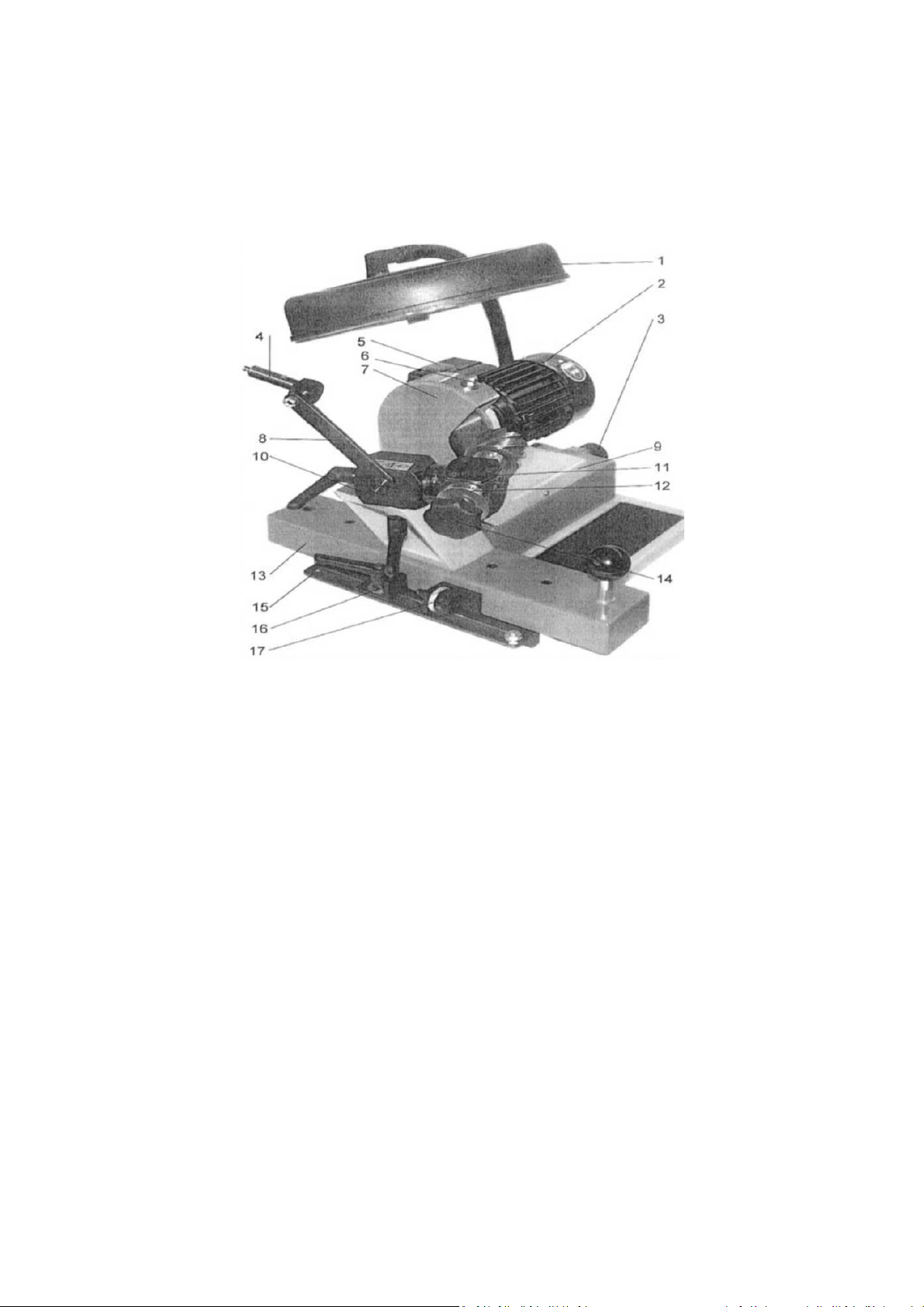
5.1. Description of the operating elements
1. Precision optics (optional) 10. Grinding head support
2. Motor 11. Core drill holder
3. Motor feed 12. Section disk
4. Laser source 13. Guidance carriage
5. Switch 14. Philips-head screw
6. Grinding disk protection fastening 15. Stop rail
7. Grinding disk protection 16. Quick adjusting angle
8. Laser guidance rod 17. Fine tuner
9. Motor angle
5.2 Adj sting and installing the machine
5.2.1 Replacing the index plate
The index plate of the core drill grinding machine determines the precision of the grinding of
core drills with various numbers of teeth.
As standard the machine is supplied including index plate 8/10 for use with cutters with 4, 5,
8 and 10 teeth. See chapter 7. Accessories for optionally available index plates.

8
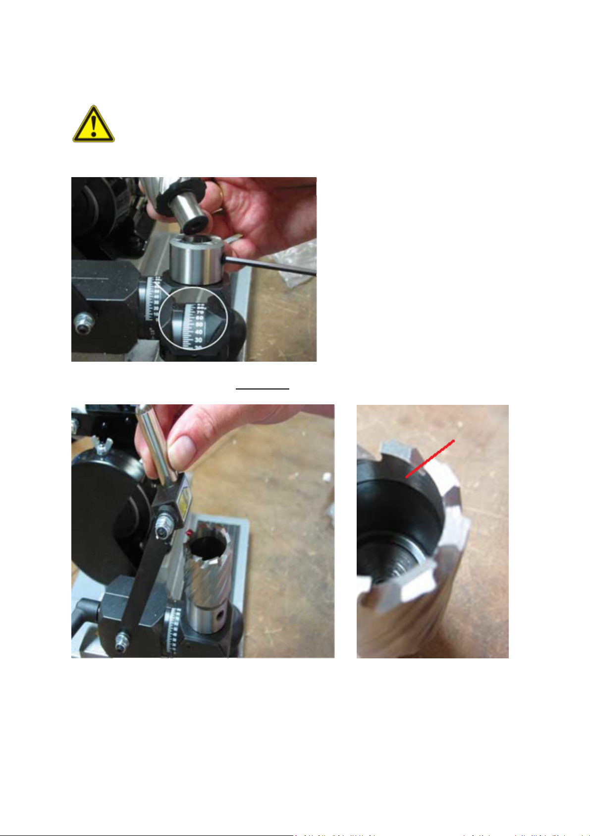
Replacing the index plate
Select the appropriate index plate for your core drill. To replace the index plate turn the
knob in the clockwise direction until the grub screw in the index plate is facing upwards.
Tighten the edge screw (refer to Figure a). Turn the knob in anti-clockwise direction. Loosen
the grub screw (Allen key 2.5) and remove the index plate.
Inserting the index plate
Place the selected index plate on the shaft. Make sure one of the grooves on the side you
want to use is placed against the spring-loaded selector.
Tighten the grub screw lightly and turn the knob in the clockwise direction and tighten it.
Then fully tighten the grub screw on the index plate.
9
5.2.2 Aligning a core drill
While performing the adjustments, please note that the drill cutters are very
sharp and you can suffer physical injuries easily. Always wear safety gloves.
1) Set the core drill holder at 90 degrees.
2) Switch on the laser beam with the red button on top of the laser beam housing
3) Direct the laser beam with the help of the laser guidance rod to align it above one of
the teeth.
4) Rotate the core drill in the holder until the laser beam only just touches the tip of the
selected tooth.
5) MARK THE F RST AL GNED TOOTH
10
SPECIAL NOTE:
While adjusting the core drill in the holder, please ensure that the grub screw is not in
contact with a flat position of the Weldon shank of the cutter. To prevent the slightest of
unintended movement of the cutter the grub screw must lie on the rounding of the cutter
shank.
5.3 Operating the machine
Use eye protection
Always wear protective glasses while working with the Euroboor core drill grinding machine
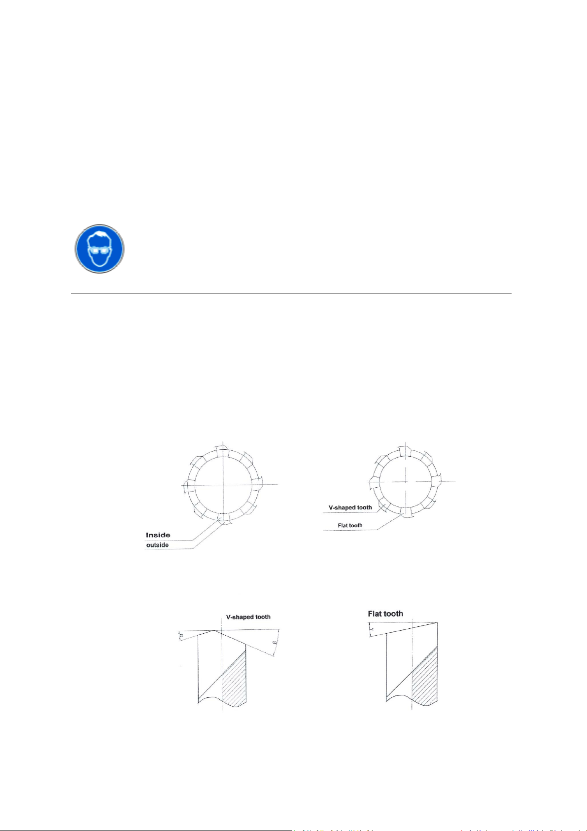
Core drills come in different variations. The variations with matching grinding order are:
1) Only V-shaped teeth
a. nner surface
b. Outer surface
2) Alternating flat & V-shaped teeth
a. nner surface V-shaped teeth
b. Outer surface V-shaped teeth
c. Flat teeth
11
5.3.1 Grinding the core drill teeth
Different manufacturers produce different variations of core drills with different diameters.
f you have the manufacturer provided grinding instructions of your core drill, use the data
specified in the document. f you do not have grinding instructions provided by the
manufacturer of your core drill, we recommend the following general base settings:
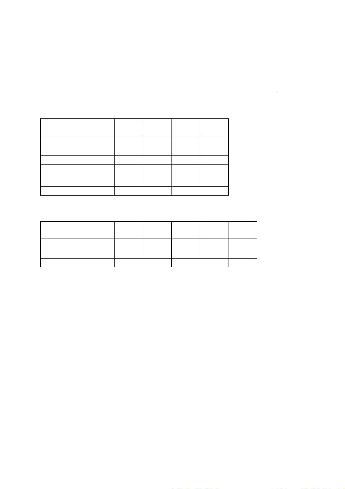
STANDARD CORE DRILLS
Shape of teeth Column
Scale
Column
Scale
Cutter
Holder
Cutter
Holder
V-Shaped teeth nside Outside nside Outside
All dividing disks 20° 7.5° 5° 22°
Flat teeth Column
Scale
Arbor
Holder
All dividing disks 6° 15°
TCT CORE DRILLS
Shape of teeth Cutter
Holder
Column
Scale
Column
Scale
Cutter
Holder
Cutter
Holder
Teeth Outside nside Outside nside Outside
All dividing disks 22° 20° 7.5° 7.5° 17.5°
FOLLOWING INSTRUCTIONS ARE SPECIFIED AS BASE GUIDELINE FOR STANDARD
EUROBOOR HSS ANNULAR CUTTERS. ALWAYS CHECK MEASUREMENTS AND ANGLES AND
FINE-TUNE WHEN NECESSARY.
FOR ALTERNATIVE CUTTERS, USE MANUFACTURER PROVIDED SPECIFICATIONS OR REVERT
TO THE SETTINGS PROVIDED ON THIS PAGE.

12
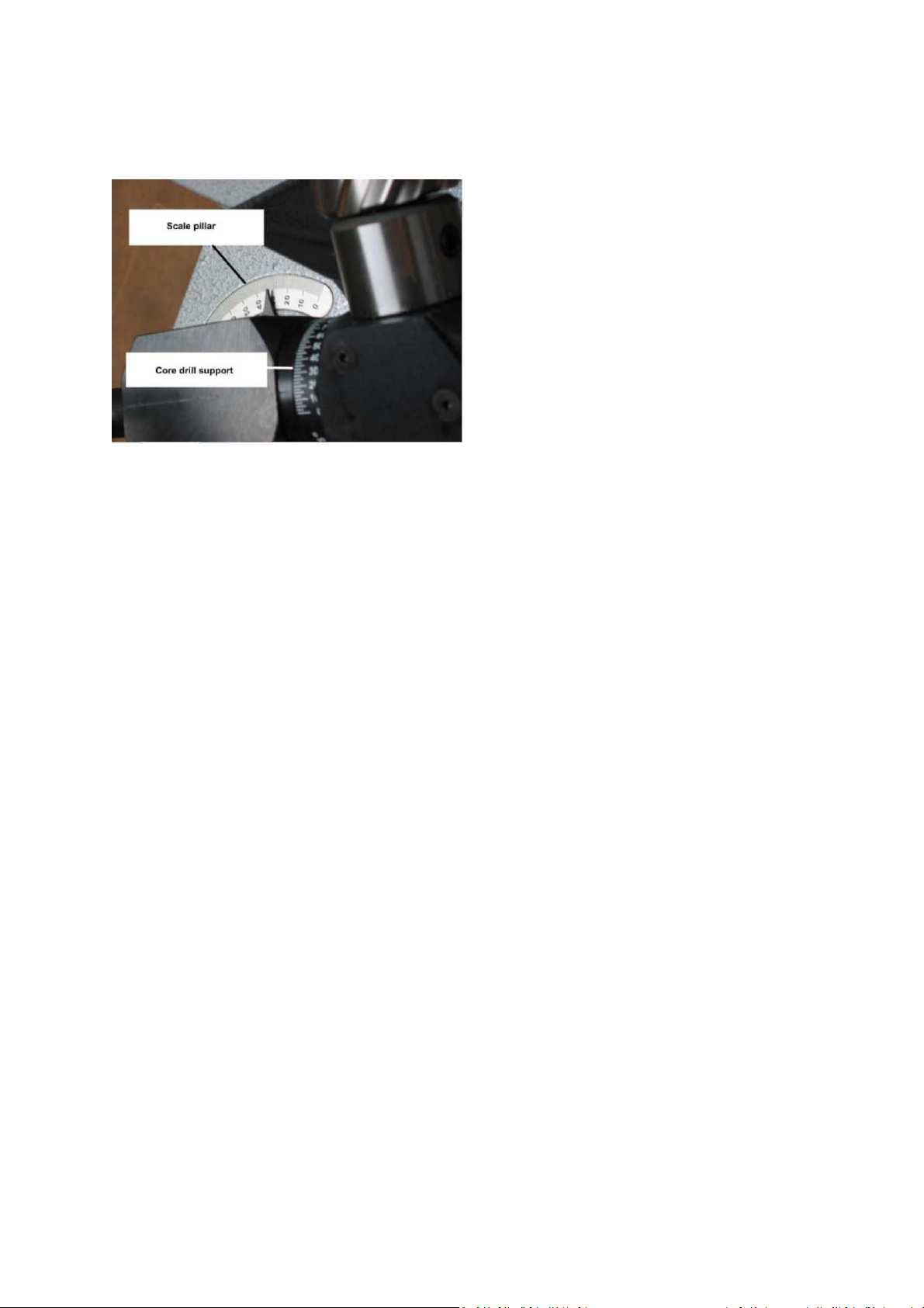
Grinding inner s rface
Mark the inner surface of the first tooth
Set the column scale to 27.5°
Set the cutter holder to 7.5°
1) After making these angular settings, move both the cutter holder slide towards the
grinding wheel, and grinding wheel towards the cutter.
SPECIAL NOTE
Grind the marked tooth as last. To start, first grind the next tooth.
2) Slide the core drill onto the stationary grinding disk and set its lateral stop on it (see
figure below). Fine-tune the setting by turning the adjusting screw of the stop in the
reverse direction till the next milling tooth is no longer in contact with the grinding
disk.
3) Now grind the outer free surface set by you by moving the guidance carriage to and
fro. The delivery from the motor feed should be low and it should remain constant
for all other cuts. This way you can ensure that the cuts remain at the same level.
4) After grinding the first cut, pull the guide carriage back and turn the star-shaped
screw head in the clockwise direction (direction of the arrow) till the next section is
reached. To position the next cut, do not change the motor feed. Repeat the grinding
operation till all the cuts have been ground.

13
Grinding o ter s rface
With the inside of the marked V-shaped tooth now ground, mark the outer surface of the
same tooth
Set the column scale to 17.5°
Set the cutter holder to 31°
Repeat steps 1 – 4 described under “Grinding inner surface”
5.3.2 Grinding stretched s rfaces
The use of Euroboor optional grinding disk ERM3.0011 (see also chapter 7. Accessories) is
recommended for grinding the stretched surfaces on standard Euroboor cutters.
For information on replacing the diamond disk, please refer to chapter 5.4 Replacing the
Grinding Disk.
14
Set the column scale to 50°
Set the cutter holder to 25°
SPECIAL NOTE
The value of this setting is not the same for all core drills.
1) Move the core drill along the grinding disk in stationary condition, and if necessary,
correct the angular setting (the angular setting can be in the 15 to 30 degree range).
2) After making the angular adjustments, bring the core drill with the guide carriage
and motor feed near the grinding disk. Grind the stretched surface with the radial
diamond disk provided for the purpose. Do not grind the tooth that was aligned
(marked tooth). nstead, grind the next stretched surface below it.
3) Move the core drill along the grinding disk in stationary condition until the stretched
surface touches the diamond disk. Set the lateral stop and the fine tuner in such a
way that the stretched surface can be ground.
4) Now grind the stretched surface set by you. Feed through the fine tuner should be
low, and it should be uniform for all the stretched surfaces. After grinding the first
stretched surface, pull the guidance carriage back and turn the knob in the clockwise
direction (direction of arrow) right up to the next section. You can position the next
stretched surface in this manner. Do not alter the motor feed and the fine tuner
position. Repeat the grinding process till all the stretched surfaces have been
ground.

15
5.4 Replacing the grinding disk
Always pull the plug out of the mains socket before replacing the grinding disk. No
core drill should be in the holder while replacing the grinding disk.
1) Unscrew the wing nut at the top
2) Remove the grinding disk cover
3) Loosen the nut bolt retaining the grinding disk with an Allen key and pull off the
grinding disk out of the motor shaft.
4) Assemble the appropriate grinding disk on the motor shaft. Make sure the grinding
wheel can rotate freely without touching any of the machine parts.
5) Fasten the retaining bolt
6) Reassemble the grinding disk cover on the machine

16
6. Maintenance
6.1 Cleaning and l brication
-The grinding dust in the core drill grinding machine must be cleaned at least once a
week with a soft brush
-Remove stubborn impurities with a usual commercial machine cleaner
-After cleaning, all moveable parts of the machine must be lubricated with a few
drops of machine oil
-To avoid corrosion of the blank parts, some oil should also be applied on these parts
and then a soft cloth should be used to wipe the oil off
-The motor carriages should be lubricated at least once in six months through the
lubricating nipples at the sides:
6.2 Repairs
For service and repair on assemblies like the grinding head or the guide carriage seek the
help of a specialized Euroboor repair point, to make sure the values and settings are
maintained or corrected.

17
7. Accessories
ERM3.0001 CBN Grinding wheel
ERM3.0002 SDC Grinding wheel
ERM3.0003 Cutter holder 31,75 mm (1 ¼”) Weldon
ERM3.0004 Lock wrench M8x15
ERM3.0005 Head support wrench M8x30
ERM3.0006 Laser beam generator
ERM3.0007 Head support wrench M8x75
ERM3.0008 ndex plate 6/7
ERM3.0009 ndex plate 8/10
ERM3.0010 ndex plate 9
ERM3.0011 CBN Grinding wheel (stretched surfaces)

18
8. Warranty
Euroboor warranty on ERM.100/3 covers material defects and manufacturing mistakes.
Wear and tear parts conditioned by operation, lack of maintenance, improper use of the
machine and damages caused by the use of force are excluded from warranty.
For additional details contact your point of sales.
Always provide the serial n mber of the machine when s bmitting for g arantee.
The machine can be returned only after obtaining prior approval from our side. We reserve
the right to charge transportation costs in case of unauthorized returns.
Other manuals for ERM.100/3
2
Other Euroboor Grinder manuals

Euroboor
Euroboor ADG.2S User manual

Euroboor
Euroboor ADG.2A User manual

Euroboor
Euroboor ADG.2A User manual

Euroboor
Euroboor AGR.1200 User manual

Euroboor
Euroboor EDG.600 User manual

Euroboor
Euroboor ADG.2E User manual

Euroboor
Euroboor AGR.840 User manual

Euroboor
Euroboor AGR.1400 User manual

Euroboor
Euroboor AGR.2200/180 User manual

Euroboor
Euroboor EDG.600 User manual


