2© 2020 DJI All Rights Reserved.
Disclaimer
Thank you for purchasing the ROBOMASTERTM Development Board Type C (hereinafter referred to
as “Board Type C”). Read this disclaimer carefully before using this product. By using this product,
you hereby agree to this disclaimer and signify that you have read it carefully. Install and use this
product in strict accordance with all related documents. Users bear the responsibilities in all the
consequences caused by using this product. DJITM will not bear any legal responsibilities for any
damages due to improper use, installation, or modication.
DJI and ROBOMASTER are trademarks of DJI and its affiliated companies. Names of products,
brands, etc., appearing in this document are trademarks or registered trademarks of their respective
owner companies. This product and document are copyrighted by DJI with all rights reserved. No
part of this product or document shall be reproduced in any form without the prior written consent or
authorization of DJI. The nal interpretation right of this disclaimer is reserved by DJI.
This document and all other collateral documents are subject to change at the sole discretion of DJI.
For up to date product information, visit http://www.robomaster.com and click on the product page for
this product.
Warning
1. Connect the cables correctly by following the instructions in this document. Otherwise, the cables
or the Board Type C may be seriously damaged.
2. Make sure there are no short-circuits and all the cables are in good condition. DO NOT use cables
that have been damaged in any way.
3. Make sure to use the product in strict accordance with the specications listed in this document,
including those related to voltage and temperature. Failure to do so may reduce the product
service life or even lead to permanent damage.
4. To avoid physical damage, make sure to assemble the Board Type C correctly.
5. If you detect any ames, smoke, strange smells, or other abnormalities, disconnect the Board Type
C from the power source immediately.
6. DO NOT open the silicone case. Otherwise, foreign objects may fall inside and the performance of
the Development Board Type C may be negatively affected.
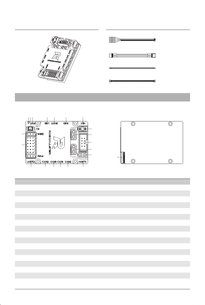
RoboMaster Development Board Type C
Introduction
Designed to work with the products of RoboMaster and other accessories, the compact Development
Board Type C uses a high-performance STM32 microcontroller chip and supports a wide range of
voltage inputs. The highly integrable Board Type C boasts an expansion interface, communication
interface, and high precision IMU sensors and features an anti-reverse connection and anti-
overvoltage protection. The Board Type C provides rich routines and can be widely used in elds
such as robotics competitions, research and education, and automation equipment.