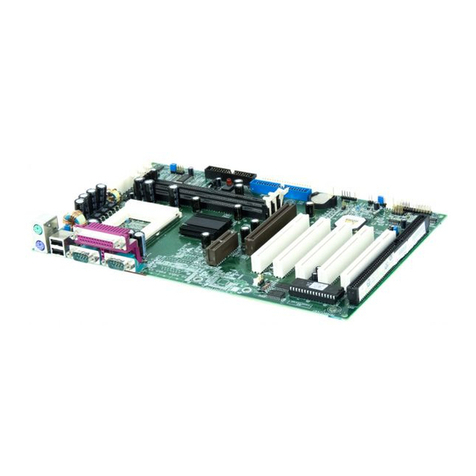
QDI KinetiZ 7A User manual

Declaration ofconformity
QUANTUMDESIGNS(HK)LTD.
5/FSomersetHouse,TaiKoo Place 979 KingsRoad,
QuarryBay,Hong Kong
declaresthatthe product
Mainboard
KinetiZ7A
isin conformity with
(reference to thespecification underwhich conformity isdeclared in
accordance with 89/336 EEC-EMCDirective)
þEN55022 Limitsandmethodsofmeasurementsofradiodisturbance
characteristics ofinformationtechnologyequipment
þEN50081-1GenericemissionstandardPart1:
Residential,commercialandlightindustry
þEN50082-1GenericimmunitystandardPart1:
Residential,commercialandlightindustry
EuropeanRepresentative:
QDICOMPUTER(UK)LTDQDICOMPUTER(SCANDINAVIA)A/S
QDISYSTEMHANDELGMBHQDICOMPUTER(NETHERLANDS)B.V.
QDICOMPUTER(FRANCE)SARLQDICOMPUTERHANDELSGMBH
QDICOMPUTER(ESPANA)S.A.QDICOMPUTER(SWEDEN)AB
Signature:Place/Date:HONGKONG/2000
Printed Name:AndersCheung Position/Title:President

Declaration ofconformity
TradeName:QDIComputer(U. S. A. )Inc.
ModelName:KinetiZ7A
ResponsibleParty:QDIComputer(U. S. A.)Inc.
Address:41456 Christy Street
Fremont, CA94538
Telephone:(510)668-4933
Facsimile:(510)668-4966
EquipmentClassification:FCC Class BSubassembly
TypeofProduct: Mainboard
Manufacturer:QuantumDesigns(HK)Inc.
Address:5/F, SomersetHouse, TaiKoo Place
979 KingsRoad, Quarry Bay, HONG
KONG
SupplementaryInformation:
ThisdevicecomplieswithPart15 oftheFCCRules.Operation issubjectto
thefollowingtwoconditions:(1)thisdevicemaynotcauseharmfulinterfer-
ence,and(2)thisdevicemustacceptany interferencereceived,including
interference thatmaycauseundesiredoperation.
Signature:Date:2000

CONTENTS
Facilitéde vitesseInitialisation(Francais)................................................ 1
1.Introduction .............................................................3
Overview................................................................................................ 3
KeyFeatures.......................................................................................... 3
Introduction toNewFeatures................................................................. 5
2.Installation Instructions............................................7
ExternalConnectors.........................................................................7
PS/2Keyboard&PS/2MouseConnector............................................... 7
USB1&USB2.......................................................................................... 7
USB3&USB4.......................................................................................... 7
ParallelPortConnectorand SerialPortConnector.................................. 8
Line-injack,Microphone-injack,Speaker-outjack and
MIDI/Joystickconnector.......................................................................... 8
ATXPowerSupplyConnector&PowerSwitch(POWERSW)............... 8
HardDiskLEDConnector(HDLED)........................................................ 9
ResetSwitch(RESET)............................................................................ 9
SpeakerConnector(SPEAKER).............................................................. 9
PowerLEDConnector(PWR_LED).......................................................... 9
ACPILEDConnector(ACPI_LED)............................................................ 9
GREENLEDConnector(GREEN_LED).................................................... 9
HardwareGreen Connector(SLEEP)..................................................... 9
Fan Connector(CPUFAN&CHSFAN).................................................. 10
Wake-UpOnLAN(WOL)...................................................................... 10
Wake-UpOnInternalModem(WOM).....................................................11
InternalAudioConnectors(AUX,CDLIN,MODEM)..................................11
Audio/ModemRiserInterfaceConnector(AMR).................................... 12
ChassisSecuritySwitch(CHSSEC)..................................................... 12
InfraredHeader(IrDA).......................................................................... 12
ExpansionSlots&I/OPortsdescription................................................ 13
JumperSettings............................................................................... 13
Suspend toRAMSwitch(J13)............................................................. 13

CONTENTS
BIOS-ProtectEasyJumper(JAV)...............................................................14
ClearCMOS(JCC)......................................................................................14
OverclockingJumperSetting(JFSB)........................................................15
Enable/Disableonboardaudio(JSD)..........................................................15
3.BIOSDescription ......................................................................... 17
UtilitySupport........................................................................................17
AWDFLASH.EXE.......................................................................................17
AWARD BIOSDescription ..................................................................18
EnteringSetup...........................................................................................18
Load Fail-SafeDefaults............................................................................18
LoadOptimized Defaults...........................................................................18
StandardCMOSFeaturesSetup............................................................. 18
AdvanceBIOSFeaturesSetup............................................................... 22
AdvanceChipsetFeaturesSetup........................................................... 24
IntegratedPeripherals............................................................................. 26
PowerManagementSetup...................................................................... 28
PnP/PCIConfigurationsSetup ................................................................. 30
PCHealthStatus..................................................................................... 31
Frequency/VoltageControl.......................................................................32
SetSupervisor/UserPassword................................................................33
BootwithBIOSdefaults.......................................................................... 33
AppendixAQDIDriverCD 2000 ................................................. 35
AppendixBBootLogo ................................................. 37
RecoveryEasy ...............................................................39
Introduction ...............................................................................................39
OperationProcess ....................................................................................39
FAQ...........................................................................................................44

ManualforKinetiZ7A
KinetiZ7A
Installation delacartemèreKinetiZ7A
1.Assurez-vousque votreensembleestcomplet: cartemère,câblesIDEetFLOPPY,
noticed’utilisationetCD-ROMd’installation.
2.Vérifiezque l’alimentation estdébranchéeetreliez-vousàlaterreparune courroieà
votrepoignet. Adéfaut, maintenezlecontactde vosdeuxmainsavecun objetlui-
mêmereliéàlaterre,ou une partieenmétalde votresystème.
3.Fixezlacartemèredansleboîtiergrâceauxvisfourniesaveccelui-ci.
4. Insérezleprocesseurdansson logementavecson ventilateurque vousbrancherez
auconnecteur«CPUFAN».
5. Insérezla/lesbarrette(s)mémoiredanslesslotsDIMM.
6. InstallezvoséventuellescartesPCIetAMRdanslesslotsprévusàceteffet(voirpage
centraledu manuel).
7.BranchezvospériphériquesIDEetFLOPPY surlesconnecteursprévusàceteffet
grâceauxnappesfourniesaveclacarte.Vérifiezque lesensde branchementest
correct(liserérouge du câblesurlabroche 1du connecteur).
8.Reliezlescâblesdu boîtierauxconnecteursprévusàceteffet(Connecteur
d’alimentation,LEDde marche/arrêt, disquedur,haut-parleur…).Refermezleboîtier.
9.Branchezlespériphériquesexternessurlessortiesdu fondde panier:clavier,souris
PS/2,périphériquesUSB,moniteur,imprimante…
10.Lorsquetouslesélémentsdusystèmesontinstallés physiquement, rebranchezl’unité
centrale.

ManualforKinetiZ7A
Installation du KinetiZ7Asystème
1.Chipset:
LespilotesdeschipsetsVIAdu répertoire\ChipDrv\Viapeuventêtreutiliséssurcettecarte
mère.
InsérezleCD-ROMdansvotrelecteuretcliquezsur« ChipsetDriver »pourinstallerlespilotes
2.LogicielPC-cillin98:
PourWindows95/98,version anglaise,danslerépertoire\Pccillin\Win9X.Lancez
setup.exepourl’installation.
PourWindowsNTversion anglaise,il setrouvedanslerépertoire\Pccillin\Winnt40,
lancezsetup.exe.
Numérode série:PNEF-9991-6558-5857-5535.
3.QDIManageEasy:
Lancezlesetup.exedu répertoire\QMEpourinstallerleManageEasy.Pourdesinfor-
mationsdétailléessurleManageEasy,référez-vousaumanuelManageEasydurépertoire
\Doc.
N’oubliezpasde redémarrervotresystèmepourqueleschangementssoientprisen
compte.
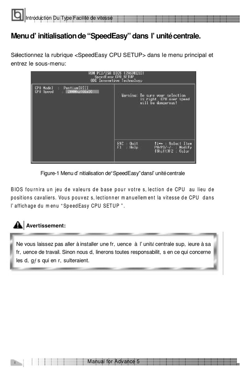
4.RecoveryEasy
RecoveryEasy™,ladernièreinnovationde QDI, permetde protégerlesystèmedesdestruc-
tionsencréantune «partitionmiroir»de lapartition courantedudisqueduretensauvegardant
touteslesdonnéesdansce«miroir».
Cetteutilitairefournitpartitiondu disque,récupération/sauvegarde desdonnées,récupération/
sauvegardedesréglagesdu CMOSetfonctionsmulti-boot.
RecoveryEasypermetégalementlaprotectiondusystèmecontrelesdiverstypesdevirusde
boottelsque CIH.Danslecasoùlesystèmeestperdusoitparerreur,soitàcaused’unvirus,
il peutêtrerécupérédepuislapartition miroir.Cetteinnovation utiliselatechnologiedu Bios
intégréquin’occupenil’espacedisque,nilamémoiredusystème.C’estlasolution idéalepour
l’utilisateur.
IlfautpresserlestouchesCtrl+BkspetF12 pourentrerdanslesinterfaces«Recovery» et
«Partition»durantledémarragedu Bios.
ATTENTION :lisezattentivementlemanuelduRecoveryEasytraduitsurleCD-ROMQDI
avantd’installercettefonction.
Trèsimportant :n’oubliezpas votremotdepasse,fautedequoivousn’auriez
plusaccèsauRecoveryEasy,mêmeaprèsavoireffectuéun ClearCMOS.

ManualforKinetiZ7A
Chapter1
Introduction
Chapter1
Chapter1
Introduction
Overview
The KinetiZ7Agreen mainboardutilizesthe VIAApolloKX-133 chipset, providing acost-
effectivePC/ATXplatformwithperfectcapabilityand highperformancetosupportAMDSlot
AAthlon processors.The VIA®VT8371 chipsetand VIA®VT82C686Achipsetprovide
somenewfeaturessuchasAGP4Xmode and UltraDMA66.Equipped withthree memory
modulesockets,PC133MHzSDRAMand768MBPC133ECCornon-ECCSDRAMDIMMscan
be supported.It alsoprovidesadvanced featuressuchaswake-up on LANand wake-up
on internal/externalmodemfunction.Suspend toRAM,the optimalimplementation ofthe
Advanced Configuration andPowerInterface(ACPI)specification,makesthe PC’s power
consumption droptothe lowestpossibleleveland enablequickwakeup.ManageEasy,our
systemmanagementapplication isalsosupplied toenableremotemonitoringand configura-
tion ofthe system.
Key Features
Formfactor
l ATXformfactorof305mm x210mm.
Microprocessor
lSupportsAMDSlotAAthlon processorsat500/550/600/650/700/750/800/850MHz
and futureprocessors.
lSupports200MHzhostbus.
lOn-boardVDDQ(forAGP),VSRAM(forLICache),2.5Vregulatorsand 3.3V
switching powersupply.
lMutiphasepowerfrom1.30 -2.05VforAthlon Processors.
Chipset
l ApolloKX-133 chipset: VT8371,VT82C686A.
Systemmemory
lProvidesthree168pinDIMMsockets,supports768MBPC100/133ECC ornon-ECC
SDRAMDIMMS,VCMandSDRAM.
lMinimummemorysizeis8MB,maximummemorysizeis1.5GMB.
lSDRAM64bitdatainterfacewithECC support.
On-boardIDE
lSupportstwoPCIPIOandBusMasterIDEports.
l
TwofastIDEinterfacessupporting fourIDEdevicesincluding IDEharddisks and
CD-ROMdrives.
l
Supports“UltraDMA/33”SynchronousDMAmodetransferringupto33Mbytes/sec.
l
Supports“UltraDMA/66”SynchronousDMAmodetransferringupto66Mbytes/sec.
l
Integrated 16x32bitbufferforIDEPCIBurstTransfers.

ManualforKinetiZ7A
Introduction
On-chipI/O
l
One floppyportsupporting up totwo3.5″or5.25″floppydriveswith
360K/720K/1.2M/1.44M/2.88Mformat.
l
Twohighspeed16550fastcompatibleUARTs(COM1/COM2/COM3/COM4
selective)with16-bytesend/receiveFIFOs.
l
One enabledparallelportatthe I/Oaddress 378H/278H/3BCHwithadditional
bi-directionI/Ocapabilityandmulti-mode asSPP/EPP/ECP(IEEE 1284compliant).
l
Circuitprotection provided,preventing damage tothe parallelportwhen a
connected printerispowered up oroperated atahigh voltage.
l
SupportsLS-120 floppydisk driveand Zipdrive.
l
All I/Oportscan be enabled/disabled inthe BIOSsetup.
On-chipAudio
l
BuildinVIA®82C686A
l
16-bitStereo Codec
AGPSLOT
l
Supports4Xmode &AGP2.0compliant.
Advancedfeatures
l
PCI2.2Specificationcompliant.
l
ProvidesTrend ChipAwayVirus® OnGuardand PC-Cillinsoftwarewithkilling virus
function.
l
ProvidesfourUSBports,on-boardPS/2mouseand PS/2keyboardports.
l
Providesinfrared interface.
l
SupportPC99 color-coding connectorSpecification.
l
SupportsWindows98/Windwos2000 softwarepower-down.
l
Supportswake-up on LANand wake-up on internal/externalmodem.
l
Supportsautofan off when the systementerssuspend mode.
l
Provideson-board3.3VregulatortosupportATXpowersupplywithout3.3Voutput.
l
supportssystemmonitoring(monitorssystemtemperature,CPUtemperature,voltages,
chassisintrusion and fan speed).
l
Providesmanagementapplication suchasManageEasy.
l
ProtectsthesystemBIOSfrombeing attacked byseverevirussuchasCIH,by
enabling“BIOS-ProtectEasy” inCMOSsetup orclosingthe Jumper“JAV”.
BIOS
l
Licensed advanced AWARDBIOS,supportsflashROMwith2Mbitmemorysize,
plug and playready.
l
SupportsIDECD-ROMorSCSIbootup.
Greenfunction
l
SupportsACPI(AdvancedConfiguration and PowerInterface)and ODPM(OS
DirectedPowerManagement).
lSupportsthreegreen modes:Doze,Standbyand Suspend.
lSupportsACPIpowerstatus:S0,S1,S3(STR),S5(Soft-off).
Expansion slots
l1ISAslot, 5PCIslots,1AGPand1AMR.

ManualforKinetiZ7A
Chapter1
IntroductiontoNewFeatures
BIOS-ProtectEasy
The BIOSofthemainboardiscontained inside the FlashROM.SeverevirusessuchasCIH
virusaresodangerousthatitmayoverwritethe BIOSofthe mainboard.If the BIOShas
been damaged,the systemwill be unabletoboot. Weprovide the following solution which
protectsthe systemBIOSfrombeing attackedbysuchviruses.
Therearetwochoiceswhichcan implementthisfunction.
1.Setthe jumper(JAV)asclosed,the BIOScan notbe overwritten.
2.Setthe jumper(JAV)asopen,meanwhileset“BIOS-ProtectEasy”asEnabledinAWARD
BIOSCMOSSetup.Inthisway,the BIOScannotbe overwritten,buttheDMIinformation
can be updated.
Refertopage 14 fordetailed information on jumpersetting,and page 22 forrelated BIOS
setting.
UltraATA/66
According tothe previousATA/IDEharddrivedatatransferprotocol,the signaling wayto
send datawasinsynchronousstrobe mode byusing the rising edge ofthe strobe signal.
The UltraATA/33 protocoldoublesthe bursttransferratefrom16.6MB/sto33.3MB/s,by
using boththe rising and falling edgesofthe strobe signal,thistimeUltraATA/66 doubles
the UltraATAbursttransferrateonceagain(from33.3MB/sto66.6MB/s)byreducing setup
timesandincreasing the stroberate.Thefasterstrobe rateincreasesEMI, whichcannotbe
eliminated bythe standard40-pincableused byATAand UltraATA.Toeliminatethis
increaseinEMI, anew40-pin,80-conductorcableisneeded.Thiscableadds40 additional
ground linesbetween eachoftheoriginal40 ground andsignallines.The additional40 lines
helpshieldthe signalfromEMI,reducecrosstalkand improvessignalintegrity.
UltraATA/33 introduced CRC (CyclicalRedundancy Check),anewfeatureofIDEthat
providesdataintegrityandreliability.UltraATA/66usesthe sameprocess.TheCRC value
iscalculated byboththe hostand the harddrive.Afterthehost-requestdataissent, the
hostsendsitsCRCtothe harddrive,andtheharddrivecomparesittoitsownCRC value.
If the harddrivereportserrorstothe host, then the hostretriesthe command containing
theCRCerror.
UltraATA/66 technologyincreasesbothperformanceand dateintegrity.Howeverthere
arebasicallyfiverequirementsforyoursystemtorun inUltraATA/66 mode:
1.The systemboardmusthaveaspecialUltraATA/66detectcircuit, suchas
KinetiZ7Amainboard.
2.The systemBIOSmustalsosupportUltraATA/66.
3.The operating systemmustbe capableofDMAtransfers.Win95 (OSR2),
Win98 and WindowsNTarecapable.
4.AnUltraATA/66 capable,40-pin,80-conductorcableisrequired.
5.UltraATA/66compatibleIDEdevicesuchasaharddriveorCD-ROMdrive.
ManualforKinetiZ7A
PC-133Memory
PC133 SDRAMUnbuffered DIMM definesthe electricaland mechanicalrequirementsfor
168-pin,3.3Volt,133MHz,64/72-bitwide,Unbuffered SynchronousDRAMDualIn-Line
MemoryModules(SDRAMDIMMs).Relatively,the peakbandwidthofPC-133memoryis
the 33%higherthan PC-100memory.TheselatestSDRAMsarenecessarytomeetthe
enhanced133MHzbusspeed requirement.
Suspend toRAM
Suspend toRAMisacost-effective,optimalimplementation ofthe Advanced Configura-
tion and PowerInterface(ACPI)1.0specification,whichmakesaPC’s powerconsump-
tion drop tothe lowestpossibleleveland enablesquick wakeup.When the systemisin
Suspend-to-RAMstatus,the systemcontextismaintainedinsystemmemory,the system
consumesonlyasmall fraction ofthe powerused forfull operation.Instead ofshutting
downthe systemtosavepowerwhen notinuseand then having torebootlater,Sus-
pend-to-RAMsolution enablesthe systemtoquicklywakeup,restoring all applications
and features,enabling operation inafewseconds.
Toimplementthisfunction,the following requirmentsareessential:
1.Powersupplyrequirements:The currentof5VSB line ofthe powersupplyshouldbe
morethan 0.75A.
2.Setthe JumperJ13 withpin1&pin2 closed.Refertopage 13 fordetailed information.
3.TheBIOSoption“ACPIfunction”shouldbeenabled,and“ACPISuspendType”should
be setasS3inAWARD BIOSCMOSsetup.Refertopage28 fordetailed information.
4.AnACPI-enabled operatingsystemsuchasWindows98 orWindows2000 familyis
needed.NavigatetotheCD-ROMdrivefromtheMS-DOSCommandPromptandenter
the following fromthe Win98 directoryon the CD:
D:\SETUP/PJ
(ThismanualassumesthatyourCD-ROMdevicedriverletterisD:)
Windows98 will be installed withACPIenabled.
ForWindows98 SE and Windows2000,justinstall themdirectly.
5.Three ways toenterSuspend-to-RAMstatusunderACPI-enabled Windows98:
lClick Start->Shutdown->Standbytoenablethe systemtoenterSuspend-to-
RAMstatus.
lClick Start->Setup ->ControlPanel->PowerManagement->Advanced and
chooseStandbyitem,the systemwill enterSuspend-to-RAMstatuswhen you
press powerbutton.
lFromPowerManagementPropertiesinControlPanel,setthe latency timein
SystemStandby,the systemwill enterSuspend-to-RAMstatuswhen timeout.
The sameways used topowerup the systemcan be used towakeup the systemfrom
Suspend-to-RAMstatus.Forexample,pushingthe powerbutton,through the Wake-on-
LAN,Wake-on-Modemfunction orRTCAlarm.
Introduction

ManualforKinetiZ7A
Chapter2
Installation Instructions
Chapter2
Installation Instructions
Thissection coversExternalConnectorsand JumperSettings.Refertothe mainboard
layoutchartforlocationsofall jumpers,externalconnectors,slotsandI/Oports.Further-
more,thissection listsall necessaryconnectorpinassignmentsforyourreference.The
particularstateofthejumpers,connectorsandportsareillustratedinthe following figures.
Beforesetting thejumpersorinserting theseconnectors,pleasepayattentiontothe direc-
tions.
Besuretounplug theAC powersupplybeforeaddingorremoving expansion
cardsorothersystemperipherals,otherwise yourmainboardand expansion
cardsmightbeseriouslydamaged.
ExternalConnectors
PS/2KeyboardConnector,PS/2Mouse Connector
PS/2keyboardconnectorisforthe usage ofPS/2keyboard.If using astandardATsize
keyboard,an adaptershouldbe used tofitthisconnector.PS/2mouseconnectorisforthe
usage ofPS/2mouse.
USB1,USB2
TwoUSB portsareavailableforconnecting USB devices.
USB3,USB4
TwoUSB portsarenotavailableon the back panel.Therefore,weprovide a10-pinribbon
cablewithbrackettoconnectBuilt-inon-boardUSB header.(manufacturing option)
chapter2

ManualforKinetiZ7A
ParallelPortConnectorand SerialPortConnector(UART1,UART2)
The parallelportconnectorcan be connected toaparalleldevicesuchasaprinter,while
the serialportconnectorcan be connected toaserialportdevicesuchasaserialport
mouse.You can enable/disablethemand choosethe IRQorI/Oaddress in“Integrated
Peripherals”fromAWARD BIOSSETUP.
Line-injack,Microphone-injack,Speaker-outjack and
MIDI/Joystick connector
The Line-injack can be connected todevicessuchasacassetteorminidisc playerfor
playbackorrecording.TheMicrophone-injack canbe connected toamicrophoneforvoice
input. The Speaker-outjack allowsyou toconnectspeakersorheadphonesforaudio
outputfromthe internalamplifier.
The MIDI/Joystickconnectorallowsyou toconnectagamejoystickoraMIDIdevice.
ATXPowerSupplyConnector&PowerSwitch(POWERSW)
Besuretoconnectthe powersupplyplug tothisconnectorinitsproperorientation.The
powerswitch(POWERSW)shouldbe connected toamomentaryswitch(powerbutton).
When powering up yoursystem,firstturnon the mechanicalswitchofthe powersupply(if
one isprovided),then pushoncethe powerbutton.When powering off the system,you
needn’tturnoff the mechanicalswitch,justPushonce*the powerbutton.
Note:*Ifyou change“soft-off byPWR-BTTN”fromdefault“Instant-off”to“Delay
4Secs”inthe“POWERMANAGEMENTSETUP”section oftheBIOS,thepower
button shouldbepressedformorethan4secondsbeforethesystempowers
down.
Installation Instruction
ATXPowerSupplyConnector
1
20
MIDI/Joystick
SpeakeroutLine inMicrophone in

ManualforKinetiZ7A
chapter2
HardDisk LEDConnector(HD LED)
The connectorconnectstothe case’sIDEindicatorLEDindicatingtheactivitystatusofIDE
harddisk.The connectorhasan orientation.Ifone waydoesn’twork,trythe otherway.
ResetSwitch(RESET)
The connectorconnectstothe case’s resetswitch.Press theswitchonce,the system
resets.
SpeakerConnector(SPEAKER)
The connectorcanbe connected tothe speakeron the case.
PowerLEDConnector(PWRLED)
The powerLEDhasfourstatus.When the systemisinpowerup status,the LEDison.
When thesystemisinsuspend status,theLEDisblink.Whenthe systemisinSuspend to
RAM,theLEDisoff. When thesystemisinSoft-Offstatus,the LEDisoff.Theconnectorhas
an orientation.
ACPILEDConnector(ACPI_LED)(Reserved)
The ACPILEDisdouble-colorlightswiththreepins.Pin1&Pin2 drivedifferentcolorlights.If
Pin1 drivesthe yellowlight,Pin2 drivesthe green light, the following statuswill comeout.
Whenthesystemisinpowerupstatus,theLEDisgreenon.When thesystemisinsuspend
status,the LEDisgreen blink.When the systemisinsuspend toRAMstatus,the LEDis
orange on.When the systemisinsoft-off status,the LEDisoff.
GREENLEDConnector(GREEN_LED)
The GREENLEDhasfourstatus.When the systemisinthreestatus(including powerup,
suspend,soft-off),the LEDisoff. When thesystemisinsuspend toRAMstatus,the LED
ison.
HardwareGreenConnector(SLEEP)
Pushoncethe switchconnected tothisheader,the systementerssuspend mode.

ManualforKinetiZ7A
Installation Instruction
FanConnector(CPUFAN,CHSFAN)
The fanspeed ofthesetwofanscanbe detected andviewedin“PCHealthStatus”section
ofthe BIOS.Theywill be automaticallyturned off afterthe systementerssuspend mode.
Wake-UpOnLAN (WOL)
Through the Wake-UpOnLANfunction,awakeeventoccurring fromthe networkcan
wakeup the system.If thisfunction istobe used,pleasebe surean ATX2.01 power
supplyofwhich5VSB line iscapableofdelivering 720mA,and aLANadapterwhich
supportsthisfunctionareused.Then connectthisheadertothe relevantconnectoron the
LANadapter,set“WakeUpOnLAN/Ring”asEnabledinthe“POWERMANAGEMENTSETUP”
section ofthe BIOS.Save&exit, then bootthe operating systemoncetomakesurethis
function takeseffect.
CPUFAN
CHSFAN

ManualforKinetiZ7A
chapter2
Wake-UpOnInternalModem(WOM)
Through the Wake-UpOnInternalModemfunction,the systemwhichisinthe power-off
statuscanbe powered on byaring signalreceivedfromthe internalmodem.If thisfunction
istobe used,be surean internalmodemcardwhichsupportsthe function isused.Then
connectthisheadertothe relevantconnectoronthe modemcard,set“WakeUpOnLAN/
Ring”asEnabledinthe “POWERMANAGEMENTSETUP”sectionoftheBIOS.Save&exit,
then bootthe operating systemoncetomakesurethisfunction takeseffect.
InternalAudioConnectors(AUX,CDLIN,MODEM)
AUXand CDLINconnectorsallowyou toreceivestereo audioinputfromsuchsound
sourcesasaCD-ROM,TVtuner,orMPEGcard.TheMODEMconnectorallowstheonboard
audiotointerfacewithavoicemodemcardwithasimilarconnector.It alsoallowsthe
sharing ofmono_in(suchasaphone)and mono_out(suchasaspeaker) between the
onboardaudioand the voicemodemcard.

ManualforKinetiZ7A
Audio/ModemRiserInterface Connector(AMR)
The AMRInterfaceConnectoristheinterfacebetween themainboardandthe Audio/Modem
Risercard.Theconnectorprovidesall necessarysignalswhichsupportsseveraldifferent
configurationsofaudioandmodeminthe system,suchasaudioandmodemon the Riser,
audioon the mainboardand modemon the Riser,orno audiowithmodemon the Riser.
KinetiZ7Amainboardprovidesyou withaudioonboardsolution,onboardaudiocan be
enabled/disabled.EitherAMR(Audio/ModemRiser) cardorMR(ModemRiser) cardcan be
used on thissystem.ThissoftwareconfigurableAC’97 audioand modemsystemgives
customersan advanced,multimediasolutionatanextremelylowprice.TheAC’97 audioand
modemsystemcanbe enabled/disabledin“IntegratedPeripherals” inAWARD BIOSCMOS
Setup.
ChassisSecuritySwitch(CHSSEC)
The connectorconnectstothe chassissecurityswitchon the case.The systemcan
detectthe chassisintrusion through the statusofthisconnector.If the connectorhas
been closed once,the systemwill recordthe statusand indicatethe chassishasbeen
opened.You can receivethisinformation fromQDIManageEasy software.
InfraredHeader(IrDA)
Thisconnectorsupportswireless transmitting and receiving.If using thisfunction,set
“UART2Mode”toHPSIRorASKIRand configurethe settingsfromthe “INTEGRATED
PERIPHERALS”sectionoftheBIOS.
Installation Instruction
AMRInterfaceConnector

ManualforKinetiZ7A
chapter2
Expansion Slots&I/OPortsdescription
Slot/PortDescription
PCI1FirstPCIslot.
PCI2SecondPCIslot.
PCI3ThirdPCIslot.
PCI4FourthPCIslot.
PCI5FifthPCIslot.
DIMM1FirstDIMMslot.
DIMM2SecondDIMMslot.
DIMM3ThirdDIMMslot.
IDE1PrimaryIDEport.
IDE2SecondaryIDEport.
AMRAMRslot.
AGP AGPslot.
FLOPPY FloppyDrivePort.
JumperSettings
Jumpersarelocated on the mainboard.Pin1forall jumpersarelocated on the side witha
thick whiteline (Pin1→),refertothe mainboard’s silkscreen .Jumperswiththree
pinswill be shownastorepresentpin1 &pin2 connected and to
representpin2 &pin3 connected.
Suspend toRAMSwitch(J13)
If youwanttoDisableSuspendtoRAMfunction,setJ13withpin2&pin3closed,meanwhile,
set“ACPISuspend Type”toS1in“PowerManagementSetup”sectionoftheBIOS.Other-
wise,setJ13 withpin1&pin2 closed forimplementing thisfunction.
Warning: If you setJ13 withpin2&pin3 closedand set“ACPISuspend Type”toS3in
“PowerManagementSetup”section ofthe BIOS,the blankscreen willcomeout,
inthiscase,justclearCMOSand bootup the systemonceagain.

ManualforKinetiZ7A
Installation Instruction
BIOS-ProtectEasy Jumper(JAV)
The BIOSofthe mainboardiscontained inside theFlashROM.Ifthe jumperJAV issetas
closed,you willbe unabletoflashtheBIOStothe mainboard.Howeverinthisstatus,the
systemBIOSisprotected frombeing attackedbyseriousvirussuchasCIHvirus.
SettingthejumperJAVasopen(default),meanwhiledisabling the“BIOS_ProtectEasy” item
from“Advanced BIOSFeatures” inAWARD BIOSCMOSSetup,allowsyou toflashthe
BIOStotheFlashROM.
TheDMI(DesktopManagementInterface)systeminformationsuchasthe CPUtype/speed,
memorysize,andexpansion cardswill be detectedbythe onboardBIOSandstored inthe
flashROM.Wheneverthe systemhardwareconfiguration ischanged,DMIinformation will
be updatedautomatically.However,settingjumperJAV asclosed makesflashingBIOSand
updating DMIinformation impossible.Therefore,setJAV asclosed when changing the
systemhardwareconfiguration,orthe errormessage “UnkownFlashType”will be dis-
played on the screen,and DMIinformation updatewill be fail.
ClearCMOS(JCC)
If youwanttoclearCMOS,unplug theACpowersupplyfirst,closeJCC (pin1 &pin2)once,
setJCC back tothe normalstatuswithpin2 &pin3 connected,then poweron the system.
JAV
JAV
FlashWriteDisabled
FlashWriteEnabled
J13
J13
DisableSTR
EnableSTR

ManualforKinetiZ7A
Overclocking JumperSetting (JFSB)
Jumperslabeled JFSB islocatedon the mainboardproviding userswithCPUoverclocking
feature.The hostbusspeed can be setas100/133MHz.Refertothe chartbelowforthe
location ofthesejumpers,and the tableforinformation onhowtosetthem.
Enable/Disableon-boardaudio(JSD)
If you wanttousethe on-boardaudio,setJSDwithpin2 &pin3 closed (default).
Otherwise,setJSDwithpin1 &pin2 closed fordisabling thisfunction.
chapter2
Normalstatus:
ClearCMOS:
JCC
JCC
(Unplug the ACpowersupply)
JFSB
1
HCLK
100
JFSB
CLOSE
OPEN133
JFSB
1
Enableon-boardaudio:
Disableon-boardaudio:
JSD
JSD

ManualforKinetiZ7A
Installation Instruction
-- Thispage isintentionallyleft blank--
Table of contents
Other QDI Motherboard manuals

QDI
QDI K8N4 Series User manual

QDI
QDI PlatiniX 2D User manual

QDI
QDI PlatiniX 1D Series User manual

QDI
QDI KinetiZ 7T User manual

QDI
QDI PlatiniX 2E/333 User manual

QDI
QDI P51437/250a User manual

QDI
QDI Pentium P5I430TX/IIB TITANIUM IIB User manual

QDI
QDI PlatiniX 7B User manual

QDI
QDI WinneX3E User manual

QDI
QDI PlatiniX 4N Series User manual

QDI
QDI P6I440LX/DP User manual

QDI
QDI P6I440BX/B1S User manual

QDI
QDI K8V800 User manual

QDI
QDI PlatiniX 8 Series User manual

QDI
QDI ADVANCE 10F User manual

QDI
QDI Superb 4 Series User manual

QDI
QDI PlatiniX 1E User manual

QDI
QDI PENTIUM II P6I440EX/ATX EXCELLENT 1 User manual

QDI
QDI P5I945P User manual

QDI
QDI Advance 5/133E User manual