DK2 Power OPT118 User manual

STEP 1
OPT118
18” TRENCHER
18” CUTTING DEPTH • DIRECT DRIVE AUGER • 7 HP KOHLER® ENGINE
ASSEMBLY GUIDE
DK2 CORPORATE HEAD OFFICE
1080 CLAY AVENUE, UNIT 2
BURLINGTON, ONTARIO
L7L0A1 CANADA
DK2 USA WEST
4301 S VALLEY VIEW BLVD. SUITE 10-11
LAS VEGAS, NEVADA
89103 USA
DK2 USA EAST
3750 SOUTH AVENUE, NORTH UNIT
TOLEDO, OHIO
43615 USA
PARTS AND SERVICE 702-331-5353 • WWW.DK2POWER.COM

TABLE OF CONTENTS
Check the packing........................................................................................................................................................ 3
Handle assembly........................................................................................................................................................... 4
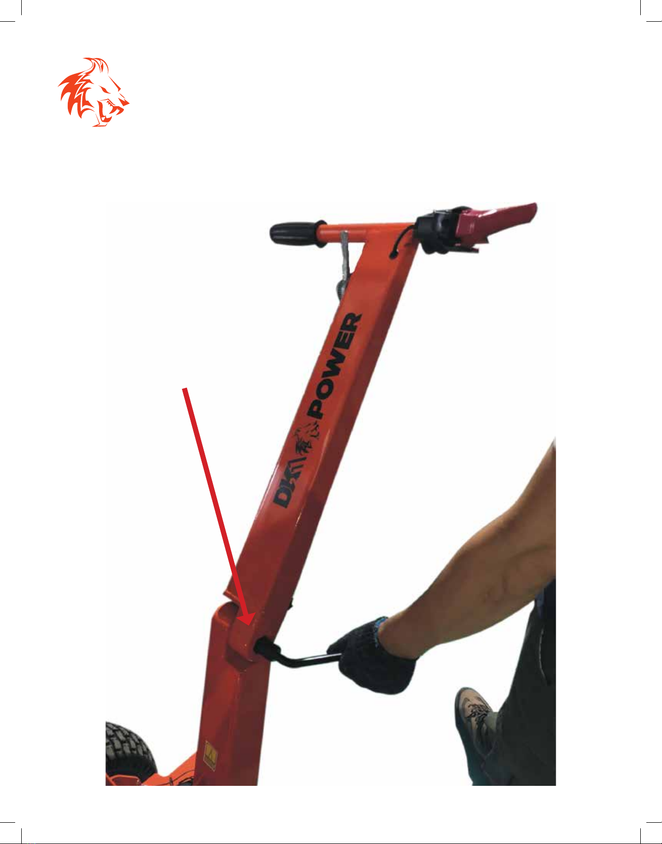
Depth control handle ................................................................................................................................................... 5
Chain drive bar............................................................................................................................................................... 6
Chain installation........................................................................................................................................................... 7
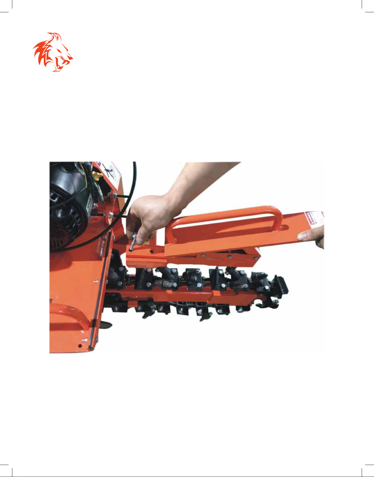
Safety bar installation................................................................................................................................................... 8
Auger guard.................................................................................................................................................................... 9
Engine operation, safety and maintenance ........................................................................................................... 10
SCHEMATICS AND PARTS
Chain system.................................................................................................................................................................. 11
Gear system.................................................................................................................................................................... 12
Drive system................................................................................................................................................................... 13
Depth control system................................................................................................................................................... 14
Main frame ...................................................................................................................................................................... 15
Ratchet assembly.......................................................................................................................................................... 16
Complete assembly...................................................................................................................................................... 17
Parts list............................................................................................................................................................................ 18
OPERATION
Before starting ............................................................................................................................................................... 19
Quick start and troubleshooting................................................................................................................................ 20
Warranty........................................................................................................................................................................... 21

3
STEP 1
CHECK THE PACKING
1. Open and unpack all items. Leave lots of working space.
2. Inspect all parts.
The Trencher is shipped in a crate. Leave the sides folded down and use as your work
space.
NOTE: UPON INSPECTION OF PARTS, IF YOU FIND ANY DAMAGE OR MISSING PIECES
PLEASE CALL DK2 POWER AT 702-331-5353 OR CONTACT US VIA OUR WEBSITE
WWW.DK2POWER.COM.
WE WILL REPLACE ANY MISSING PARTS TO YOU FOR FREE.
PLEASE DO NOT RETURN TO THE STORE.
STEP 1

4
STEP 2
HANDLE ASSEMBLY
1. Assemble the handle first.
STEP 1
INSTALL with hardware that is
supplied for the handle

5
STEP 3
DEPTH CONTROL HANDLE
1. Attach the depth control handle.
Turn handle to adjust depth

6
STEP 4
CHAIN DRIVE BAR
1. Slide chain drive bar onto support as shown. The cap head bolts will be tightened
later after the chain is installed.
Adjust bar even after chain install

7
LEAVE 1 INCH SLACK
STEP 5
INSTALL THE CHAIN
STEP 1: PLACE THE CHAIN ON SPROCKETS
STEP 3: INSTALL CHAIN PLATE JOINT
STEP 5: FINISH BLADE HOLDER INSTALL
STEP 2: INSTALL THE CHAIN PLATE
STEP 4: INSTALL CHAIN PLATE WITH PINS
STEP 6: TIGHTEN ALL BOLTS

8
STEP 6
INSTALL SAFETY BAR
1. Install safety bar with 2 bolts provided in the mounting holes

9
STEP 7
AUGER GUARD
1. Install the auger guard with bolts provided in the mounting holes.

10
STEP 8
ENGINE OPERATION, SAFETY & MAINTENANCE
1. Install the auger guard with bolts provided in the mounting holes.
1
2 73
4 6
5
1SAFETY SHUTOFF
2GAS - USE MID-GRADE OR HIGHER
3CHOKE - LEFT IS ON / RIGHT IS OFF (RUN POSITION)
4GAS ON/OFF SWITCH - LEFT IS OFF / RIGHT IS ON
5THROTTLE - RABBIT FAST / TURTLE SLOW
6PULL STARTER - PULL TIGHT, THEN PULL START
7OIL - FILL TO MARK 10W30, WILL NOT START IF OIL IS LOW, HAS LOW OIL
SHUTOFF PROTECTION. 2 YELLOW CAPS ARE OIL FILL CAPS. USE EITHER ONE TO
FILL OIL.

11
No. Specification No. Specification
1 main frame 8 gear cap
2 chain axle plate 9 chain spacer
3 chain lock 10 6204 bearing
4 cotter pin 11 front gear
5 blade 12 M20 nut
6 chain 13 chain adapter
7 M20 bolt 14 chain cover
70 chain cover bracket 78 square pipe for chain
77 square steel for chain 79 blade
SCHEMATICS & PARTS
CHAIN SYSTEM

12
SCHEMATICS & PARTS
GEAR SYSTEM
No. Specification No. Specification
1 main frame 22 taper bearing flange spacer
2 chain axle plate 23 taper bearing upper part
15 ridge 24 taper bearing base
16 ridge spacer 25 70 seal
17 back gear 26 72 outer circlip
18 gear axle 27 taper bearing spacer
19 8*7 keyway 28 gear wheel
20 8*7 keyway 29 M30 screw nut
21 35 outer circlip

13
No. Specification No. Specification
1 main frame 34 pulley
11 front gear 35 5*5 keyway
28 gear wheel 36 pulley axle
30 drive chain 37 bearing
31 clutch 38 bearing cover
32 belt 80 aligning block for bearing with seat
33 belt cover
SCHEMATICS & PARTS
DRIVE SYSTEM

14
SCHEMATICS & PARTS
DEPTH CONTROL SYSTEM
No. Specification No. Specification
1 main frame 82 support chip (left right)
2 chain axle plate 83 spacer
4 cotter pin 84 swing arm
43 pin 85 adjust rod outer tube
44 shift rod 86 trapezoidal screw
65 depth control handle 87 6002 bearing
81 rotating block 88 bearing tube

15
No. Specification No. Specification
1 main frame 50 20 washer
45 handle cover 51 wheel
46 throttle cable 52 butter bean
47 upper handle 53 angle arm
48 M16 bolt 54 flameout switch
49 lower handle 71 M20 nut
72 ridger protection rack 82 support chip (left right)
SCHEMATICS & PARTS
MAIN FRAME

16
SCHEMATICS & PARTS
RATCHET ASSEMBLY
No. Specification No. Specification
2 chain axle plate 58 pin
4 cotter pin 59 M10 nut
13 chain adapter 60 halt frame
55 M12 bolt 61 spring
56 M12 nut 64 M10 headed screw
57A ratchet wheel right 90 M10 x 30 screw
57B ratchet wheel left

17
SCHEMATICS & PARTS
COMPLETE ASSEMBLY

18
SCHEMATICS & PARTS
FULL PARTS LIST
No. Specification No. Specification
1 main frame 45 handle cover
2 chain axle plate 46 throttle cable
3 chain lock 47 upper handle
4 cotter pin 48 M16 bolt
5 blade 49 lower handle
6 chain 50 20 washer
7 M20 bolt 51 wheel
8 gear cap 52 butter bean
9 chain spacer 53 angle arm
10 6204 bearing 54 flameout switch
11 front gear 55 M12 bolt
12 M20 nut 56 M12 nut
13 chain adapter 57 ratchet wheel
14 chain cover 58 pin
15 ridge 59 M10 nut
16 ridge spacer 60 halt frame
17 back gear 61 spring
18 gear axle 62 M10 nut
19 8*7 keyway 63 M10 bolt
20 8*7 keyway 64 M10 headed screw
21 35 outer circlip 65 depth control handle
22 taper bearing flange spacer 67 M8*45 hexagon
23 taper bearing upper part 68 M8*20 hexagon
24 taper bearing base 69 start wire fixator
25 70 seal 70 chain cover bracket
26 72 outer circlip 71 M20
27 taper bearing spacer 72 ridger protection rack
28 gear wheel 77 square steel of chain
29 M30 screw nut 78 square pipe of chain
30 drive chain 79 blade
31 clutch 80 aligning block for bearing with seat
32 belt 81 rotating block
33 belt cover 82 support chip (left right)
34 pulley 83 spacer
35 5*5 keyway 84 swing arm
36 pulley axle 85 adjust rod outer tube
37 bearing 86 trapezoidal screw
38 bearing cover 87 6002 bearing
43 pin 88 bearing tube
44 shift rod 90 M10*30 screw

19
OPERATION
BEFORE STARTING
Clear area of all people and property that could be damaged. THINK SAFETY. Stones
from the soil can be projectiles and can cause injury. Wear safety glasses, hearing
protection, and gloves.
DO NOT wear loose fitting clothes that could get stuck in the machine’s moving parts,
only trench soil and sand.
Children SHOULD NOT run this equipment, stay alert of your surroundings and persons
that could appear in the digger path while you are working.
NEVER APPROACH AUGER OR CHAIN WHILE RUNNING - TURN TRENCHER OFF.
BEFORE YOU DIG, HAVE THE AREA VERIFIED FOR ANY UTILITIES IN THE GROUND.
BURIED ELECTRICAL LINES, GAS LINES, ETC.
Pull the unit back, lower the cutting chain to the desired depth, there are multi levels set
by the hand crank lever.
Make sure the forward brake is lowered into the wheel brake gears. Loosen the center
bolt in the brake bar to set the FORWARD brake system before digging. This will hold
your trencher from moving forward while digging. The unit will roll free in reverse pull.
Tighten the bolt to release the dual wheel brakes so your unit will roll freely for
transportation.
PERFORMANCE OPERATION
Your trencher has quick change teeth. The digger points snap out by tapping with
a hammer and replacements snap back into the socket. Use a block of wood when
replacing the teeth. Never strike the cutting tips with a hammer.
ALL PARTS ARE AVAILABLE FROM DK2POWER AT 702-331-5353

20
OPERATION
QUICK START & TROUBLESHOOTING
QUICK START SETUP
• Add 10W30 oil to engine
• Add gas
• Safety check area and use safety glasses, gloves, ear protection
• Lock hand safety shut o
• Half throttle (choke optional for cold starts)
• Pull start the engine
TRENCHING
• Set the forward wheel brake bar
• Crank chain o the ground and pull start the engine
• Throttle engine on highest speed
• Lower trencher chain slowly into ground for first cut
• Pull trencher backward as it trenches and the auger removes dirt
TROUBLE SHOOTING
ENGINE WON’T START
• Press the safety shuto switch and lock it - check engine oil level - check gas level
• Follow your engine manual for further trouble shooting
UNIT VIBRATES
• Check your chain for missing teeth or loose digger cleats
• Check your chain and auger for obstructions
• You may be into a big buried rock or tree root - inspect the trench
Other manuals for OPT118
1
Table of contents
Languages:
Other DK2 Power Chipper manuals

DK2 Power
DK2 Power OPC505AE Guide

DK2 Power
DK2 Power OPC505AE User manual

DK2 Power
DK2 Power OPC505AE User manual

DK2 Power
DK2 Power OPC525 User manual

DK2 Power
DK2 Power OPC506 User manual

DK2 Power
DK2 Power OPC503 User manual

DK2 Power
DK2 Power OPC506 User manual

DK2 Power
DK2 Power OPC524 User manual

DK2 Power
DK2 Power OPC524 User manual

DK2 Power
DK2 Power OPC504 User manual