DL Manufacturing Smart Chock SC0650 User manual

01/24/2020 SCM008 - REV H 1
Smart Chock™
Models SC0650 thru SC0654
340 Gateway Park Drive
North Syracuse, NY 13212
Phone: 315-463-7348
Toll Free: 866-235-7468
Fax: 315-463-8559
Email: sales@dlmanufacturing.com
www.dlmanufacturing.com
A Product of

01/24/2020 SCM008 - REV H 2
Smart Chock™ Installation Guide
This manual is used for models SC650 through SC654 Series Smart Chock™ model types. Be sure
to check your smart chock model type before consulting or servicing. The control board is
programmed for each model’s function. The description explains the differenced between model
types. Each model is programed and configured specifically for desired functionality.
Model #
Part # Description
650 CS650
Standard Smart Chock
™
No options: No outlets or interlocks
651 SC0651
Powers & controls one outlet for dock light
Dock light turns off when door is closed
652 SC0652
Powers & controls two outlets
Dock light & fan turn off when door is close
653 SC0653
Powers & controls two outlets & interlocks
Electric/Hydraulic leveler
Dock light and fan turn off when door is closed
Leveler will not run when door is closed
654 SC0654
Powers & controls two outlets & interlocks
Pneumatic leveler
Dock light and fan turn off when door is closed
Leveler will not run when door is closed
Fan turns off when leveler runs
INTRODUCTION
ELECTRICAL RATINGS:
INPUT VOLTAGE 120 VAC to 240VAC
INPUT FREQUENCY 60 HZ /50HZ
MAXIMUM INPUT CURRENT 12 A
INPUT CURRENT WITH NO OUTLET(S) OR LEVELER LOAD <.5 A (MODEL 650)
MAXIMUM OUTLET(S) CURRENT 12 A
MAXIMUM LEVELER LOAD CURRENT (J7 OR J8) 12 A
OUTSIDE LIGHT BOX VOLTAGE 12 VDC
MAXIMUM OUTSIDE LIGHT BOX LOAD CURRENT 1.25 A (12 V POWER SUPPLY CURRENT LIMIT)
SENSOR VOLTAGE (J2, J3, J4 & J16) 12 VDC
MAXIMUM SENSOR CURRENT (J2, J3, J4 & J16) .2 A (J2, J3 & J4 PROTECTED BY PTC THERMISTOR)

01/24/2020 SCM008 - REV H 3
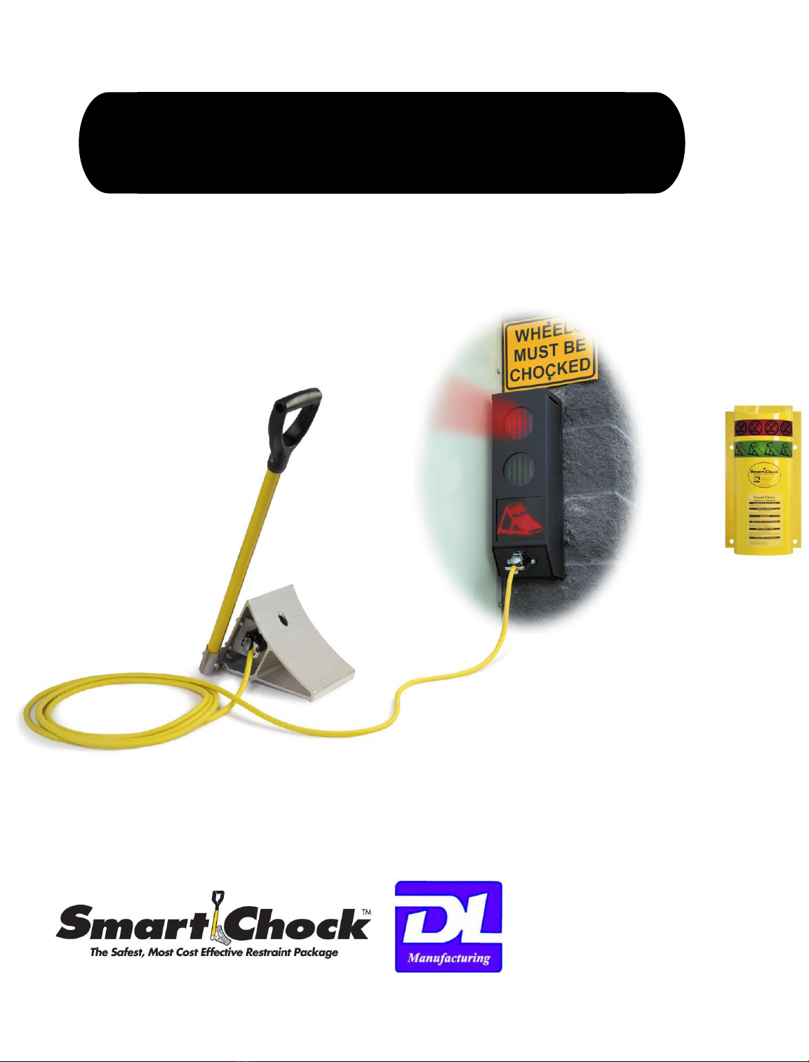
Smart Chock™
---Sequence of Operations---
Testing
POWER ON – Smart Chock enters a startup routine that turns the LED’s and Relays on and off a few times. The startup routine
runs for approximately 20 Seconds.
Loading Dock Door is Closed, Wheel is Unchocked
•Inside Red Light is on
•Outside Green Light is flashing
Wheel gets Chocked and after a 0 to 5 Second Delay
•Outside Red Chock Icon turns on
• Inside light changes from red to green “CHOCKED”
•Outside Green Light turns off
Door Open
•Outside top Red Light starts flashing
•Interlocks turn on –the outlets for a fan and dock light are enabled
(1) See note for Optional Sensor information
Door closes and after a (2) 5 to 15 Second Delay
•Outside flashing Red Light turns off
•Interlocks turn off –the outlets for a fan and dock light are disabled
Driver Removes Chock
•Outside Red Chock Icon turns off
•After a 5 to 15 second delay, Outside Green flashing light turns on
• Inside light changes from green “CHOCKED” light to Red Light
Safety Situations
*** Chock Pulled Prematurely with Door Open (After a (2) 3 to 15 Second Delay)***
• Inside light changes from green “CHOCKED” light to Red Flashing Light
•Versa Light® Dock Light flashes and Inside Audible Alarm Sounds for 5 minutes, fan outlet is disabled
•Interlocks are disabled
•Outside Red Chock Icon turns off, outside red stay on
•Outside Alarm turns on for 10 minutes
***Door opens without a truck wheel chocked***
•Versa Light® Dock Light flashes and Inside Audible Alarm Sounds for 5 minutes, fan outlet is disabled
•Interlocks are disabled
•Outside Red Chock Icon turns off, outside red stay on and Outside Alarm comes on for 10 Minutes
***Chock Cable gets Cut or Disconnected from Chock***
•Inside lights alternately flash from green to red, on board yellow system LED comes on
•Outside Red comes on and if wheel was chocked, Chock Icon turns off and Outside Alarm comes on for 10 Minutes
•Interlocks are disabled
•Inside Alarm turns on and does not turn off until power is turned off or cable is plugged back in
(1) An Optional Second Sensor can be connected to the Control Board at J3 or OPT2 (See page 12 for connection information). The Optional
Second Sensor negates the actions caused by the Door Sensor when the Door is Open. The Outside Red Light, Interlocks and Outlets are
turned off.
(2) At the core of the Smart Chock Control Board is an embedded microcontroller. Under preprogrammed control, the Smart Chock Time
delays, Light Outputs and Relay Outputs can be modified to suit any Customers individual needs. For example, the Time Delays could be
preprogrammed anywhere from 3 to 15 seconds.
Smart Chock™ Installation Guide

01/24/2020 SCM008 - REV H 4
Smart Chock™ Installation Guide
WARNING!!!! Do not use in hazardous or corrosive environments!
REQUIRED TOOLS
❑Drill bits, masonry bit for tap-con / wood bits 3/16” for pilot hole in dock seal
❑Tape measure Hammer Drill
❑Wire strippers Drill screw gun
❑Hammer Precision flat blade screwdriver 1/8” wide
❑Felt tip marker Wire labels
❑9/16” Wrenches for Chock Handle Assy.
INDEX
Description Page
COVER -
INTRODUCTION / ELECTRICAL RATINGS 2
SEQUENCE OF OPERATIONS 3
GENERAL INFO / INDEX / REQUIRED TOOLS 4
INSTALLER SUPPLIED HARDWARE & FASTENERS 5
CHOCK HANDLEASSEMBLY INSTRUCTIONS 6
VECTOR CHOCK ASSEMBLY INSTRUCTIONS 7
INSIDE LIGHT BOX MOUNTING 8
INSIDE LIGHT BOX MOUNTING CONTINUED 9
BOLLARD MOUNTING BRACKET (OPTIONAL) 10
PHOTO EYE INSTALL –TYPICAL & MxV DOOR 11
PHOTO EYE INSTALL –ROLLING STEEL DOOR 12
EXTERNAL BOX INSTALLATION 13
CONTROL BOARD WIRING OVERVIEW / INDEX 14
WIRING DIAGRAM J1 & J2 15
WIRING DIAGRAM J6, J7 & J8 16
INSIDE TO OUTSIDE BOX WIRING DIAGRAM J15 & J16 17
MODEL 650 SYSTEM WIRING DIAGRAM 18
651 SYSTEM WIRING DIAGRAM 19
652 SYSTEM WIRING DIAGRAM 20
653 SYSTEM WIRING DIAGRAM 21
654 SYSTEM WIRING DIAGRAM 22
OUTSIDE LIGHT BOX / CHOCK WIRING DIAGRAM 23
DL MANUFACTURING TERMS/CONDITIONS/WARRANTY 24
YEARLY MAINTENANCE
•Inspect inside connections for any damage
•Inspect mounting bolts for tightness
•Clean unit with compressed air
•Clean Photo Sensor Lenses
•Inspect chock cable for damage or wear
•Check chock handle for damage
•Clean chock & ensure of debris
•Check choc for corrosion of plug connections
•For chocks with yellow cords, be sure
connection is tight with channel-locks

01/24/2020 SCM008 - REV H 5
Smart Chock™ Installation Guide
Installer-supplied hardware & fasteners
Mounting Surface
Inside Light Box Outside Light Box
Cement Block (4) ¼” x 1¼” Tapcon (4) #10 x 1” Tapcon
Tip up concrete panel (4) ¼” x 1¼” Tapcon (4) #10 x 1” Tapcon
Sheet Metal Sheet metal walls are not thick
enough to hold inside box
Sheet metal walls are not thick enough
to hold outside box
Steel (4) ¼” x ¾” self-drilling screws 4) ¼” x ¾” self-drilling screws
Bollard Use DL Manufacturing supplied kit
Pole Bracket /
Chock Hanger
(4) 3/8 Dia. Concrete Anchors
Also needed:
Wiring –Outside Box to
Inside Box
7 conductor 18 gauge
wire
½” flexible conduit with
connector for 7/8 knockout
Field Notes:
FOR SERVICE ASSISTANCE CALL DL MANUFACTURING TOLL FREE 866-235-7468
Smart Chock Model #:___________________________________________
Smart Chock Serial #:
(LOCATED LOWER PORTION OF CONTROL BOARD)_______________________________________________________
Door Location:_________________________________________________
Customer:_____________________________________________________
This manual suits for next models
4
Table of contents
Popular Automobile Accessories manuals by other brands

ULTIMATE SPEED
ULTIMATE SPEED 279746 Assembly and Safety Advice

SSV Works
SSV Works DF-F65 manual

ULTIMATE SPEED
ULTIMATE SPEED CARBON Assembly and Safety Advice

Witter
Witter F174 Fitting instructions

WeatherTech
WeatherTech No-Drill installation instructions

TAUBENREUTHER
TAUBENREUTHER 1-336050 Installation instruction