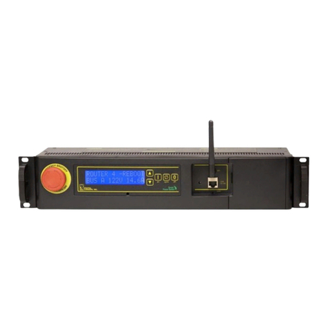
DLI DLM-4 ZONE User manual

DLM-4 ZONE
Controller

DLM-4 ZONE DLM-4 ZONE
Controller Controller
02 03
PLEASE READ FIRST
À LIRE EN PREMIER LIEU
1. Introduction
CONTENTS
BEFORE attempting to install of use this product, it is important to
read and fully understand this instruction manual. It will provide
detailed instructions and guidelines that will help to set up the unit,
and to understand the full capability of this unit. Observe all local and
national electrical codes and only install this unit as allowed in your
area. Any use or application of this product, other than for its original
intended purposes are prohibited. If you have any questions, please
contact us: Dutch Lighting Innovations, Kraaiendonk 22, 5428 NZ
Venhorst, The Netherlands
AVANT de tenter d’installer ou d’utiliser ce produit, il est important
que vous lisiez soigneusement le manuel d’instructions. Ce dernier
contient des informations détaillées et des directives permettant
d’installer l’unité et d’en comprendre toutes les capacités. Observez
toutes les règlementations électriques locales et nationales, et
installez l’unité conformément aux règles en vigueur dans votre
région. Toute utilisation ou application de ce produit à d’autres
fins que celles d’origine est entièrement interdite. Si vous avez des
questions, n’hésitez pas à nous contacter: Dutch Lighting Innovations,
Kraaiendonk 22, 5428 NZ Venhorst, The Netherlands
The DLM-4 Zone Controller is specially designed to set up a Daily
Lighting Management system for your Dutch Lighting Innovations
fixtures. The controller is equipped with an easy to use menu system
in six languages (English, Spanish, German, Dutch, French and
Mandarin).
The DLM-4 Zone Controller can be connected to up to 4 separate
zones of DLI lighting fixtures. Each zone can control up to 255 lights
and 1 sensor, so in total you can control 1020 lights and 4 sensors.
Once connected to the HIDs, the controller will monitor and control
(Turn ON and OFF) the lights using a digital timeclock. Up to (4)
separate temperature sensors can be connected that will measure the
temperature of up to (4) zones / growing areas. The user can select to
dim the lights if the temperature goes above their chosen setpoint, or
to turn the lights off.
1. Introduction
2. Facts
3. Components
4. Installing the DLM-4 Zone Controller
5. Determining the Zones
6. Connections
7. Set-up and using your DLM-4 Zone Controller
7.1 Start Settings
7.2 Configuration page
7.3 Main menu page
7.4 Zone setting page(s)
7.5 Zone status page
7.6 Temperature Min-Max
7.7 Manual OverRide (Force) page
7.8 To manually OverRide / Force a Zone:
7.9 Factory Reset
7.10 Firmware update page
7.11 Messages / Data Log
7.12 Power monitoring
7.13 Hot-start prevention
7.14 Dimming and high-temperature shut down
8. General Information
8.1 Warranty
8.2 Registration
9. Troubleshooting
03
04
05
06
07
09
12
13
14
15
16
18
19
20
21
22
24
27
27
28
29
30
30
31
32
Daily Lighting Management
DLM-4 Zone
BAck enter
Welcome to
Daily Lighting
Management
Press "Menu" to
configure your
DLM-4 Zone
Controller
Daily Lighting Management
DLM-4 Zone
BAck enter
01/19/17
Zone 1
1000W
Zone 2
Restrike
Zone 3
Restrike
Zone 4
Restrike
1000W70.7F
1000W Day
---.--F
14.31
---.-F
14:31
---.-F
14:31

DLM-4 ZONE DLM-4 ZONE
Controller Controller
04 05
3. Components2. Facts
Here are some important things to consider when using the DLM-4
Zone Controller.
A maximum of 255 ballasts and 1 temperature sensor can be
connected to each zone on the DLM-4 ZONE.
A maximum distance of 1000ft / 300 meters between the DLM-4
ZONE and the ballasts to be controlled.
Each zone MUST have a single wattage / type of fixture connected
to it. You cannot mix fixtures with different wattages on the same
zone interconnect wiring.
A single low-volt cable is used to interconnect the DLM-4 ZONE
to the fixtures within each zone. Various length pre-crimped RJ12
cables and additional interconnect splitters can be purchased
separately.
Ballast control is connected using RJ12 cables which are used to
daisy-chain the fixtures together. Each of the ballasts comes with
an RJ12 “T” splitter.
Each individual zone can have its own temperature sensor for more
accurate control.
It is also possible to “assign” a specific temperature sensor to link
with more than one lighting zone.
Each temperature sensor can be connected anywhere within the
growing area. Temperature sensors are connected using the same
RJ12 cables and “T” splitters.
Follow all local and national electrical codes for installation
requirements.
•
•
•
•
•
•
•
•
•
Controller
Back Plate
Screws and anchors for back plate and temperature sensor
16 ft RJ12 cable
4 ft RJ12 cable
Temperature sensor
T splitter
12 VDC Power supply
1
2
3
4
5
6
7
8
1 2
3
5
8
4
67

DLM-4 ZONE DLM-4 ZONE
Controller Controller
06 07
ZONE 1ZONE 1ZONE 1
ZONE 2ZONE 2ZONE 2
ZONE 3ZONE 3ZONE 3
5. Determining the Zones
4. Installing the DLM-4 Zone
Controller
Determine where to locate the main controller. The controller comes
with a simple to use DIN type bracket. Pull the 4 tabs outward to
release the bracket from the unit, mount the bracket to a wall or
surface, place the unit back on the bracket and press the 4 tabs back
in to lock the unit in place.
The interconnecting RJ12 communication cables are available in
different lengths, select the correct length for your application. The
DLM-4 Zone Controller is supplied with a 4ft and 16ft cable. These
interconnecting RJ12 cables are also available in lengths of 25ft and
50ft. Select the correct length for your application.
Release /
pull out (4) tabs
Installation of the DLM-4 Zone Controller starts by first designing
the DLI fixtures layout and the DLI fixtures will be connected to the
controller. Each zone can have separate dimming actions to take
place, and each zone can have it own separate temperature sensor
that monitors the zone temperature. All of the zones are controlled
individually based on the 24-hour timeclock built into the DLM-4 Zone
Controller.
Having 4 zones allows the user to create multiple lighting layouts (and
dimming sequences) based on their individual preferences. Some
examples are shown below.
Each zone can be set up to be a “staged” dimming zone. In other
words, each zone has it own independent dimming temperature
setting as well as the dimming action.
The example in the above left box shows 2-zones of lights in a
“Checkerboard” pattern. In this example zone 2 may be set to dim at
a slightly lower temperature than zone 1 would be set for. That will
create a “Staged” dimming control function where zone 1 will continue
to operate at full power while only zone 2 lights are dimmed.
The example in the above right box shows 3-zones of light set up in
a line. Each zone can have independent temperature sensors and
separate dimming settings.
ZONE 1
ZONE 1
ZONE 1
ZONE 1
ZONE 1
ZONE 2
ZONE 2
ZONE 2 ZONE 2

DLM-4 ZONE DLM-4 ZONE
Controller Controller
08 09
6. Connections
Installation is simple once you understand how the DLM-4 Zone
Controller is connected to the fixtures. Please review the “Determining
HID Zones” section below and ensure that you have already
determined how your lighting zones will be laid out.
Extra interconnecting RJ12 communication cables can be purchased
in lengths of 25ft or 50ft. Select the correct length for your application.
(in below drawing the correct picture of the fixture)
DLM-4 Zone Controller cables are made specifically for use with
the DLM-4 Zone Controller. Other cables will not work properly and
improper operation may result.
The temperature sensors can be connected ANYWHERE within
the fixtures communication cabling. The temperature sensors send
information to the DLM-4 Zone Controller using the same cabling
to reduce installation and allow greater flexibility. To connect a
temperature sensor determine where the sensor will be located, and
then run a communication cable from the nearest ballast on that
zone, to the temperature sensor “T” connection.
*NOTE: ONLY use DLI cables and T-Splitters.
THIS BLANK LAYOUT GRID CAN BE USED TO DRAW THE
DESIRED PATTERN / LOCATION FOR THE FIXTURES.
Determining the Zones
Continued...
Once the lighting zones have been designed, the ballast can be
connected to the DLM-4 Zone Controller unit.
Each of the 4 available zones on the DLM-4 Zone Controller unit
will have a separate cable connection to connect to the fixtures
within each zone.
Simply connect a RJ12 cable to the desired zone connector on the
bottom of the DLM-4 Zone Controller, and then run the cable to
the nearest ballast to be controlled.
Each of the HID ballast is connected to the zone cabling using the
included cable “T” splitter and a short cable.
The splitter then connects the next ballast in line and repeats this
process until all of the fixtures are connected to the desired DLM-4
Zone Controller zone cable.
*NOTE: The temperature sensor for each zone can be connected
ANYWHERE along the zone cabling. The same type cable splitter is
used to connect the temperature sensor inline with the fixtures. The
signal from the temperature sensor communicates with the DLM-4
Zone Controller through the same cables that communicate with the
fixtures.
1
2
3
4
5
WARNING: DO NOT connect the power to the fixtures until all
of the settings are entered into the DLM-4 Zone Controller.
AVERTISSEMENT: NE branchez PAS l’alimentation sur les
accessoires tant que tous les paramètres n’ont pas été entrés
dans le régulateur de zone DLM-4.

DLM-4 ZONE DLM-4 ZONE
Controller Controller
10 11
6. Connections Continued... Only use DLM-4 Zone Controller cables
Connect the cable going from Zone 1 to the first ballast to be
connected. (Refer to image above)
Use the supplied “T” connector and short cable so that the first
cable can continue on to be connected to the next “T” (ballast)
to be connected. Repeat this process until all of the fixtures are
connected to the zone. *NOTE: Repeat process for the other zones
to be used.
*NOTE: The temperature sensors can be connected ANYWHERE
within the zone communication wiring. Only (1) temperature sensor
can be connected per zone.
If the temperature probe receives direct HID light, it can cause
premature dimming and inaccurate (high) temperature readings.
When positioning the temperature probes, shield them from
exposure to direct light.
The communication cables should now be connected in a “daisy-
chain” configuration so that each ballast is looped / jumped to the
next ballast. All ballast and the temperature sensors should be
connected to the zones before continuing the installation.
Verify that all of the fixtures connected to the DLM-4 Zone
Controller have been set to operate using the External control. Turn
the selector switch on the side of each of the ballast to the correct
position to allow the DLM-4 Zone Controller to control the ballast.
*NOTE: If the ballast selector switch is NOT positioned to allow
External (DLM-4 Zone Controller) control, the ballast will function
manually, without control.
DO NOT CONNECT THE POWER CABLES ON THE BALLAST UNTIL
THE
DLM-4 ZONE ZONE WIRING AND SET-UP IS COMPLETE.
Once all of the zone cables are connected, you should now be able
to verify the temperature sensors are sending data back to the main
DLM-4 Zone Controller unit. Connect the DLM-4 Zone Controller
to power and confirm the temperature sensors are connected by
viewing the Zone Status screen. (After the unit starts, press the
Enter button to display the Zone Status screen)
The final step is to continue to choose the settings for the DLM-4
Zone Controller. The following section will explain how to customize
the DLM-4 Zone Controller Zone for your set-up.
1
2
3
4
5
6
7
8
9
10
*NOTE: The temperature sensor for each zone can be connected
ANYWHERE along the zone cabling. The same type cable splitter is
used to connect the temperature sensor inline with the ballast. The
signal from the temperature sensor communicates with the DLM-4
Zone Controller through the same cables that communicates with the
fixtures.

DLM-4 ZONE DLM-4 ZONE
Controller Controller
12 13
Daily Lighting Management
DLM-4 Zone
BAck enter BAck enter
7. Set-up and Using Your
DLM-4 Zone Controller
The DLM-4 Zone Controller is extremely easy to use. The backlit
128x128 LCD display will provide the user with the current conditions
and access all settings. All settings are accessed by using the 6
pushbuttons on the front of the unit. The button functions are
described below.
MENU: The Menu button will change the display from one page to the
next page within the menus.
FIND: The Find button opens up the error log and minimum /
maximum temperature display pages.
BACK: The Back button goes backwards to exit the current menu
item.
UP / DOWN: The Up and Down buttons move the cursor up and down
through the menu items.
ENTER: The Enter button is used to open the menu item to be
changed as well as to accept and “enter” the new setpoint into
memory.
Familiarize yourself with the function of the 6 buttons on the front
of the DLM-4 Zone Controller in order to able to access settings, and
to better understand how to use the DLM-4 Zone Controller to its
greatest potential.
7.1 Start Settings
Once you have connected all of the Zone connections from the DLM-
4 Zone Controller to the fixtures, and connected and positioned the
temperature sensors in each zone, we can start using the DLM-4 Zone
Controller.
Connect the plug-in power supply to the power connector on the
bottom of the DLM-4 Zone Controller. The DLM-4 Zone Controller will
turn on and boot up.
If it is the first time you have used the DLM-4 Zone Controller, when
you power on the DLM-4 Zone Controller the Welcome screen / page
will be displayed.
*NOTE: Press Menu to first go to the Configuration page and begin
set-up.
MENU
FIND
BACK
UP
DOWN
ENTER
Welcome to
Daily Lighting
Management
Press "Menu" to
configure your
DLM-4 Zone
Controller

DLM-4 ZONE DLM-4 ZONE
Controller Controller
14 15
7.3 Main Menu Page7.2 Configuration Page
The DLM-4 Zone Controller unit has several configuration settings
that can be customized by the user, those settings are stored in
the Configuration page. Below is a description of the Configuration
settings.
Temperature: Select whether to display F or C for temperature
measurements
Time Format: Select between 12 hour (am/pm) or 24 hour mode
Date Format: Select between USA date display (month-day-year) or
International date display (day-month-year)
Current Time: The user can set the current time.
Current Date: The user can set the current date.
To change Configuration settings:
After DLM-4 Zone Controller configuration is complete, press the
“Back” button to return to main menu.
Press the Menu button and then scroll down the Configuration
page, press Enter to access the Configuration page.
Once the Configuration page is displayed, use the Up and Down
buttons to navigate to the desired setting.
Press Enter to highlight the desired setting.
Use the Up and Down buttons to adjust the line item to your
desired setting.
Pressing Enter will accept the change.
After Configuration is complete, pressing the Back button will
return to the Main Menu
1
2
3
4
5
6
From the Main menu, all of the other pages can be selected. You will
see that there are (4) separate pages for each lighting “zone” settings.
There is also the “OverRide” page, (to manually bypass / force each
lighting zone On or Off) and finally a “System Setup” page to access
the firmware and factory reset.
*NOTE: Each zone has separate settings, but the steps required to
make changes to the settings are the same for each zone.
Main Menu
Zone 1
Zone 2
Zone 3
Zone 4
Override
Configuration
System Setup
Configuration
Output Unit
Temperature
Time Format
Date Format
Time
Date
W
F
12h
USA
03:48:56pm
03/08/2017

DLM-4 ZONE DLM-4 ZONE
Controller Controller
16 17
7.4 Zone Setting Page(s)
Each of the 4 zones within the DLM-4 Zone Controller has a separate
page for that zone’s particular settings. The settings are described
below.
Wattage: Select the wattage of ballast that will be connected to this
zone. (Each zone can only have one type of ballast connected) Choose
between 1000, 600 and 315 watts.
Output Max: Select the wattage that you would like to operate the
fixtures in increments of 25 watts. The user can select any setting
between 600 watts and 1150 watts for the 1000 watt fixture. For the
600/750 fixture any setting between 400 watts and 825watts can
be selected. (The 315 watt fixture is pre-set at 315 watts) Each zone
can operate the fixtures connected to it at different power settings.
When the lights are running normally (without dimming) this setting
determines the wattage each zone will operate at.
*NOTE: The DLI 315 watt fixtures CANNOT be dimmed.
On at: This is the time of day that the lights for that zone will be turned
ON.
Off at: This is the time of day that the lights for that zone will be turned
OFF.
Dim at: The user can select the temperature that they want the
lights within each zone to dim. Dimming the lights will reduce the
heat-load within the growing area and lower the temperature within
the growing area. The DLM-4 Zone Controller provides a gradual
dimming from full power, down to approximately 60% power as the
temperature rises above the user’s “Dim At” setpoint. (Dimming occurs
over a 5’F differential from the Dim At setpoint)
*NOTE: The 315 watt ballast cannot be dimmed. The 315 watt lights will
ignore the Dim At setting and ONLY use the Stop At setting. .
Stop at: The user can select the “maximum” temperature that the
growing area can get to before shutting down the lighting zones. This
setting should normally be set at least 5’F up to 10 degrees F above the
“Dim at” setting. If the temperature continues to rise in the growing
area, the lights connected to each zone can be shut off to eliminate
overheating of the growing area.
Sun R/S time: The DLM-4 Zone Controller can simulate Sunrise and
Sunset. By slowly raising and lowering the lighting level (brightness)
Sunrise and Sunset can be simulated. The user can select whether
they want to use this feature or not by setting the Sun R/S time.
The user can select up to 30 minutes in 5-minute increments for
the Sunrise / Sunset feature. When the lights are turned on by the
timeclock, the lights will gradually brighten to simulate morning, and
when the lights are scheduled to turn off, they will dim to simulate
the setting Sun.
*NOTE: Using this function will NOT add additional Lights ON time to
the light cycle.
SENSOR “ASSIGN”: Each of the temperature sensors can be assigned
to separate control zones, or to multiple zones. Some users may want
to assign each sensor to separate zones, others will want to use a
single sensor to control multiple zones. Having the ability to assign
the temperature sensors to each zone allows much greater flexibility.
The user can select which temperature sensor will be assigned to each
zone within this setting.
*NOTE: It is recommended that each zone has a separate temperature
sensor for best / most accurate temperature measurements in large
areas.
The Zone setup allows the user to select how to display the ballast
watts of power as well as to “assign” a specific temperature sensor
to each zone. Below shows another example of how the Zone page
might look.
The user will set each individual zone up within the Zone pages. Once
all of the Zones are set-up, the unit is ready for operation.
Zone 1
Wattage
Output Max
On at
Off at
Dim at
Stop at
Sun R/S time
Sensor
1000W
1000W
08:00am
08:00pm
88F
93F
OFF
Zone 1

DLM-4 ZONE DLM-4 ZONE
Controller Controller
18 19
7.5 Zone Status Page
Once the DLM-4 Zone Controller has been installed and all settings
have been entered, the DLM-4 Zone Controller will constantly monitor
the air temperatures, ballast status and current Day or Night status
within each of the lighting zones.
The measured temperatures are displayed on the Zone status menu
which also displays the current status of the DLM-4 Zone Controller
controlled zones.
The Zone Status menu will be displayed unless there is an event /
error that occurred. If an event is being displayed, pressing Enter will
acknowledge the event / error, and reset the event log.
Pressing the Menu button from the Zone Status menu will access the
Main menu.
*NOTE: When one temperature sensor is assigned to more than one
zone, that temperature sensor will display it’s information within ALL
zones that it is assigned to.
7.6 Temperature Min-Max Page
Pressing the Find button on the DLM-4 Zone Controller will access
some important functions. The first page that will be displayed is the
Temperature Minimum-Maximum page.
Each of the temperature sensors installed will constantly measure the
temperature and record the maximum (high) and minimum (low)
temperatures.
These recorded temperatures can be used to confirm that the cooling
/ heating systems inside the growing area are working properly.
The Min-Max recorded values will also verify that the growing area was
not subjected to damaging high temperatures above the DLM-4 Zone
Controllers dimming setpoints.
Once the recorded values have been viewed, the user can easily reset
the values (each day) by pressing the Enter button. Pressing Enter will
rest the recorder values and begin to store new values that can be
viewed the next “day”.
03/08/2017
Zone 1
Restrike
Zone 2
Restrike
Zone 3
Restrike
Zone 4
Restrike
1000W67.2F
09:03
---.-F
09.03
---.-F
09:03
---.-F
09:03
ENTER to Reset
Zone 1
Zone 2
Zone 3
Zone 4
Max
Min
Max
Min
Max
Min
Max
Min
F
F
F
F
F
F
F
F
68.1
66.9
---.-
---.-
---.-
---.-
---.-
---.-

DLM-4 ZONE DLM-4 ZONE
Controller Controller
20 21
7.8 To Manually Override /
Force a Zone:
*NOTE: To disable / cancel the OverRide / force function, simply
change the “√” back to an “×”
When the OverRide menu is displayed, use the Up and Down
buttons to move the cursor to the Zone # that you want to force
On (or Off).
Press Enter to access the Zone setting.
Use the Up or Down button to change the “×” to a “√”
Pressing Enter will force the Zone On (or Off)
The Zone countdown shows the current output status and at the time
remaining before changing the ON/OFF status.
1
2
3
4
OVERRIDE / FORCE PAGE
Override
Zone
Force
Zone
1
X
2
X
3
X
4
X
1
2
3
4
ON
ON
ON
ON
04:09:07
04:09:07
04:09:07
04:09:07
Countdown
7.7 Manual OverRide
(Force) page
Occasionally the user may want to manually turn each lighting Zone
On or Off manually. Each of the 4 zones within the DLM-4 ZONE
controller can be manually activated (turned ON or OFF) by accessing
the Manual over-ride page. When a zone is manually “forced” on or
off, the force will remain in effect until the next scheduled on or off
cycle for that zone. (Force is automatically reset once next timed event
occurs)

DLM-4 ZONE DLM-4 ZONE
Controller Controller
22 23
7.9 Factory Reset
The unit comes from the factory pre-programmed with common
settings. The unit can be returned to it’s original factory default
setpoints at any time. Access the Configuration menu and open the
Factory Reset menu item, pressing Enter a second time will reset the
unit to factory settings.
*NOTE: ALL CURRENT USERS SETTINGS, TEMPERATURE AND EVENT
LOG DATA WILL BE LOST.
To reset the setting to factory presetting, select the “System Setup”
page in the Main menu and then select “Factory Reset”
Pressing Enter will bring you the Factory Reset confirmation page, you
will be asked to confirm the Factory Reset (press Enter) or to press the
Back button to cancel the reset and return to the previous page.
FACTORY RESET PAGE
System Setup
Factory Reset
Firmware Update
Firmware: V_2.7
SN:001EC0FAE110
Pressing “Enter”, will reset the DLM-4 Zone Controller to the factory
settings and automatically return to “System Setup” menu page.
7.9 Factory Reset Continued...
Press "ENTER"
again to reset
all log data and
configurations
Press "BACK" to
return to
previous menu

DLM-4 ZONE DLM-4 ZONE
Controller Controller
24 25
7.10 Firmware Update Page
Occasionally the DLM-4 Zone Controller may release updated
firmware / software for the DLM-4 Zone Controller. The new firmware
may update older versions firmware, or add new functions to the DLM-
4 Zone Controller. To update the firmware:
First visit www.dutchlightinginnovations.com to find out what
the most recent version of the firmware is available for download.
On the DLM-4 Zone Controller unit, select the System Setup page.
The current firmware version will be shown at the bottom of the
display. If the firmware needs to be updated, follow the prompts
on the computer to download a copy of the newest firmware onto
a MicroSD card.
Insert the MicroSD card into the slot on the bottom of the DLM-4
Zone Controller unit.
Access the Firmware Update menu by going back to the System
Setup menu and scrolling down to Firmware Update.
Press the Enter button to enter the firmware update menu.
Press Enter to scan the SD card files.
1
2
3
4
5
6
7
*NOTE: If the scan does not find any firmware (BIN files), the display
will show the following message.
7.10 Firmware Update Page
Continued...
Press "ENTER"
again to enter
Firmware update
menu
Press "BACK" to
return to
previous menu
Scan end
BIN file
quantity is 002
Scan end
BIN file
quantity is 000
Can not find
BIN file for
DLM-4 Zone
Controller
Scanning SD card
Please wait...

DLM-4 ZONE DLM-4 ZONE
Controller Controller
26 27
If the scan is successful, the available firmware file(s) will be
displayed. Move the cursor to the newest version of the firmware to
be installed.
8
Select the file to be updated.
Press the Enter button.
Verify the displayed firmware file update is correct on the display.
Press the Enter button to update the firmware.
When the update is completed, the unit will reset, and return to
the Zone status menu.
9
10
11
12
13
*NOTE: The user data will NOT be over-written when the firmware is
updated.
*NOTE: If the scan does not detect the MicroSD card, the display will
read:
Warning:
No SD card
detected
Please
insert SD card
7.11 Messages / Data Log
If there is a dimming event, or a power failure event, a message
including details including time and date of the event, temperature
recorded, and a description of the event will be created by the DLM-
4 Zone Controller and stored within memory to be viewed later. The
controller can record and store a total of 10 events.
The messages are accessed by pressing the Find button to display the
stored messages, and then pressing the Enter button in order to clear
/ reset the message log.
MESSAGES / DATA LOG MENU
7.12 Power Monitoring
The DLM-4 Zone Controller is constantly monitoring the power going
to the DLM-4 Zone Controller. When power is re-applied to the DLM-4
Zone Controller, the unit will start up and display the Power Failure
error. The unit will show the time that the power turned off, and the
time the power turned back on.
*NOTE: To return to the Zone status menu, press the ENTER button.
Power failure
04:07:25pm
03/08/2017
Power On
04:07:41pm
03/08/2017
ENTER to Return
Update code is
DIMMER
VER 3.2
Chip code is
DIMMER
VER 3.1
Update ?

DLM-4 ZONE DLM-4 ZONE
Controller Controller
28 29
7.13 Hot-start Prevention
If power is interrupted to the DLM-4, the unit will restart the lights after
a 15 minute time delay to allow the lamps to cool before re-starting.
Each successive zone re-start will be preceded by a 5 second delay in
order to reduce electrical startup surges / loads. During the 15-minute
delay, the DLM-4 will show the time remaining until the lights will be
re-started, (turned On).
*NOTE: In order to minimize start-up load or high power “spikes”, after
a power outage each one of the 4-zones will be re-started sequentially.
After the first zone re-starts, a 5-second “cascading timer” delay will
begin for each of the remaining 3-zones to turn back on 1 at a time.
*NOTE: While the time delay is counting down, the Zone status menu
will display the time remaining, before the lights are allowed to re-
strike.
01/19/17
Zone 1
1000W
Zone 2
Restrike
Zone 3
Restrike
Zone 4
Restrike
1000W70.7F
1000W Day
---.--F
14.31
---.-F
14:31
---.-F
14:31
7.14 Dimming and
High-temperature Shut Down
The DLM-4 Zone Controller has the ability to monitor the temperature
of 4-separate zones. The user can select their desired dimming and
high-temp shut down (Stop At) settings within the zone settings.
Dim at setting: If the temperature of any of the zones being monitored
rises too high, the lights connected (assigned) to that zone will be
dimmed to reduce the temperature inside the growing area.
Stop at setting: If the temperature continues to rise, and the “Stop
At” temperature setting is reached, the lights within that zone will be
turned off.
*NOTE: The zones will return to normal operation automatically once
the temperature is reduces by 2’C / 3.6’F below the dimming and the
Stop At setting. (The dimming or high-temp shutdown event will be
stored in memory within the error log menu.
*NOTE: To return to the Zone status menu, press the Enter button.
Zone 1
Dimming start
04:41:25pm
03/08/2017
Temp: 70.8F
ENTER to Return

DLM-4 ZONE DLM-4 ZONE
Controller Controller
30 31
8. General Information
8.1 Warranty
WARRANTY
RETURNS
RETOURS
Dutch Lighting Innovation only uses high quality components.
Under normal operating conditions, the mechanical and electronic
components are covered by a three-year warranty from the original
date of purchase. For service return the DLM-4 Zone Controller in the
original packaging to your shop with the original sales receipt.
Components that are excluded from warranty are components that
have failed due to abnormal usage.
In the case of defects of the DLM-4 Zone Controller, the Controller will
either be replaced or repaired using new or reconditioned products or
parts. If the Controller will be replaced this limited warranty shall apply
to the replacement product for the remaining initial warranty period,
i.e. (three) 3 years from the date of purchase of the original product.
All returns need to be done in the original packaging in order to avoid
damages of the product during transport. Defective products need
to be returned to factory or service shop for repaiir. Non-professionals
Do not open the cabinet to prevent electric shock or damage to the
equipment
Pour tout retour, le produit doit être replacé dans son emballage
d’origine afin d’éviter qu’il soit endommagé pendant le transport.
Les produits défectueux doivent être renvoyés à l’usine ou à l’atelier
d’entretien pour réparation. Avis aux non professionnels: n’ouvrez pas
l’armoire afin d’éviter tout risque de choc électrique ou de dommages
matériels.
8.2 Register your Controller for
the Latest Software Updates
Dutch Lighting Innovations will occasionally release updated firmware
for the DLM-4 Zone Controller.
By registering your DLM-4 Zone Controller on our website
www.dutchlightinginnovations.com we can notify you when an
update is available.
We will not sell, rent or share your personal information.

DLM-4 ZONE DLM-4 ZONE
Controller Controller
32 33
9. Troubleshooting 9. Troubleshooting Continued...
Some of the most common issues or problems can be found within
this section. Before returning the unit for service, please consult the
troubleshooting points below, additional information can be found
online at www.dutchlightinginnovations.com
The DLM-4 Zone Controller is
connected to power, but it
does not seem to be working
/ no display
Check the low-volt power
supply is plugged in properly
to the DLM-4 Zone Controller.
After setting up the DLM-4
Zone Controller, the fixtures
are still not being turn on or
controlled.
Each ballast must be manually
switched to External (DLM-4
Zone Controller) control. Verify
the selector switches on the
ballast are correct.
The 315 watt fixtures cannot be
dimmed. However, they can be
turned OFF if the temperature
reaches the “Off At” setpoint.
Within each Zone settings,
you can select which
temperature sensor you want
to “assign” to that zone. Verify
the Sensor setting is correct.
Make sure the temperature
sensor is not receiving direct
HID light which would increase
the temperature reading.
The Zone does not seem
to be controlled by the
temperature sensor correctly.
The temperature display
within one or more zones
does not seem to be correct,
reading high.
Power was interrupted to the
unit, and now the lights will
not turn on.
There is a 15-minute time delay
after a power failure to prevent
the lamps from hot-starts.
The dimming function does
not work for my 315 watt
fixtures.
PROBLEM RESOLUTION
WARNING: DO NOT allow theDLM-4 Zone Controller to be
exposed to water or excessive heat. DO NOT open or attempt
to repair or disassemble the controller, as there are no user-
serviceable parts inside. Opening the controller will void the
warranty.
If the DLM-4 surface is dirty, wipe it with a dry towel.
The DLM-4 operates under natural ventilation conditions.
AVERTISSEMENT: N’exposez PAS le régulateur de zone DLM-4
à de l’eau ou à une chaleur excessive. NE l’ouvrez PAS, NE tentez
PAS de le réparer ou de le démonter, car il ne contient aucune
pièce réparable par l’utilisateur. L’ouverture du régulateur
entraîne l’annulation de la garantie.
Si la surface du DLM-4 est sale, essuyez-la à l’aide d’un chiffon
sec. Le DLM-4 fonctionne sous des conditions de ventilation
naturelle.

DLM-4 ZONE DLM-4 ZONE
Controller Controller
34 35
ENVIRONMENTAL AND DISPOSAL CONCERNS:
THIS PRODUCT CONTAINS A BATTERY AND OTHER COMPONENTS
WHICH MUST BE DISPOSED OF PROPERLY.
This symbol displayed on a product, its accessories, or its
packaging indicates that this product may not be discarded
as household waste. Dispose of the equipment through
a recycling center that handles electronics and electrical
appliances. By disposing of the equipment in the proper and
lawful way you will be helping to prevent possible damage to
the environment and risk to public health.
SPECIFICATIONS:
Voltage / power supply
Tension/ Alimentation électrique
Degree of ingress protection
Indice de protection
Certifications
Certifications
12vdc @ 200ma
12 V CC 200 mA
Backlit, 9 lines x 16 characters
1000 meters each zone
+/- 1 degree F
ETL / FCC
ETL / FCC
IP20
IP20
FOUR separate zones each with
separate temperature sensors
(1) Standard *Additional sensors
can be added up to (4) total
* Not limited = can be placed
anywhere inside growing area
Use between 0-45’C,
up to 80% rH non-condensing
Non-volatile, retained
145mmx75mmx50mm
256 per zone x 4 zones
= 1024 HIDs
Micro SD card (not included)
Battery backup >7 years CR
Dimensions
LCD Display
Number of lighting zones
Maximum number of HID fixtures
Temperature sensor cable length
Temperature sensor accuracy
Environmental considerations
External communications
External communications
Timeclock
Temperature sensor
Maximum distance to HIDs

www.dutchlightinginnovations.com
Table of contents
Other DLI Controllers manuals
Popular Controllers manuals by other brands
Leviton
Leviton vizia rf+ VRCZ4 installation instructions
Newlab
Newlab L526MA04R2A02 user manual
PI
PI N470 Series user manual
HEIDENHAIN
HEIDENHAIN ND 287 - 8-2010 operating instructions
Novus
Novus N1200HC instruction manual
Hornbach
Hornbach Activalve S468 Installation maintenance and operating instructions
