manuals.online logo
Brands
  1. Home
  2. •
  3. Brands
  4. •
  5. sauter
  6. •
  7. Controllers
  8. •
  9. sauter ASV115 Operational manual

sauter ASV115 Operational manual

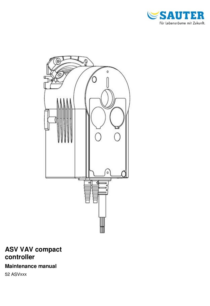
VAV compact controllers
PDS 52.100 en Product Data Sheet ASV115
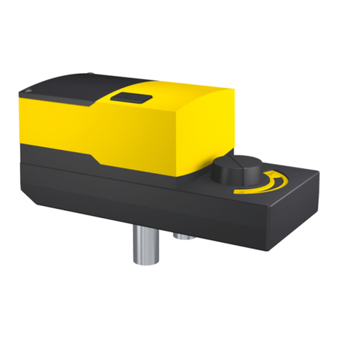
ASV115: VAV compact controller, standard version
How energy efficiency is improved
Provides demand-led control of the air volume to optimise energy consumption in ventilation systems. Differen-
tial pressures of up to 1 Pa can be controlled, providing very small air volumes with extremely low duct pressures
and energy consumption.
Areas of application
Controlling supply and exhaust air in, for example, offices, conference rooms or hotel rooms in conjunction with
an air volume box or a damper and a flow probe.
Features
Static measurement of differential pressure based on the capacitive method
Can be used in areas with dirty or contaminated exhaust air
High-precision measurement of differential pressures with ranges of up to 300 Pa
Variable running times from 30 to 120 seconds
Brushless DC motor provides the lowest possible energy consumption and a long service life
Electronic torque cut-off for safe operation
Easy to fit due to self-centring spindle adaptor
Transmission can be disengaged for manual adjustment and positioning of the damper
Power cable 0.5 m long, 10 0.32 mm², fixed to housing
Can easily be combined with RLE150F100 or NRT300
Fail-safe control for critical applications
RS-485 bus interface for up to 31 subscribers in a segment with SLC (SAUTER Local
Communication) protocol
Easy to parameterise using the SAUTER CASE VAV software
Constant air volume control using parameterisable inputs
Technical description
Power supply 24 V~/=
Variable end values for the differential pressure's measuring range:
50…150 Pa
100…300 Pa
Efficient control algorithm
Output signal 0…10 V for:
Air volume, actual value rq
Air volume, control deviation –eq
or for damper position r
Input signal 0…10 V for:
Command variable cq
Setpoint shift cq ad ()
Priority control via switch contacts
Zero point with calibration facility
Products
Type Torque 1) at 24 V~
(Nm)
Measuring range p (gain=1)
(Pa)
Power supply Weight
(kg)
Version with standard cable
ASV115CF132D 10 0…150 24V~/= 0.8
ASV115CF132E 10 0…300 24V~/= 0.8
Version with halogen-free cable
ASV115CF132I 10 0…150 24V~/= 0.8
ASV115CF132K 10 0…300 24V~/= 0.8
Technical data
Electrical supply Integrated damper size (continued)
Power supply 24 V~ ± 20%, 50…60 Hz Permissible size of damper shaft Ø 8…16 mm
24 V=
2) ± 20% 6.5…12.7 mm
Power consumption Permissible hardness of damper shaft max. 300 HV
at nominal voltage 50/60 Hz Resistance to transient voltages 500 V (EN 60730)
after a running time of 30 s 120 s Noise during operation < 30 dB(A)
in operation at 10 Nm (AC/DC) 5.7 VA/3.3 W 4.8 VA/3 W
when idle 3) (AC/DC) 4.2 VA/2.1 W 4.2 VA/2.1 W p sensor
Range p (gain = 1)
Integrated damper size Pressure range Type D & I/E & K 0…150/300 Pa
Running time for 90° angle of rotation 30…120 s 4) Non-linearity 2% FS
Angle of rotation 90° 5) Time constant 0.05 s
www.sauter-controls.com 1/13
ASV115
Technical data (continued)
psensor (continued) Interfaces, communication (continued)
Influence of position ± 1 Pa Length of cable
Reproducibility 0.2% FS without bus termination up to 200 m, Ø 0.5 mm
Zero point stability at 20 C 0.2% FS with bus termination up to 500 m, Ø 0.5 mm
Permitted positive pressure ± 10 kPa Cable type twisted pair 11)
Permitted operating pressure pstat ± 3 kPa 6) Bus termination > 200 m, 120 both sides
Air connection Ø i = 3.5...6 mm 7)
Permitted ambient conditions
Inputs Operating temperature 0…55 °C
AI01 analogue 0…10 V (Ri= 100 k) Storage and transport temperature -20…55 °C
AI02 analogue 8) 0…10 V (Ri= 70 k) Humidity < 85% rh
DI04 digital 9) closed < 0.5 V, 1.3 mA no condensation
open > 2 V~
DI05 digital 9) closed < 0.5 V~, 1 mA Installation
open > 3 V ~ Weight (kg) 0.8
Outputs Standards, guidelines and directives
AO03 analogue 0…10 V load > 10 kType of protection (horizontal) IP 54 (EN 60529)
AO02 Analogue 8) 0…10 V load > 10 kProtection class III (EN 60730)
Degree of contamination 2 (EN 60730)
Interfaces, communication
RS-485 not galv. separated 115 kBaud Additional information
Protocol SAUTER Local Communication (SLC) Fitting instructions MV 506011
Access method Master/slave CASE VAV manual 7010022001
Topology Line Material declaration MD 52.100
Number of subscribers 31/32 10)
Dimension drawing M10457
Wiring diagram A10519
1) Holding torque (not under power) due to self-locking in transmission system 1 Nm
2) Non-connected analogue inputs are valued at 0 V. The nominal torque is attained within the given tolerances. AI/AO can be used only as an input.
3) Holding torque > 10 Nm
4) Running time can be set via the software
5) Maximum angle of rotation 95° (without end stop)
6) Brief overload; the sensor's zero-point adjustment is recommended
7) Recommend hardness of tubes < 40 Sha (e.g. silicone)
8) Connection 02 can be configured as an analogue input or analogue output using SAUTER CASE VAV software
9) Digital inputs for external potential-free contacts (gold-plated recommended)
10) The parametering tool is always one of the subscribers, so a maximum of 31 devices can be linked
11) Recommended: Belden 3106A
Accessories
Type Description
0520450010* CASE VAV – USB connection set, incl. software
CERTIFICAT001 Manufacturer’s test certificate type M including p sensor calibration data
0372300001 Anti-torsion device, long (230 mm)
0372301001 Shaft adaptor for squared end (x 15 mm) hollow profile (pack of 10)
XAFP100F001* Dynamic-pressure sensor for measuring air volumes in ventilation ducts
*) Dimension drawing or wiring diagram is available under the same number
General description of operation
The differential pressure created on an orifice plate or a dynamic
pressure sensor is recorded by a static differential pressure sensor
and is converted into a flow-linear signal. An external command
signal cqis limited by the parameterised minimum and maximum
settings, and is compared with the actual air volume rq. Based on
the control deviation that is determined, the damper on the air
volume box is adjusted by the drive until the required air volume is
attained over the measurement point. Without an external com-
mand signal, the value for min that was specified in the parame-
terisation corresponds to command variable cqConfiguration of the
application and the internal parameters is software-based, using
SAUTER CASE VAV PC software.
The software supports the application-specific configuration of the
compact controller and the setting of the necessary parameters in
bus mode. The VAV compact controller is supplied ex factory with a
standard configuration. For this purpose, the inputs and outputs are
preconfigured as shown in the table.
2/13 www.sauter-controls.com
ASV115
Connection plan For configuration purposes, the specifications for the air volume box
must be loaded into the drive using SAUTER CASE VAV. The data
below are required for this purpose as a minimum.
Connection Colour coding Function
01 Red External command variable
Cq0…10 V 0…100% nom
2 Black Setpoint shift
Cq ad () 5 V ± 5 V ± 15%
03 Grey Actual value
Rq0…10 V 0…100% nom
04 Violet Priority control
min (activated condition)
05 White Priority control
max (activated condition)
Air volume specifications
DN
box
C factor
box
nAT nom max min
Unit mm l/s – m3/h l/s - m3/h l/s - m3/h l/s - m3/h l/s - m3/h
Abbreviations and symbols
nNominal air volume n AT Nominal air volume for air terminal
n effectiv Effective nominal air volume nom nominal in plant
max Maximum air volume mid Air volume between max and min
min Minimum air volume int Internal air volume
var Continuous air volume, e.g. corresponding to command
variable 0…10 V
p Differential pressure on the sensor in pascals
VAV Variable air volume CAV Constant air volume
cw Clockwise ccw Counter-clockwise
rqV Actual value as per IEC 60050-351 (former) Xi) cqV.s Command signal as per IEC 60050-351 (former Xs)
rFeedback signal for damper position as per IEC 60050-351 -eqV.s Control deviation for air volume as per IEC 60050-351
cqV.p.ad Command signal shift as per IEC 60050-351 (former ) cqV.p.2 Command signal as per IEC 60050-351 through switching
contact 2 (DI05)
cqV.p.1 Command signal as per IEC 60050-351 through switching
contact 1 (DI04)
Factory setting
FS Full scale PRRoom pressure
TRRoom temperature Heating
Cooling DN Nominal diameter
c/o Change-over
ad Index ad for additive
p Index p for 'priority' V Index V for air volume
s Index s for 'second priority'
q Index q for quantity
Setting the air volume
The following functions are generally available to operate the air volume controller.
Setting ranges
Function Air volume Maximum setting ranges Recommended setting ranges
Damper closed Damper fully closed 0° damper position
min Minimum 1Pa … max 10…100%
max
max Maximum 1Pa … nom 10…100%
nom
mid Intermediate position max > mid > min 10…100%
max
Damper open Damper fully open 90° damper position
nom Nominal air volume specific value, dependant on box type, air density and application
int Internal setpoint 1Pa … nom 10…100%
nom
Minimum and maximum air volume ( min and max) via command signal (AI01)
The min and max values, which should be parameterised using
software, impose an upper and a lower limit on the command signal
cqV.s. The values to be set for min and max are entered as either
percentages or absolute values. If absolute values are entered, the
plant-specific differential pressure values in pascals are calculated
using the equation below. Without an external command signal, the
set min value becomes the setpoint. Minimum and maximum air
volume values are overridden using digital inputs. In addition, the
setpoint is dependent on the logical status of the command variable
and the assigned forced operation.
Calculation of min and max
www.sauter-controls.com 3/13
%100*
V
V
(%)V 3
nom
3
min
min































h
m
h
m


%100*
V
V
(%)V 3
nom
3
max
max































h
m
h
m


10V
0
Vmin
Vmax
Vnom
100%
0
V
cqV.s
B11691
ASV115
4/13 www.sauter-controls.com
cqV.s
10V
100%
0
0
Vmin
Vmax
Vnom
0
5
10V
5
V
rqV
B11694
10V
100%
rqV
0
0
V
Vnom
B11693
damper position
Command signal cqV.s can be configured in various modes via the
software. Ranges 0…10 V, 2…10 V and free configurable are
available. This relates to the 0…100% nom range.
As standard, the following functions are specified by the factory
setting for 24 V~ operation of the controller.
Forced operation* AI01
Designation Range 0…10 V Range 2…10 V Function
NC = not connected -0.69 V -0.69 V min
LOW voltage -0.5…0.3 V -0.5…2.2 V Damper closed
NORMAL voltage 0.7…9.8 V 2.2…9.8 V Control range ( var)
HIGH voltage 10.2…11 V 10.2…11 V Control range ( var)
OVER voltage > 11.4 V > 11.4 V Damper open
*) Switching hysteresis is 0.4 V (4%) as the default value
Seepage suppression
In order to avert unstable control behaviour around the min, so-
called 'seepages' are suppressed automatically. This suppression
causes the damper to close if command variable (cqV.s) 6% of the
set nominal air volume.
Control resumes when the command variable (cqV.s) 7.8% of the
nominal air volume.
Functional diagram cqV.s
Feedback for damper position (AO02) and actual value for air
volume (AO03)
Three measured variables are generally available as a feedback
from the air volume control loop: damper position, air volume and
operating pressure. These values can be read with SAUTER CASE
VAV software in the Online monitoring mode.
Online monitoring
Damper position ° Angle of rotation 0…100% angle of
rotation
Actual air volume m³/h 0…100% nom
Operating pressure Pa 0…100% Pnom
The feedback signal for the damper position can be transmitted as
an analogue signal via terminal AO02. The value equates to
0…100% of the maximum permitted angle of the damper.
Functional diagram for damper position
The function can be set using Sauter CASE VAV 1.4 or higher,
which allows one of the following applications for the device to be
selected: VAV.10.001.M, VAV.20.001.M or VAV.20.001.Sxi. When
setting the parameters for terminal AO02 using the feedback signal
for the damper position, it is recommended to perform an adaption
using Manual mode – adapt angle of rotation. This determines the
angle between the 'closed' and 'open' damper positions.
In general, the actual value of the damper position is used for the
following functions:
Display on the BMS, for the purpose of monitoring the primary
pressure.
Fan control as a function of the various damper positions in the
installation.
In addition, the current air volume (actual value rqV) across the air
volume box is measured at terminal AO03. The value corresponds
to 0…100% of the set nominal air volume nom. If no specific plant
air volume is entered, nom corresponds to the value nAT set by
the box manufacturer, which can generally be found on the specifi-
cation plate of the air volume box.
Functional diagram for rqV
The form of output signal rqV can be configured in various modes
using the SAUTER CASE VAV software. Ranges 0…10 V, 2…10 V
and 'free configurable' are available.
The actual value signal and the command signal always relate to
the set air volume nom.
Note
Actual value signals from two or more controllers must not be
connected together.
The actual value signal for the air volume is generally used for the
following functions:
To display the air volume on the (BMS)
Master-slave application; the actual value signal from the master
controller is specified as the setpoint for the slave controller.
The actual value signal rqV can be used to calculate the current air
volume. For this purpose, the voltage is measured on output AO03
and is offset against the set nominal air volume.
ASV115
www.sauter-controls.com 5/13

 

25.6%40
0.20.10 %40%80
23*25.0[%]
1
12 12
1*[%] %
%%
..





















VV
VVshift
P
PP PP
PcFshift
UU
UadpqVS
%
10V
100%
V
cqV.s
0
0
Vnom
-V

+V

Vmin
Vmax
B11695
80%
-40%
U(AI02)
0
V
210
P1
P2
ZP
B11696
10V
=
0
r - c
rqV
rqV rqV >c
qV.s
cqV.s
cqV.s
<
5
-eqV.s
B11697
Conversion of rqV
For range
0…10 V
For range
2…10 V
Note
Output parameters on outputs AO02 and AO03:
The default parameters limit the output voltage for actual value rqv
to 10 V. So that rqv values of up to 12 V can be issued, the follow-
ing values must be set in free configurable mode:
Start: 0.0% (0.00 V)
End: 120.0% (12.00 V)
Air volume shift (AI02)
Where a difference between two air volumes is desirable, e.g.
between supply and exhaust air, a parallel air volume shift by a
defined value should be chosen. Since the command signal cqV.s
is always related to the nominal air volume nom it is appropriate to
set nom to the value of max. This ensures that max is always
100% of the air volume. If max is identical to the exhaust air, both
as a percentage and as an amount of the supply air, optimal syn-
chronicity of the air volumes is achieved.
Functional diagram for 
The following parameters can be set using SAUTER CASE VAV:
Shift factor
The setpoint shift factor is the amplification factor to define the shift
influence. In normal cases, it should be selected so that the shift
influence is 20% nom. Recommended value: a factor of 0.1 
2% /Volt (with a factory setting of AI02). The following also ap-
plies:
Value = 0: shift is inactive
Value 0: shift is active
Shift limitation
The limitation is defined as a percentage of the air volume. The
highest and lowest permitted values may be entered here.
With a parallel shift of the air volume value, the set min and max
values can be overridden. Downward limitation of the air volume is
implemented by seepage suppression, and upward limitation is
defined by the maximum possible plant air volume (damper fully
open). As an example, the calculation and setting of the parallel
setpoint shift may be performed as follows:
In order to obtain the value for the resultant setpoint shift as a per-
centage of the air volume, the configuration of connection AI02
must also be taken into account. For example, if the input was
freely configured and a start value of 2 V (P1v) corresponding to -
40% (P1%) was chosen with an end value of 10 V (P2v) correspond-
ing to 80% (P2%) and, in addition, a shift factor Fsof 0.25 is se-
lected, a voltage of 3 V (cqV.p.ad) present at connection AI02 causes
the following percentage shift in the setpoint.
Conversion the setpoint shift
Functional diagram
Control deviation –e (AO02)
Output AO02 may be used for alarm purposes if the air volume
deviates from command variable cqV.s. The current control deviation
in volts can be measured here. If the setpoint equals the actual
value, the output has a value of 5 V. If the actual value is below the
setpoint, the output is set to less than 5 V, depending on the devia-
tion. If the actual value is higher than the setpoint, a value greater
than 5 V is shown at the output.
Functional diagram
The output is parameterised by default in CASE VAV for a freely
configurable characteristic with the following values.
Start value: 0 V (-50%
End value: 10 V (+50%)
Note
Half slope (-100%...100%, 0.05V/% as opposed to 0.1 V/%) re-
sults in a double dead zone (= green range no alarm) in the
notification.
Digital inputs (DI04 and DI05)
Priority controls should be implemented using the available digital
inputs. It is simple to select individual functions by means of soft-
ware. The digital inputs can be operated with normally closed or
normally open contacts. Mixed use of normally closed and normally
open contacts is also possible. The parameters for these are set
using the SAUTER CASE VAV software. The use of normally open
contacts for priority control is parameterised ex factory.
10
*
nomqV Vr
V

8
*2 

nomqV Vr
V
ASV115
Logic table for digital inputs
Configuration of connections Function with factory setting
DI05 (cqV.p.2) DI04 (cqV.p.1) var min max Damper closed
n. act. n. act. n. act. act. act. n. act. act. act.
n. act. act. n. act. n. act. act. act. act. n. act.
act. n. act. act. act. n. act. n. act. n. act. act.
act. act. act. n. act. n. act. act. n. act. n. act.
n. act.= connected switch or contacts are not activated, i.e. normally open contacts are open and normally closed are closed.
act. = connected switch or contacts are activated, i.e. normally open contacts are closed and normally closed are open.
In order to stabilise the sensor's measurement signal in case of
severely fluctuating pressure signals, the SAUTER CASE VAV
software can be used to set the filter time constant continuously in
a range from 0 to 5.22 s. Zero can be reset as required by using the
zeroing function.
Sensor technology
The measuring sensor used in the VAV controller is a static double-
membrane sensor manufactured using PCB technology. Thanks to
its symmetrical structure with two measuring cells which are (in
principle) independent, the sensor is position-compensated and
can, therefore, be operated in any fitted position. The differential
pressure is evaluated using the differential capacitance measure-
ment method. The unique design ensures highly accurate meas-
urement at differential pressures of up to < 1 Pa, allowing precise
control of air volume at a differential pressure of 1 Pa. This enables
users to set low min values for reduced mode in order to save
energy.
Power supply connection
The drive can be operated with 24 V d.c. or a.c. Automatic connec-
tion recognition is available only in a.c. mode. In d.c. mode, the full
nominal torque of 10 Nm is available within the specified tolerances.
If the controller is operated with 24 V d.c., the following function
differs from a.c. operation, in relation to analogue inputs AI01 and
AI02:
Thanks to the principle of using a static measuring method, the
sensor can also be used to measure pumped media which contain
dust or are contaminated with chemicals.
Functions with 24 V d.c.
Connec-
tion
Para-
meterised
function
Circuit
connec-
tion
Function
range
0…10 V
Function
range
2…10 V
Function
freely
configur-
able
AI 01 Standard NC
1) Vvar
2) Damper
closed 3)
AI NC max. pos. shift if factor shift > 0
AI/AO 02 AO not available
Sensor block diagram
6/13 www.sauter-controls.com
Bus
F
B10418
1) NC, not connected
2) It is recommended to put the setting for forced operation for LOW voltage additionally to
Vvar.
3) Connection is recognised as LOW voltage and, accordingly, the factory setting for
forced operation is performed; other parameters provide different behaviour.
After applying power, the working range of the damper drive is
determined automatically. For this purpose, the drive approaches
both limit stops and specifies the possible angle of rotation (factory
setting). The initialisation procedure in the event of a power failure
can be disabled by setting a parameter in the SAUTER CASE VAV
software tool.
The SAUTER CASE VAV software enables zeroing and setting of
damping factors by the user as required.
Sensor structure
RS-485 / SLC interface function
GND
Pn
Pp
AcAp An
B11563
The VAV compact controller is fitted with an RS-485 interface which
is not galvanically separated. The baud rate used is 115.2 kbps,
which is a fixed setting. The SAUTER Local Communication (SLC)
protocol that is used specifies the master-slave bus access proce-
dure, with a maximum of 31 devices permitted in one network seg-
ment. The 32nd device is the parametering tool. The SAUTER CASE
VAV software is used to parameterise each individual device and to
configure the devices within the network segment. Physical access
to the bus system is gained either via the connection in the housing
cover or via three separate leads at the end of the cable.
CASE VAV function
The SAUTER CASE VAV software is available to parameterise the
air volume controller. This software tool enables you to configure all
the values required for operation via a comfortable user interface.
The connection is made via a USB interface on the PC/laptop and
via the jack on the drive, or via the RS-485 leads on the drive cable.
The drive parameterisation set comprises: software, including in-
stallation and operating instructions, fitting instructions, connection
plug, connection cable (length 1.2 m) and an interface converter for
the PC. The software is intended for use by OEM manufacturers,
commissioning and service technicians and experienced operators.
The following functions are available:
Key
Pp Connection for higher pressure
Pn Connection for lower pressure
Ac Common pole flange of the differential capacitor
Ap Positive pole flange
An Negative pole flange
GND Earth (ground)
ASV115
Very simple parameterisation of complex applications
Uploading and downloading parameters to transfer configurations
from one device to another
Configurable units range
Overview page for rapid entry of the main parameters
Tree view for fast navigation through the individual configuration
pages
Integrated access to plant schematic and wiring diagram
Print-out of device configuration
Service functions for fast troubleshooting
CC C
A10640
Device No. 31 (max.)
120 (L > 200 m)

120 (L > 200 m)

Shielding
Control cabinet
Device No. 1
MM
MM
24V~
Device No. 2
Structured user guidance
Online monitoring of most important operation parameters
Engineering and fitting notes
The drive can be fitted in any position (including upside down). It is
placed directly on the damper shaft and clipped to the anti-torque
device. The self-centring shaft adaptor ensures gentle operation of
the damper shaft. The damper drive can be easily removed from
the damper shaft without dismantling the anti-torque device.
The angle of rotation can be limited between 0° and 90° on the
device and can be set continuously between 5° and 80°. The limita-
tion is set with a set-screw directly on the drive, and with the limit
stop on the self-centring shaft adaptor. This shaft adaptor is suitable
for damper shafts of Ø 8...16 mm, 6.5...12.7 mm.
Note
The housing must not be opened.
For feedback of the operating status, it is advisable to display the
actual value signal (air volume) in the management system.
No account has been taken of special standards such as
IEC/EN 61508, IEC/EN 61511, IEC/EN 61131-1 and 2. Local regu-
lations on installation, application, access, access authorisations,
accident prevention, safety, dismantling and disposal must be
observed. Compliance is also required with installation standards
EN 50178, 50310, 50110, 50274, 61140 and similar.
The RS-485 parameterisation interface in the housing cover is not
suitable for continuous operation. After parameterisation has been
completed, the parameter plug must be removed and the opening
should be sealed to restore the IP protection type.
Fitting outdoors
We recommend that devices are given additional protection against
the effects of weather if installed outside.
Wiring
Power supply
To ensure fault-free operation, the following wire cross-sections and
lengths must be observed for the 24 V power supply and the ground
connection.
All devices within a network segment must be supplied by the same
transformer. The power supply should be wired in star formation,
observing the max. cable length in accordance with the table below
(column 1: 1 Device).
Maximum cable lengths for various numbers of devices
Maximum number of devicesCross-
section 1* 8 16 24 32
0.32 mm² 50 6.2 3.2 2.0 1.6
0.5 mm² 80 10.0 5.0 3.4 2.6
0.75 mm² 120 05.0 7.6 5.0 3.8
1.00 mm² 160 20.0 10.0 6.6 5.0
1.50 mm² 240 30.0 15.0 10.0 7.6
*) Star formation recommended.
Analogue signals
Analogue and digital signals are connected via the power cable. To
ensure perfect operation, the ground cable (for drives that are
interconnected in order to exchange signals) must be on the same
potential.
The maximum cable length for analogue signals is dependent
mainly on the voltage drop on the ground cable. A signal cable with
a resistance of 100 results in a 10 mV voltage drop with an
ASV115 connected. If ten ASV115s are connected to this cable in
series, the resultant voltage drop is 100 mV or an error of 1%.
SLC bus connection
The integrated SLC bus is physically specified as an RS-485 inter-
face. Depending on the line length, up to 31 devices can be con-
nected within one network segment. On all the controllers, the
terminals C08 should be linked together and have the same poten-
tial. Neither special cables nor terminating resistors are required for
cabling < 200 m. The wiring should have a purely line topology
(daisy chain). Stub cables are not permitted; however, if they can-
not be avoided, they should be limited to a maximum of 3 metres.
Wiring diagram (SLC bus)
www.sauter-controls.com 7/13
ASV115
8/13 www.sauter-controls.com
133
137,5
8727 46
43,5
53,7
23,5 46,5
12 13,5
70 24,5
63
M10457
M11433
30…32
40
55
30
+
–
Q
V
396
380
65
40
The length of the bus cable is limited by the following parameters:
Number of devices connected
Cross-section of cable
The following table is valid for twisted-pair wiring:
Twisted-pair wiring
Cross section Nbr. of devices Max. cable length
0.20 mm² 31 < 200 m
0.20 mm² 31 200…500 m
with bus termination
If shielded cables are used, the shielding must be earthed in accor-
dance with the main source of interface in the installation:
Single-earthed shielding is suitable as a protection against elec-
tric interference (e.g. from high-tension lines, static charges, etc.)
Double-earthed shielding is suitable as a protection against
electromagnetic interference (e.g. from frequency converters,
electric motors, coils etc.)
It is advisable to use twisted pairs.
Additional technical information
The upper section of the housing with the lid and the lid-release
button contains the electronics and the sensor. The lower section of
the housing contains the brushless DC motor, the maintenance-free
transmission, the lever to disengage the transmission and the shaft
adaptor.
Unused connections should be insulated; they should not be wired
to earth.
Note
The bus connections react sensitively to excess voltage and are
unprotected with respect to the power supply. If incorrectly wired
up, the device may incur damage.
CE conformity
EMC Directive
2004/108/EC
EN 61000-6-1
EN 61000-6-2
EN 61000-6-3
EN 61000-6-4
Dimension drawing
1.2 m 1.2 m 1.5 m 42x 67x 25 (mm)
Accessory
XAFP100F001
ASV115
Block diagram
MM
P
E
rqV
dp
first
priority
command
switch
logic
cqV.p.1
M
dp-Sensor
first priority
reference variable
generator
DA
second
priority
command
switch
second priority
reference variable
generator
-
+
-eqV.s
cqV.s
-
+
+
cqV.p.ad -eqV.s
DA
D
A
VAV
controller
AO
03
AI
01
AI/AO
02
DI
04
DI
05
BUS
controller
EIA-485
D+
C
D-
MM
LS
24V
+
MM
B11707
C
A10519
OG
or
Wiring diagram
BU BN RD BK GY VT WH OG PK YE GN
Blau Braun Rot Schwarz Grau Violett Weiss Orange Rosa Gelb Grün
Blue Brown Red Black Grey Violet White Orange Pink Yellow Green
Bleu Brun Rouge Noir Gris Violet Blanc Orange Rose Jaune Vert
Application examples
Example 1: VAV (Master-Master)
Variable air volume control with supply- and exhaust-air controller in
master–master configuration, commanded by a room temperature
controller for rooms with high comfort and control requirements.
With the master–master configuration, supply- and exhaust-air
controllers (1) are controlled in parallel by a common command
signal from a room temperature controller (2) as standard. Taking
into account the logical statuses, the command signal shifts the
parameterised air volume values in the range from min to max.
With the same setting for these limitations and for the nominal air
volume for the installation nom (i.e. the parameterised values on
the supply- and exhaust-air controllers must be the same), a set-
point shift enables a parallel shift of the air volumes. Therefore, the
room pressure remains constant, even with variable air volume
(compensated). If the nom,min and max values on the supply-
and exhaust-air sides are parameterised differently, no defined
negative pressure or positive pressure can be achieved in the room;
it is dependent on the prevailing air volume.
Setting for room positive pressure = supply exhaust
Setting for room negative pressure = supply exhaust
For priority control, the digital inputs on the supply- and exhaust-air
controllers are activated in parallel via switching contacts. The
desired parameters for min, max and mid are set using software.
This method of operation is also suitable for constant air volume
control, and this function, too, is implemented by a constant com-
mand signal at the setpoint input.
www.sauter-controls.com 9/13
ASV115
10/13 www.sauter-controls.com
10V
0
Vnom
100%
V
cqV.s
Vmax Slave
Vmax Master
B11720
M
+-

p
T
PI
12
Master
M
+-

p
1
Master
c
qV.s
3
4
3
EY-modulo
4
EY-modulo
B11701
cqV.s
cqV.s
100%0
0
Vmin
Vmax
Vnom
10V5
V
V
10V
100%
0
0
Vmin
Vmax
Vnom
0
10V
5
5
Master
Supply air
Master
Exhaust air
10V
0
5
rqV
rqV
Setpoint
B11698
Plant schematic (example 1)
Key
1 VAV compact controller, ASV115
2 Room temperature controller, NRT300
3 Reducing box
4 Building Management System (BMS), night mode
Air volume parameters (supply =exhaust)
Air volume, setpoint cqV.s = 40% 4 V
Master (supply air) min = 20% max = 100% nom = 1000 m³/h
Master (exhaust air) min = 20% max = 100% nom = 1000 m³/h
c-factor 100 (= 1,2 kg/m³)
Air volume, actual value, master rqv = 40% 4 V 400 m³/h
Control diagram
supply = exhaust
supply > exhaust
ASV115
Air volume parameters (Room positive pressure supply exhaust)
Air volume, setpoint cqV.s = 40% 4 V
Master (supply air) min = 20% max = 100% nom = 1000 m³/h
Master (exhaust air) min = 20% max = 100% nom = 900 m³/h
c-factor 100 (= 1.2 kg/m³)
Air volume, actual value, master rqv = 40% 4 V 400 m³/h
Air volume, actual value, master rqv = 40% 4 V 360 m³/h
Air volume parameters (Room negative pressure supply exhaust)
Air volume, setpoint cqV.s = 40% 4 V
Master (supply air) min = 20% max = 100% nom = 1100 m³/h
Master (exhaust air) min = 20% max = 100% nom = 1000 m³/h
c-factor 100 (= 1.2 kg/m³)
Air volume, actual value, master rqv = 40% 4 V 440 m³/h
Air volume, actual value, master rqv = 40% 4 V 400 m³/h
Example 2: VAV (Master-Slave)
Variable air volume control with supply- and exhaust-air controller in
master–slave configuration, commanded by a room temperature
controller for rooms with high comfort and control requirements. The
master–slave configuration allows an equal-percentage relationship
between the supply- and exhaust-air volumes.
www.sauter-controls.com 11/13
The command signal, e.g. from a room temperature controller, is
connected to the master controller. The command signal shifts the
parameterised air volume values in the range from min to max.on
the master controller. The actual value signal of the master control-
ler is specified as the command signal for the slave controller. This
type of connection is also known as "schedule control". The result is
that if there are changes to the upstream pressure in the air network
due to fluctuations in duct pressure control, these disruptions can
be detected and transmitted directly to the slave controller. This
guarantees an equal-percentage relationship between the supply-
and exhaust-air controllers. The command signal or the actual value
signal rqv from the master controller can be connected in parallel to
several slave controllers.
The required operating air volume between min and max is pa-
rameterised on the master controller. On the slave controller, min
is set to 10% and max is set to 100%. Alternatively, min and max
can be set so that min (slave) < min (master) and max
(slave) > max (master). It should be ensured here that nom is
parameterised with the same value for the master and slave con-
trollers to ensure synchronicity of the controllers. If the min and
max values on the supply- and exhaust-air sides are parameter-
ised differently, undesirable negative or positive pressure may
occur in the room.
Setting for room positive pressure = supply exhaust
Setting for room negative pressure = supply exhaust
Note
With this type of room pressure generation, the resultant room
pressure depends on the size of . Defined room pressures can
be achieved using room pressure controllers and the function.
For priority control, the digital inputs on the supply and exhaust air
controllers are activated in parallel via switching contacts. The
desired parameters for min, max and mid are set using software.
This method of operation is also suitable for constant air volume
control, and this function is also achieved by a constant command
signal at the setpoint input.
ASV115
12/13 www.sauter-controls.com
M
+-

p
Master
M
+-

p
Slave
c
q.v
r
q.v
EY-modulo
EY-modulo
B11702
4
4
1
1
3
3
2
cqV.s
cqV.s
100%0
0
Vmin
Vmax Vnom
10V
5
V
10V
100%
0
0
Vmin
Vmax
Vnom
0
10V
5
5
V
Master
Supply air
Slave
Exhaust air
10V
0
5
rqV
rqV
Setpoint
B11699
Plant schematic (example 2)
Key
1 VAV compact controller, ASV115
2 Room temperature controller, NRT300
3 Reducing box
4 Building Management System (BMS), night mode
Air volume parameters (supply =exhaust)
Air volume, setpoint cqV.s = 40% 4 V
Master (supply air) min = 20% max = 100% nom = 1000 m³/h
Slave (exhaust air) min = 10% max = 100% nom = 1000 m³/h
c-factor 100 (= 1.2 kg/m³)
Air volume, actual value, master rqv = 40% 4 V 400 m³/h
Control diagram
supply = exhaust
ASV115
Air volume parameters (Room positive pressure supply exhaust)
Air volume, setpoint cqV.s = 40% 4 V
Master (supply air) min = 20% max = 100% nom = 1000 m³/h
Master (exhaust air) min = 20% max = 100% nom = 900 m³/h
c-factor 100 (= 1.2 kg/m³)
Air volume, actual value, master rqv = 40% 4 V 400 m³/h
Air volume, actual value, master rqv = 40% 4 V 360 m³/h
Air volume parameters (Room negative pressure supply exhaust)
Air volume, setpoint cqV.s = 40% 4 V
Master (supply air) min = 20% max = 100% nom = 1000 m³/h
Master (exhaust air) min = 10% max = 100% nom = 1100 m³/h
c-factor 100 (= 1.2 kg/m³)
Air volume, actual value, master rqv = 40% 4 V 400 m³/h
Air volume, actual value, master rqv = 40% 4 V 440 m³/h
Printed in Switzerland
©
Fr. Sauter AG
Im Surinam 55
CH-4016 Basle
Tel. +41 61 - 695 55 55
Fax +41 61 - 695 55 10
www.sauter-controls.com
[email protected]
www.sauter-controls.com 13/13
7152100003 02

This manual suits for next models

4

Other sauter Controllers manuals

sauter ASF 122 User manual

sauter

sauter ASF 122 User manual

sauter NRT405F902 User manual

sauter

sauter NRT405F902 User manual

sauter ASV3 User manual

sauter

sauter ASV3 User manual

sauter EQJW146F001 User manual

sauter

sauter EQJW146F001 User manual

sauter EQJW146F002 How to use

sauter

sauter EQJW146F002 How to use

sauter flexotron 800 Series User manual

sauter

sauter flexotron 800 Series User manual

sauter ADM 322 Series Instruction Manual

sauter

sauter ADM 322 Series Instruction Manual

sauter EQJW146F002 User manual

sauter

sauter EQJW146F002 User manual

sauter NRT405F901 User manual

sauter

sauter NRT405F901 User manual

sauter EQJW145 User manual

sauter

sauter EQJW145 User manual

sauter RDT 921 F901 User manual

sauter

sauter RDT 921 F901 User manual

sauter SAUTER flexotron 400 User manual

sauter

sauter SAUTER flexotron 400 User manual

sauter AVF125S User manual

sauter

sauter AVF125S User manual

sauter TSHK 68. F Series User manual

sauter

sauter TSHK 68. F Series User manual

sauter AKM115SF152 User manual

sauter

sauter AKM115SF152 User manual

sauter flexotron 400 Series User manual

sauter

sauter flexotron 400 Series User manual

sauter EQJW146F001 How to use

sauter

sauter EQJW146F001 How to use

sauter NRT405F901 User manual

sauter

sauter NRT405F901 User manual

sauter Equitherm EQJW 125 User manual

sauter

sauter Equitherm EQJW 125 User manual

sauter equitherm M60 User manual

sauter

sauter equitherm M60 User manual

sauter AVF124 User manual

sauter

sauter AVF124 User manual

sauter ASV 52 Series User manual

sauter

sauter ASV 52 Series User manual

sauter equitherm EQJW245 User manual

sauter

sauter equitherm EQJW245 User manual

sauter equitherm EQJW245 User manual

sauter

sauter equitherm EQJW245 User manual

Popular Controllers manuals by other brands

Eaton HFX Series Installation and operation manual

Eaton

Eaton HFX Series Installation and operation manual

Industrial Indexing Systems MSC-250 user guide

Industrial Indexing Systems

Industrial Indexing Systems MSC-250 user guide

YASKAWA SI-ES3 installation manual

YASKAWA

YASKAWA SI-ES3 installation manual

Roger Technology CTRL Instruction and warnings for the installer

Roger Technology

Roger Technology CTRL Instruction and warnings for the installer

Carrier TruVu VVTBP-E2 Installation and startup guide

Carrier

Carrier TruVu VVTBP-E2 Installation and startup guide

GJD SAPPHIRE MK3 manual

GJD

GJD SAPPHIRE MK3 manual

Fiery AR-PE1 Installation and service guide

Fiery

Fiery AR-PE1 Installation and service guide

VALPES ER35 Installation and operation manual

VALPES

VALPES ER35 Installation and operation manual

Spartan Vortex VX1 user guide

Spartan

Spartan Vortex VX1 user guide

Precision Digital Corporation PRO VU Series manual

Precision Digital Corporation

Precision Digital Corporation PRO VU Series manual

ABB BALDOR ACB530 user manual

ABB

ABB BALDOR ACB530 user manual

BFT ARES Series Installation and user manual

BFT

BFT ARES Series Installation and user manual

Wilo HiControl 1 Installation and operating instructions

Wilo

Wilo HiControl 1 Installation and operating instructions

Badger Meter ER-420-AC user manual

Badger Meter

Badger Meter ER-420-AC user manual

Gira 5423 00 operating instructions

Gira

Gira 5423 00 operating instructions

Lifasa MCE06ADV instruction manual

Lifasa

Lifasa MCE06ADV instruction manual

FASTRON. VISION Series Programming guide

FASTRON.

FASTRON. VISION Series Programming guide

SunEarth Steca TR0301U quick start guide

SunEarth

SunEarth Steca TR0301U quick start guide

manuals.online logo
manuals.online logoBrands
  • About & Mission
  • Contact us
  • Privacy Policy
  • Terms and Conditions

Copyright 2025 Manuals.Online. All Rights Reserved.