DMEGC ACNERGY ACN-60FB-300 User manual

Hengdian Group DMEGC Magnetics Co., Ltd
DMEGC Solar Energy
Hengdian Industrial Area, Dongyang City, Zhejiang Province China
Tel: +86-579-86554950
Fax: +86-579-86554845
Email: solar@dmegc.com.cn
DMEGC AC Module Installation Manual
Version:202011
ACN-60FB-300
ACN-120FB-330
ACN-120WOB-330
ACN-120WOB-375
ACNERGY Module Installation Manual
SYSTOSOLAR
1 Boulevard Gabriel Guist'hau
44000 NANTES
www.kdisolar.com

DMEGC AC Module Installation Manual
Table of Contents
1. IMPORTANT SAFETY INFORMATION................................................................................................- 1 -
1.1 READ THIS FIRST........................................................................................................................................- 1 -
1.2 PRODUCT LABELS...................................................................................................................................... - 1 -
1.3 SAFETY AND ADVISORY SYMBOLS...............................................................................................................- 2 -
2. THE ENPHASE IQ SYSTEM................................................................................................................... - 5 -
2.1 HOW THE AC MODULE WORKS.................................................................................................................- 6 -
2.2 SYSTEM MONITORING................................................................................................................................- 6 -
2.3 OPTIMAL RELIABILITY ................................................................................................................................- 6 -
2.4 EASE OF DESIGN ...................................................................................................................................... - 6 -
3. PREPARATION........................................................................................................................................- 7 -
4.ENPHASE MICROINVERTER INSTALLATION..................................................................................... - 8 -
5. TROUBLESHOOTING...........................................................................................................................- 20 -
5.1 STATUS LED INDICATIONS AND ERROR REPORTING.................................................................................. - 20 -
5.2 TROUBLESHOOT AN INOPERABLE MICROINVERTER.....................................................................................- 21 -
5.3 REMOVE AND REPLACE A MICROINVERTER................................................................................................- 22 -
6. MAINTENANCE AND CARE............................................................................................................... - 24 -
6.1 VISUAL INSPECTION................................................................................................................................. - 24 -
6.2 CLEANING............................................................................................................................................... - 24 -
6.3 INSPECTION OF CONNECTOR AND CABLE................................................................................................. - 25 -
7. DISCLAIMER OF LIABILITY............................................................................................................. - 25 -
ACNERGY Module Installation Manual

DMEGC AC Module Installation Manual
- 1 -
1. Important Safety Information
1.1 Read this First
Thanks for choosing DMEGC AC modules. Please read this manual completely before you install. With
proper operation and maintenance, DMEGC module will provide you with clean, renewable solar electricity for
many years. This manual contains important installation, maintenance and safety information of DMEGC
photovoltaic module (hereafter is referred to as “module”)
This document provides safety and installation information for DMEGC AC Module; The module consists
of a PV Module and a Smart Grid-Ready Microinverter. The module converts incident solar energy into AC
power and seamlessly integrates into Enphase Enlighten energy monitoring and analysis system. Read this
document before installing, wiring, or using this product. Failure to comply with these instructions will
invalidate the DMEGC Warranty and may cause loss, damage, injury, or death. Module limited warranty is
described in The DMEGC Warranty document.
If there are any questions, please contact our sales department for further explanation. The installer should
conform to all the safety precautions in the guide when installing the module. Local codes should also be
followed in such installation.
DMEGC DC module warranty: www.dmegc.solar solar@dmegc.com.cn Tel:+86-579-86310330
Microinverter & its accessories warranty: https://enphase.com/en-uk/warranty
IMPORTANT: The Enphase Envoy-S and IQ Microinverter for DMEGC AC Modules do not communicate
with, and should not be used with, previous generation Enphase cables and Envoys.
1.2 Product Labels
The following symbols appear on the product label and are described here. Before installing AC modules,
read all safety instructions in this document-
WARNING: Hot surface.
DANGER: Refer to safety instructions.
DANGER: Risk of electrical shock.
Refer to manual
Double-insulated

DMEGC AC Module Installation Manual
- 2 -
1.3 Safety and Advisory Symbols
To reduce the risk of electric shock, and to ensure the safe installation and operation of the DMEGC
Module System, the following safety symbols appear throughout this document to indicate dangerous
conditions and important safety instructions.
General Safety:
DANGER: Risk of electric shock. Risk of fire.
Only use electrical system components approved for wet locations.
Only qualified personnel should install, troubleshoot, or replace Enphase Microinverters or Enphase Q Cable and
Accessories.
Ensure that all AC and DC wiring is correct and that none of the AC or DC wires are pinched, shorted or
damaged. Ensure that all AC junction boxes are properly closed.
Do not exceed the maximum number of microinverters in an AC branch circuit as listed in the manual. You must
protect each microinverter AC branch circuit with a 20 A maximum breaker or fuse as appropriate.
DANGER: Risk of electric shock.
Do not use Enphase equipment in a manner not specified by the manufacturer. Doing so may cause death or
injury to persons, or damage to equipment.
Be aware that installation of this equipment includes risk of electric shock.
The DC conductors of this photovoltaic system are ungrounded and may be energized.
Always de-energize the AC branch circuit before servicing. Never disconnect the DC connectors under load.
DANGER
This indicates a hazardous situation, which if not avoided, will result in death
or serious injury.
WARNING
This indicates a situation where failure to follow instructions may be a safety
hazard or cause equipment malfunction. Use extreme caution and follow
instructions carefully.
WARNING
This indicates a situation where failure to follow instructions may result in
burn injury.
FIRE HAZARD
This indicates a situation where failure to follow instructions may result in
fire.
NOTE
This indicates information that is very important for optimal system
operation. Follow instructions closely.

DMEGC AC Module Installation Manual
- 3 -
WARNINGS:
Before installing or using the Enphase Microinverter, read all instructions and cautionary markings in the
technical description, on the Enphase equipment and on the photovoltaic (PV) equipment.
Do not connect Enphase Microinverters to the grid or energize the AC circuit(s) until you have completed all of
the installation procedures and have received approval from the electrical utility company.
When the PV array is exposed to light, DC voltage is supplied to the power conversion equipment (PCE).
Risk of equipment damage. Enphase male and female connectors must only be mated with the matching
male/female connector.
NOTES:
To ensure optimal reliability and to meet warranty requirements, install all equipment according to the
instructions in this manual.
The AC and DC connectors on the cabling are rated as a disconnect only when used with an Enphase
Microinverter.
Protection against lightning and resulting voltage surge must be in accordance with local standards.
Perform all electrical installations in accordance with all applicable local electrical codes.
Microinverter Safety
WARNING: Risk of skin burn.
The body of the Enphase Microinverter is the heat sink. Under normal operating conditions, the temperature
could be 20 C above ambient, but under extreme conditions the microinverter can reach a temperature of 90 C. To
reduce risk of burns, use caution when working with microinverters.
DANGER: Risk of electric shock. Risk of fire.
Only qualified personnel may connect the Enphase Microinverter to the utility grid.
Do not attempt to repair the Enphase Microinverter; it contains no user-serviceable parts. If it fails, contact
Enphase customer service to obtain a return merchandise authorization (RMA) number and start the replacement
process. Tampering with or opening the Enphase Microinverter will void the warranty.

DMEGC AC Module Installation Manual
- 4 -
WARNING: Risk of equipment damage
The Enphase Microinverter is not protected from damage due to moisture trapped in cabling systems. Never mate
microinverters to cables that have been left disconnected and exposed to wet conditions. This voids the Enphase
warranty.
NOTES:
The Enphase Microinverter has field-adjustable voltage and frequency trip points that may need to be set,
depending upon local requirements. Only an authorized installer with the permission and following requirements
of the local electrical authorities should make adjustments.
Enphase Q Cable and Accessory Safety
DANGER: Risk of electric shock. Risk of fire.
Do not install the Enphase Q Cable terminator while power is connected.
WARNING: Risk of electric shock. Risk of fire.
When stripping the sheath from the Q Cable, make sure the conductors are not damaged. If the exposed wires are
damaged, the system may not function properly.
Do not leave AC connectors on the Q Cable uncovered for an extended period. You must cover any unused
connector with a sealing cap.
Make sure protective sealing caps have been installed on all unused AC connectors. Unused AC connectors are
live when the system is energized.
WARNING:
Use the terminator only once. If you open the terminator following installation, the latching mechanism is
destroyed. If the latching mechanism is defective, do not use the terminator. Do not circumvent or manipulate the
latching mechanism.
When installing the Enphase Q Cable, secure any loose cable to minimize tripping hazard.
NOTES:
When looping the Enphase Q Cable, do not form loops smaller than 4.75 (12 cm) in diameter.
If you need to remove a sealing cap, you must use the Enphase disconnect tool.
When installing the Enphase Q Cable and accessories, adhere to the following:
Do not expose the terminator cap or cable connections to directed, pressurized liquid (water jets, etc.).
Do not expose the terminator or cable to continuous immersion.

DMEGC AC Module Installation Manual
- 5 -
Do not expose the terminator cap or cable connections to continuous tension (e.g., tension due to pulling or
bending the cable near the connection).
Use only the connectors provided.
Do not allow contamination or debris in the connectors.
Use the terminator cap and cable connections only when all parts are present and intact.
Do not install or use in potentially explosive environments.
Do not allow the terminator to come into contact with open flame.
Fit the terminator cap using only the prescribed tools and in the prescribed manner.
Use the terminator to seal the conductor end of the Enphase Q Cable; no other method is allowed.
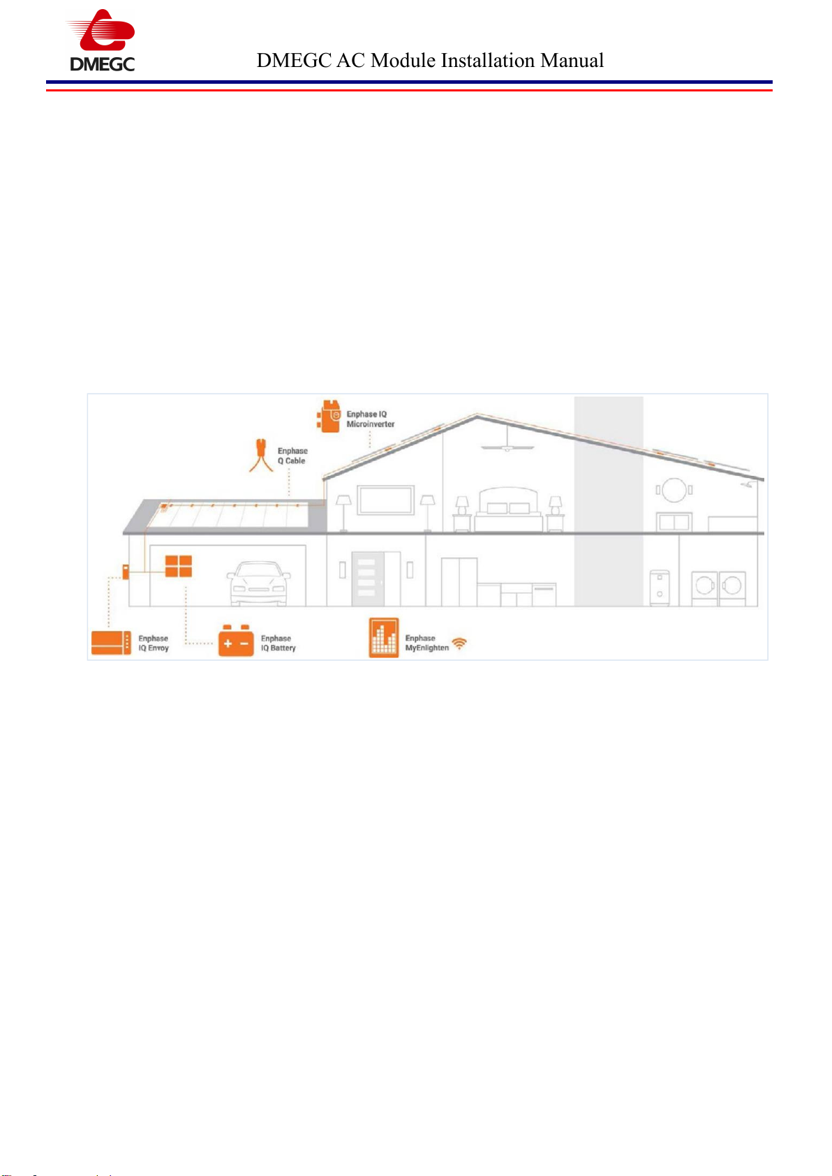
2. The Enphase IQ System
The Enphase IQ System includes:
Enphase IQ Microinverters for DMEGC AC Module, The smart grid ready Micros convert the DC output of
the PV module into grid-compliant AC power.
Enphase Envoy-S (model ENV-S-WM-230 or ENV-S-WB-F/G/I) communications gateway or IQ Combiner
(model X-IQ-AM1-240-2 or 240-3). The Enphase Envoy is a communication device that provides network access
to the PV array. The Envoy collects production and performance data from the Enphase IQ Microinverters over
on-site AC power lines and transmits the data to Enlighten through an Internet or cellular modem connection. The
Envoy is capable of monitoring up to 600 Enphase IQ Microinverters and up to 39 Enphase IQ Batteries. For
details, refer to Enphase Envoy-S Installation and Operations Manual.
Enphase EnlightenTM web-based monitoring and management software. Installers can use Enlighten Manager to
view detailed performance data, manage multiple PV systems, and remotely resolve issues that might impact
system performance. Find out more at enphase.com/enlighten.
Enphase Installer ToolkitTM mobile app for iOS and Android devices. It allows installers to configure the system
while onsite, eliminating the need for a laptop and improving installation efficiency. You can use the app to:
Connect to the Envoy over a wireless network for faster system setup and verification
View and email a summary report that confirms a successful installation
Scan device serial numbers and sync system information with Enlighten monitoring software

DMEGC AC Module Installation Manual
- 6 -
2.1 How the AC Module Works
The Enphase Microinverter maximizes energy production by using a sophisticated Maximum Power Point
Tracking (MPPT) algorithm. Each Enphase Microinverter is individually connected to one PV module in your
array. This configuration enables an individual MPPT to control each PV module, ensuring that maximum
power available from each PV module is exported to the utility grid regardless of the performance of the other
PV modules in the array. While an individual PV module in the array may be affected by shading, soiling,
orientation, or PV module mismatch, each Enphase Microinverter ensures top performance for its associated PV
module.
2.2 System Monitoring
Once you install the Enphase Envoy-S or Enphase IQ Combiner and provide an internet connection through a
broadband router or modem, the Enphase IQ Microinverters automatically begin reporting to Enlighten. Enlighten
presents current and historical system performance trends and informs you of PV system status.
2.3 Optimal Reliability
Microinverter systems are inherently more reliable than traditional inverters. The distributed nature of a
microinverter system ensures that there is no single point of system failure in the PV system. Enphase IQ7 and IQ7+
Microinverters are designed to operate at full power at ambient temperatures as high as 65 ℃(149 F).
2.4 Ease of Design
PV systems using Enphase Microinverters are very simple to design and install. You will not need string
calculations or cumbersome traditional inverters. Low voltage DC wires connect from the PV module directly to the
co-located microinverter, eliminating the risk of personnel exposure to dangerously high DC voltage.

DMEGC AC Module Installation Manual
- 7 -
3. Preparation
A ) Download the Enphase Installer Toolkit mobile app and open it to log in to your Enlighten account. With this app,
you can scan microinverter serial numbers and connect to the Enphase Envoy-S to track system installation progress.
To download, go to enphase.com/toolkit or scan the QR code at right.
B ) Refer to the following table and check PV module electrical compatibility at:
https://enphase.com/en-uk/support/module-compatibility
Name
Model Number
Microinverter
DMEGC AC Module
DM315G1-60HBB-A DM320G1-60HBB-A
DM325G1-60HBB-A DM330G1-60HBB-A
DM300M2-60BB-A
IQ7
DM325G1-60HSW-A DM330G1-60HSW-A
DM335G1-60HSW-A DM340G1-60HSW-A
DM330G1-60HBB-A DM330G1-60HBW-A
IQ7+
C ) In addition to the Enphase Microinverters, PV modules and racking, you will need these Enphase items:
•Enphase Envoy-S (model ENV-S-WM-230 or ENV-S-WB-230-F/G/I) communications gateway
•Enphase Q Relay, single-phase (Q-RELAY-1P-INT) or Enphase Q Relay, multiphase (Q-RELAY-3P-INT).
•Tie wraps or cable clips (ET-CLIP-100)
••Enphase Sealing Caps (Q-SEAL-10): for any unused connectors on the Enphase Q Cable
••Enphase Terminator (Q-TERM-R-10) for single phase or (Q-TERM-3P-10) for multiphase: one needed at the
end of each AC cable segment
••Enphase Disconnect Tool (Q-DISC-10)
••Enphase Q Cable: Single-Phase
Cable model
Connector
spacing*
PV module orientation
Connectors per box
Q-25-10-240
1.3m
Portrait (all)
240
Q-25-17-240
2.0m
Landscape (60and 96-cell)
240
Q-25-20-200
2.3m
Landscape (72-cell)
200
*Allows for 30 cm (12 in.) of cable slack.
ACNERGY
ACN-60FB-300
ACN-120FB-330
ACN-120WOB-330
ACN-120WOB-375

DMEGC AC Module Installation Manual
- 8 -
Three Phase
Cable model
Connector
spacing*
PV module orientation
Connectors per box
Q-25-10-3P-200
1.3m
Portrait (all)
200
Q-25-17-3P-160
2.0m
Landscape (60and 96-cell)
160
Q-25-20-3P-160
2.3m
Landscape (72-cell)
160
D ) Check that you have these other items:
•Racking, AC junction box, homerun
•Tools: screwdrivers, wire cutter, voltmeter, torque wrench, sockets, and wrenches for mounting hardware
E ) Protect your system with lightning and/or surge suppression devices. It is also important to have insurance that
protects against lightning and electrical surges.
F ) Plan your AC branch circuits to meet the following limits for maximum number of microinverters per branch
when protected with a 20-amp over-current protection device (OCPD).
Maximum* number
of DMEGC ACMs per AC
branch circuit
IQ 7 Modules (single-phase)
IQ 7+ Modules (single-phase)
16
13
IQ 7 Modules (single-phase)
IQ 7+ Modules (three-phase)
48
39
* Limits may vary. Refer to local requirements to define the number of modules per branch in your area.
G ) Size the AC wire gauge to account for voltage rise. Select the correct wire size based on the distance from the
beginning of the Enphase Q Cable to the breaker in the load center. Design for a voltage rise total of less than 2% for
these sections. Refer to the Voltage Rise Technical Brief at enphase.com/support for more information.
Best practice: Center-feed the branch circuit to minimize voltage rise in a fully populated branch.
4.Enphase Microinverter Installation
Installing the ACM involves several key steps. Each step listed here is detailed in the following pages.
Step 1: Operating Conditions
Step 2: Unpacking and Handling
Step 3: Prepare the Microinverter
Step 4: Position the Enphase Cable
Step 5: Connect the Microinverter
Step 6: Create an Installation Map
Step 7: Module Installation
Step 8: Manage the Cabling
Step 9: Terminate the Unused End of the Cable
Step 10: Install an AC junction box

DMEGC AC Module Installation Manual
- 9 -
Step 11: Energize the system
Step 12: Wiring General
Step 13: Module Wiring
Step 14: Array Wiring
Step 15: Ground the DMEGC ACMs
Step 16: Set Up and Activate Monitoring
Step 1: Operating Conditions
DMEGC Photovoltaic modules be operated within the following Operating Conditions. An installation location
with conditions outside the Operating Conditions or with other Special Conditions (see below) must be avoided.
The modules should be operated only in terrestrial applications.
The operating module temperature must be within 30℃(-22 F) to 85℃(185 F).
The wind pressure load of the installation site should be less than Load Resistance shown in Mount Locations
and Load Resistance.
Step 2: Unpacking and Handling
Do not hit the back sheet of a module with the connector when unpacking and handling.
Please do not expose the connector to rain water and/or dust .
To avoid damage to the back sheet by the connector, do not cut the string binding the cables of junction box.
Do not handle modules while holding their cables, junction box or microinverter. Handle modules while holding
the frame with both hands in any situation.

DMEGC AC Module Installation Manual
- 10 -
Step 3: Prepare the Microinverter
Before installing the PV module the microinverters must be lifted from the shipping position. On the ground, turn
the PV module so that the microinverter faces you.
Using both hands, lift the microinverter up. You will hear four clicks as the microinverter locks into the
installation position (deployed position). Ensure that the four latches are locked, and the microinverter is not
tilted.
Place the PV modules on the roof. Do not place the PV modules in such a way that places pressure on the
microinverter.
If you need to service, you can return the microinverter to the shipping position using theEnphase Disconnect
Tool. Use the tool to depress the four locking switches on each corner of the microinverter to return it to the
shipping position.(See Figure.4-1)
If the problem persists, contact Customer Support at Website as follows:
https://enphase.com/en-us/company/
Figure 4-1. How to move to the shipping position using the Enphase Disconnect Tool.
Step 4: Position the Enphase Cable
Plan each cable segment to allow the drop connectors on the Enphase Q Cable to align with each PV module.
Allow extra length for slack, cable turns, and any obstructions.
Mark the approximate centers of each PV module on the PV racking.
Lay out the cabling along the installed racking for the AC branch circuit. Make sure that the cable is positioned in
a way that allows you to connect it to the microinverter.
Cut each segment of cable to meet your planned needs.
When transitioning between rows, secure the cable to the rail to prevent cable damage or connector damage. Do
not rely on the connector to withstand tension.
When transitioning, do not damage at cable or connector.

DMEGC AC Module Installation Manual
- 11 -
Step 5: Connect the Microinverter
Connect the Q Cable to the microinverter. Listen for a click as the connectors engage. (See Figure 4-2)
Figure 4-2. Connect the Q Cable to the microinverter
Cover any unused connectors with Enphase Sealing Caps. Listen for a click as the connectors engage.
You must lift the microinverter in order to connect it. A protective shield prevents connection.
Step 6: Connect the Microinverter
Use the Enphase Installer Toolkit mobile app to record the serial numbers and configure the system.
For Enphase Installer Toolkit details, refer to Detecting Microinverters in the help topics of the Installer Toolkit
app.
Step 7: Module Installation
Install modules where they are not shaded by obstacles like buildings or trees. Especially pay attention to avoid
partially shading the modules by objects during the daytime. If a part of the PV module is always shaded, hot
spots may occur, and the PV module may break down.
Water stains can be caused when rainwater remains on the glass surface for a long time. To avoid water stains,
install modules at a slope steeper than the water gradient.
Modules should be firmly fixed in place in a manner suitable to withstand all expected loads, including wind and
snow loads.
Metals used in locations that are exposed to moisture shall not be deployed alone or in combinations that could
result in deterioration or corrosion.
The clamps must be made of aluminum alloy or other material that will reasonably protect against a risk of
electrolytic corrosion.
Clearance between the roof surface and module frame is required to allow cooling air to circulate around the
back of the module. This also allows any condensation or moisture to dissipate. The required clearance between

DMEGC AC Module Installation Manual
- 12 -
the roof surface and the module is more than 100mm (4 inches or more).
Clearance of 7 mm or more between modules is required to allow for thermal expansion of the frames.
Figure 4-6 shows using a bolt and nut for mounting.
Figure 4-3. Mounting with Bolts

DMEGC AC Module Installation Manual
- 13 -
Figure 4-4. Mounting with Clamps
Do not contact allow the bolt to contact the back sheet of the module when securing the module to the mounting
rail.
Do not allow the microinverter to interfere with the mounting structure rail when securing the module to the
mounting rail. (See Figure 4-5)

DMEGC AC Module Installation Manual
- 14 -
Figure 4-8. Position of the mounting structure rail
Please fix the module so that the microinverter is not placed on the mounting structure rail.
Appropriate material should be used for mounting hardware (the module frame, mounting structure, and
hardware) to prevent itself from corrosion.
DMEGC does not provide a warranty for clamps. The module warranty DMEGC provides shall be voided if
clamps selected by the customer are an improper material or size.
Step 8: Manage the Cabling
Use cable clips to attach the cable to the PV module frame. Leave no more than 1.8 m (six feet) between cable
clips.
Dress any excess cabling in loops so that it does not come into contact with the roof. Do not form loops smaller
than 12 cm (4 inches) in diameter.
Tripping Hazard. Loose cables can become a tripping hazard. Dress the Enphase Q Cable to minimize this
potential.

DMEGC AC Module Installation Manual
- 15 -
Step 9: Terminate the Unused End of the Cable
Terminate the unused end of the Enphase Q Cable (See Figure 4-6).
Remove 13 mm ( 0.5 inch) of the cable sheath from the conductors. Use the terminator loop to measure 13 mm.
Slide the hex nut onto the cable. There is a grommet inside of the hex nut that should remain in place.
Insert the cable into the terminator body so that each of the two wires land on opposite sides of the internal
separator.
Insert a screwdriver into the slot on top of the terminator to hold it in place and use a 27 mm wrench or channel
lock pliers to tighten the hex nut to 7 Nm.
Hold the terminator body stationary with the screwdriver and turn only the hex nut to prevent the conductors
from twisting out of the separator.
Turn only the hex nut to prevent conductors from twisting out of the separator.
Attach the terminated cable end to the PV racking with a cable clip or tie wrap so that the cable and terminator do
not touch the roof.
Figure4-6. Terminate the Unused End of the Cable
The terminator cannot be reused. If you unscrew the nut, you must discard the terminator.
Step 10: Install an AC Junction Box
The Enphase Microinverter works with single-phase 230 VAC service.
A)Verify that AC voltage at the site is within range:
Single-Phase
Three-Phase
L1 to N
207 to 253 VAC
L1, L2 to L3
360 to 440 VAC
L1, L2, L3 to N
207 to 253 VAC
B) Install a junction box at a suitable location on the racking.
C) Provide an AC connection from the junction box back to the electricity network connection using equipment
and practices as required by local jurisdictions.

DMEGC AC Module Installation Manual
- 16 -
Refer to the wiring diagrams in Figure 4-7 for more information. Wire colors are listed in the following table.
Wire Colors
L1-Black
L2-Red
Figure 4-7. Sample Wiring Diagram
Step 11: Energize the system
Turn ON the AC disconnect or circuit breaker for the branch circuit.
Turn ON the main utility-grid AC circuit breaker. Your system starts producing power after a five-minute wait
time.
Check the LED on the connector side of the microinverter:
LED color
Indicates
Flashing green
Normal operation. AC grid function is normal there is communication with the
Envoy-S
Flashing orange
The AC grid is normal but there is no communication with the Envoy-S.
Flashing Red
The AC grid is either not present or not within specification.
Solid Red
There is an active DC Resistance Low, Power Off Condition. To reset, refer to DC
Resistance Low Power Off Condition on page23.

DMEGC AC Module Installation Manual
- 17 -
Step 12: Wiring General
All wiring should be done in accordance with applicable electrical codes.
All wiring should be done by a qualified, licensed professional.
Wiring should be protected to help ensure personal safety and to prevent its damage.
Connectors between Microinverters must be inserted until they click.
When connecting the connectors, you must make sure that foreign matter such as water, sand and debris do not
get inside the connector. Also, please keep in mind that if you leave the connector in a nonconnected state for a
long period of time, contamination of foreign matter is likely to occur. This voids the warranty.
If an extreme tension or weight load is applied to the cable, the cables may come off the junction box body or the
connectors. You must connect these so that a strong load is not applied to the cable.
Do not disconnect terminals while modules generate electricity and do not connect electrical load during
disconnection to avoid the hazard of electrical shock.
Cable conduits should be used in locations where the wiring is inaccessible to children or small animals.
Step 13: Module Wiring
All modules with microinverter connected in parallel by Enphase’s Q cable should be of the same model number
and/or type.
Refer to the Enphase IQ 7 Installation and Operation Manual for instructions on Q Cable connection, AC
connector connection, and other connections.
Refer to the Enphase IQ 7 Microinverter Installation Guide for configuration and operation of a Microinverter.
https://enphase.com/sites/default/files/downloads/support/IQ7-IQ7plus-man-INTL-EN-EN.pdf
Step 14: Array Wiring
The term array is used to describe the assembly of several modules on a support structure with associated wiring.
When installing a PV array, the system design must be completed with reference to the module and inverter
electrical specifications for proper selection of fuses, breakers, charging controllers, batteries and other storage
devices. In particular, as the temperature characteristic of the PV module, the voltage value rises on the low
temperature side. Consider the lowest temperature in the area where the system is installed and select the
equipment so that it does not exceed the rated voltage of the equipment.
Use copper wire insulated to withstand the maximum possible system open circuit voltage. For applications
where wire conduits are used, follow the applicable codes for outdoor installation of wires in conduits. Minimum
diameter of wire conduit is 4 mm2. The temperature rating of conductor is 40 ~ 90.
To avoid submerging cables and connectors in the water, cables must be secured either to the module frame using

DMEGC AC Module Installation Manual
- 18 -
cable fixing holes or to the mounting structure. Also, if the cable is not secured, a force may be applied to the
cable from the outside, and the module may be damaged.
Do not insert PV cable between back side and mounting structure rail. Note that when snow or wind load is
applied to the module, increased load may be applied to the cable.
Verify that all fittings are properly installed to protect cables against damage and prevent moisture intrusion.
Check your local codes for requirements.
Step 15: Ground the DMEGC ACMs
Choose to use grounding clamps or module mounting holes to ground the modules. Or, you can use a reliable
third-party grounding system.
All methods:
A. Ground the module frames to protect the array from lightning and static-electricity damage using Method A, B,
or C.
B. Be sure that the grounding device will fully contact the inner side of the aluminum alloy and penetrate the
frame surface oxide film.
C. Make a connection from the grounding conductor to earth using a suitable earth ground electrode.
WARNING: Risk of equipment damage. Do not drill additional grounding holes on module frame.
The module frame has been drilled and marked for grounding. Use the grounding holes only for
grounding, and do not used them for mounting or other purposes.
NOTE: The grounding conductor or strap can be copper, copper alloy, or any other material acceptable
for use as an electrical conductor per the National Electrical Codes. The grounding wire material and
size must meet all local and regional requirements.
Method A: Grounding with grounding clamps.
Locate the grounding hole (diameter Ø4 mm) at the edge of the module frame back.
Use 12 AWG copper core wire for the grounding clamp, and do not damaged the copper wire during installation.
Torque to 2.3 N. m.
This manual suits for next models
3
Table of contents