DMI TURBO-TIGER User manual

Operators Manual
Parts Catalog
Designed and Manufactured with Ingenuity
CNH America LLC
600 E Peoria St.
Box 65
Goodfield, Illinois 61742
00100460
turbo–tiger®

TO THE OPERATOR
DMI has built performance, features, reliability, and long life into this product, but it is your responsibility to operate and
service this machine properly in order to realize these built in benefits.
DMI urges you to read and understand this manual and to instruct all who will operate the implement to proper operation
and service.
When ordering parts, provide the complete model number and serial number of the machine (should be filled in
below), in addition the part number and part description.
MODEL NUMBER ________________________SERIAL NUMBER________________________________
DATE PURCHASED _______________________DEALER PHONE NUMBER _______________________
DEALER NAME__________________________________________________________________________
NOTE: When the term "Right" or "Left" is used, it means from a position behind the implement and facing the front.
BOLT TORQUE
READ THESE INSTRUCTIONS FIRST:
1. Improperly tightened bolts will result in damage, breakage, expense, and downtime.
2. Always replace bolts with the specified grade and type.
3. Torque properly before first use of the machine and every 2-4 hours of use until you are sure bolts are staying tight.
4. The chart below is a guide for proper torque. Use it unless a specified torque is called out elsewhere in the manual.
5. Torque is the force you apply to the wrench handle or the cheater bar, times the length of the handle or bar.
6. Use a torque wrench whenever possible.
The following table shows torque as measured in ft-lbs.
NOTE: Torque values given are for lubricated hardware. Increase values given by 10% non-lubricated hardware. Use
65% of torque value given for jam nuts


10/04 turbo-tiger® – 04 – DMI 1
TABLE OF CONTENTS
TO THE OWNER..............................................................2
SAFETY SUGGESTIONS.................................................3
SPECIFICATIONS............................................................4
FEATURES ................................................................5
ASSEMBLY INSTRUCTIONS ..........................................6
LUBRICATION..................................................................7
ADJUSTING & OPERATING .......................................8, 9
SPRING TRIP ADJUSTMENT........................................10
MAIN FRAME PARTS ............................................ 12 - 16
HYDRAULIC SYSTEM .............................................18, 19
AUTO RESET ASSEMBLY..................................... 20 - 23
SPRING TRIP ASSEMBLY.......................................24, 25
STABILIZER WHEEL............................................26, 27
DISC MOUNT ASSEMBLY ...................................28, 29
DISC HUB ASSEMBLY.........................................30, 31
DISC HUB MOUNT ORDERING ................................32
HYDRAULIC ASSEMBLY ....................................33 - 39
5 BOLT HUB ASSEMBLY.....................................40, 41
778 HUB AND SPINDLE ASSEMBLY ..................42, 43
821 HUB AND SPINDLE ASSEMBLY ..................44, 45
JACK ASSEMBLY................................................46 - 49
DISC FRAME RELIEF VALVE..............................50, 51
LIMITED WARRANTY.................................................52

TO THE OWNER
Your new DMI “Turbo-Tiger” is the most versatile machine you can own. The ease of operation and ability to hydraulically adjust
on the go from the tractor seat, make this a non-stop tillage tool. The Turbo-Tiger will do an excellent job and give years of reliable
service when used according to these simple principles listed below.
SHANKS
SHANK DEPTH IS NOT TO EXCEED 16”. The points on the Turbo-Tiger shanks are designed to work at the plow sole level.
Best results are when the very point is about 2” or just above the plow sole. The winged points will fracture the soil, lift, twist, &
turn this layer without creating a new plow sole. The Turbo-Tiger is not designed to be a deep sub-soiler implement. The fracturing
of the plow sole allows moisture, freezing and thawing action to extend the crop root zone, provides a loosened soil for faster warm
up in the spring and better drainage of spring moisture.
LEVELING MACHINE
THE “A” FRAME OF THE TURBO-TIGER MUST BE LEVEL. The hitch clevis can & must be positioned to provide a level A-
frame. A low front end will surely result in excessive disc depth and “floating out” of the shanks. The disc frame itself must be
level. The distance from level ground to the bottom of the discs must be the same for both front & rear disc rows. The long
turnbuckle provides adjustment. NOTE: WHEN LEVELING THE DISC FRAME DO NOT MEASURE THE REAR, OUTSIDE
BLADES; THEY ARE DESIGNED TO RN 1 INCH LESS DEEP. Performance will suffer and machine damage is certain if the
front discs are higher or lower that the rear discs and the discs are run deep.
DISC BLADES
THE DISC DEPTH MUST NOT EXCEED 5 INCHES. Best performance is in the range of 3 to 4 inches. Excessive disc depth
increases horsepower, fuel consumption, reduces tractor forward speed below the optimum 5-6 MPH, decreases trash mixing &
coverage and leads to excessive wear and tear on equipment. Running the discs over 5” deep causes the shanks to float up. The
winged shank points are not down in the plow sole and not lifting, turning, and breaking up the soil in the plow sole area as the
Turbo-Tiger is designed to do.
The Turbo-Tiger is not designed to till deep and not designed to leave the field “black”. The customer who wants to grind the soil
and trash up finely and run the disc hub deep would be better off with a heavy-duty tandem disc with 32-36 inch disc blades.
The front discs are designed to cut trash, , mix trash with soil, and windrow the mixture, and move the windrow into the path of the
rear discs. The windrow is then re-cut remixed, and moved sideways in the opposite direction to leave the ground level.
A solid 2-1/4” x 2-1/4” solid steel bar attaches each disc hub to the vertical disc post. The 2-1/4” square bar is designed to fail
under extreme loading to prevent damage to the signed to disc frame. BREAKAGE OF THE BARS IS A SURE INDICATION OF
EXCESSIVE DISC DEPTH.
When discs are run over 5” deep, the nut on the top of the long disc spring bolts will be “peened”. This is because the discs are
constantly raising and lowering & slamming the nut against its seat. The constant up & down movement of the disc will also cause
premature wear of the pivot pin mount holes where the disc arm attaches to the disc vertical post. IT IS IMPORTANT TO RAISE
THE DISCS IN HARD PACKED END ROWS AND WHEN TURNING AT FENCE CORNERS.
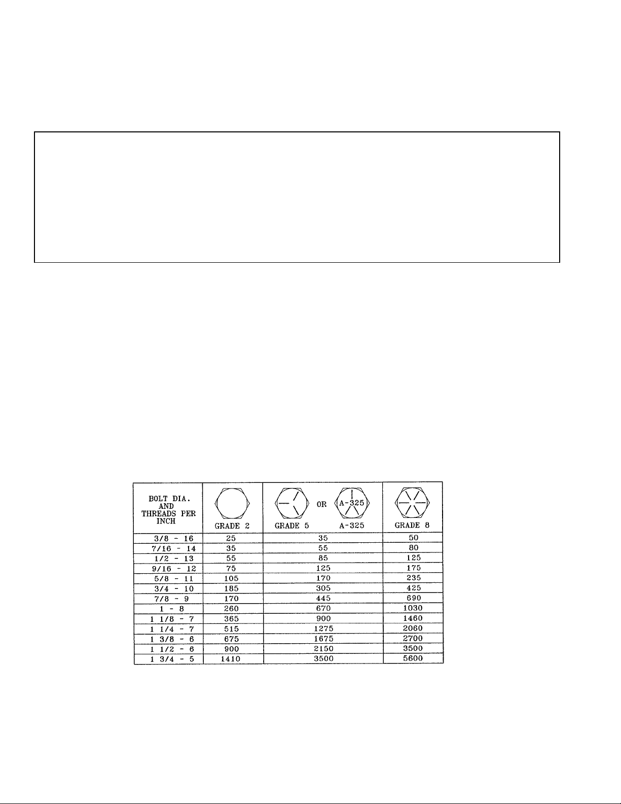
TORQUE
ALL BOLTS ON THE TURBO-TIGER MUST BE FULLY TIGHTENED, AND KEPT TIGHT. This is a massive machine doing
a massive job. Loose bolts mean loose parts and then parts breakage. Below are listed several areas where fully tightened bolts are
of extreme importance because of the expensive damage that can result.
A. The 7/8” dia bolts fastening disc hub to disc mount. Torque to full 450 ft-lbs. Use a 3’ long (minimum) “cheater bar” and
socket with ¾” drive.
B. The 1-3/4” nuts on disc hub spindles. DMI will factory torque these nuts to 1200 ft-lbs. or more.
C. The ¾” dia shear bolt and 7/8” to 450 ft-lbs. – using 3’ long (minimum) “cheater bar” & socket with ¾” drive. Retighten after
a few hundred feet.
2turbo-tiger® – 04 – DMI 10/04

SAFETY SUGGESTIONS
A. Never unhook implement from tractor in transport position
B. When transporting , always insert transportation pin.
C. Always check wheel bolts before roading.
D. Never permit riders on implements or tractors.
E. Proceed slowly on rough or slippery ground of roadways.
F. Reduce speed when approaching ditches and corners
G. When transporting implements, always maintain a safe speed.
H. Tow with farm tractor only.
10/04 turbo-tiger® – 04 – DMI 3

SPECIFICATIONS
5 – Shank 7 – Shank 11.00 x 16
8 – Ply Tire 16.5 x 16.1
8 – Ply Tire
MODELS
Shear Bolt Shank X X X -----
Spring Trip Shank X X ------ X
Auto Reset Shank X X ------- X
WINGS
Main Frame Wing (One Shank) ------- X A – Shear Bolt Model
Disc Frame Wing (One Blade) X -------
Disc Frame Wing (Three Blade) ------- X B – Spring Trip and Automatic
CYLINDERS Reset Model
4 x 16 Main Lift (31-1/2” Closed) A ------
4 x 16 Main Lift (26-5/8” Closed) B ------ C - Optional
5 x 16 Main Lift (31-1/2” Closed) ------ A
5 x 16 Main Lift (28-1/4” Closed) ------ B D – Option for 7 Shank Spring
3 x 8 Disc Frame Lift X --------- Trip and Automatic Reset
3-1/2 x 8 Disc Frame Lift -------- X Models. Not Available for
3-1/2 x 24 Disc Wing Lift C X Shear Bold Model
4 x 24 Main Frame Wing Lift --------- D
24 Inch Disc Blades 12 16
4turbo-tiger® – 04 – DMI 10/04

FEATURES
1. Discs cut the trash and effectively mix it (and surface applied fertilizer) into the top few inches of soil.
2. Portions of the trash cut by the front row of discs are thrown in front of the rear row of discs, where it is recut.
3. The discs are spring loaded to ride over rocks and other obstacles, with a minimum of damage to the blades.
4. The discs are mounted on a separate frame so the tillage depth can be set independently of the chisel shank depth.
5. The tillage depth of the discs can be adjusted “on the go” from the tractor cab.
6. The cutting angle of the discs can be adjusted to vary the amount of trash coverage.
7. The points on the Turbo-Tiger shanks are designed to work at the plow sole level. Best results are when the very point is about
2” below the plow sole and the wings of the point working at or just above the plow sole. The winged point will fracture the
soil, lift, twist, & turn this layer without creating a new plow sole. The Turbo-Tiger is not designed to be a deep sub-soiler
implement. The fracturing of the plow sole allow moisture, freezing and thawing action to extend the crop root zone, provides
a loosened soil for faster warm up in the spring and better drainage of spring moisture.
8. New winged points on the chisel shanks shatter and open nearly all of the soil between the shanks. The points with wings on
30” centers are as effective in opening up the soil as conventional points on 20” centers.
9. Automatic Reset linkage provides the maximum load on the chisel point when it is in the working or home position. The load
on the point quickly drops when the shank is moved from the home position, to allow the point to ride up and over the
obstruction.
10. The automatic reset and the spring trip shank is further protected by a shear bolt (as is the rigid shank) for protection against
catching unusual obstructions.
10/04 turbo-tiger® – 04 – DMI 5

ASSEMBLY INSTRUCTIONS
Assemble the Turbo-Tiger in the following order. Refer to the exploded parts drawings and reference number on pages 12-16.
1. Attach the Pull Frame to the Main Frame with six – ¾ grade 5 bolts, ¾” flat washers, lock washers and nuts. IMPORTANT:
These bolts must be torqued to 350 ft-lbs. using a three-foot cheater bar.
2. Attach the cylinder mount to the main frame. On rigid shank machines attach clamp assembly to cylinder mount and pull
frame.
3. ON RIGID SHANK MACHINES, bolt down the inner tube clamps, with triangular gusset towards the rear. Install the proper
number of shims under the clamps, so there is clearance between the tube and the pads on the main frame when the tube is
forced up to the top of the clamp.
4. Connect the lift links between the lift tube and the spindle arms.
5. Mount the two tires and wheels.
6. To install the disc frame on the pull frame, you must remove the two disc hubs on the front row that are directly under the pull
frame. Then, install disc frame on pull frame by pinning the lift tube arms to the front tube of the disc frame. Position hubs so
that dimensions “D” (Fig #4, page 9 is the same on all assemblies). IMPORTANT – Torque 7/8” diameter, Gd. 5 bolts to 400-
450 ft-lbs. using a ¾” drive socket and a four-foot cheater bar.
7. Attach the disc frame lift tube to the pull frame with four ¾” x 2-1/2” bolts and ¾” nuts.
8. Set turnbuckle at 50” and install.
9. Connect the main lift cylinder and hoses to the lift tube on the main frame. (IMPORTANT: Lift cylinder hoses MUST be
allowed to loosely hang over disc frame. See Fig #2). Install the disc frame lift cylinder & hoses to pull frame & disc frame lift
tube. If included on your machine, install the 3-1/2” x 24 wing lift cylinders and hoses.
10. On rigid shank machines attach the shank assemblies on 30 inch spacing, using one ¾” diameter special bolt and a 7/8”
diameter A-325 bolt. Install a 7/8” machinery bushing between shank and mounting angles, as required, to remove all side
play. IMPORTANT: - The ¾” diameter special shear bolt and 7/8” diameter pivot bolt, must be torqued to specifications.
Torque the ¾” bolt to 250 ft-lbs. by using a three foot long (minimum) cheater bar and a ¾” drive socket. Retighten after a
few hundred feet of operation.
11. For spring trip and automatic reset shanks, see pages 20-25. Install beam assembly on to main frame by inserting a 2-inch
diameter pivot bolt through the beam assembly. Install a 1-inch diameter pivot bolt through linkage arm, for trip or automatic
reset mechanism.
NOTE: Shank shear bolt is made of a specific material especially designed for shear bolt applications. It is mandatory that the
shank shear bolts always be replaced with these special bolts. If a grade 5, ASTM A-325, or grade 8 is substituted, then structural
failure may result to this machine.
6turbo-tiger® – 04 – DMI 10/04

10/04 turbo-tiger® – 04 – DMI 7

ADJUSTING & OPERATING
Once the Turbo-Tiger shanks are at the desired depth, as described on page 2, the machine must be leveled. A low front end will
cause excessive disc depth and possible structural damage. With the shanks in the soil, measure distance “A” and “B” (Fig #2) from
level ground to the arrow on the decals – THIS DISTANCE MUST BE THE SAME. Once this distance is obtained, step back
approximately 50 feet and view the machine. The Turbo-Tiger should appear level to the ground, if not, make certain the ground is
level under the decals. The Turbo-Tiger can be leveled by changing the position of the hitch clevis, which has an adjustment range
of 13-1/2” (Fig #3).
8turbo-tiger® – 04 – DMI 10/04

ADJUSTING & OPERATING (CONT.)
Once the depth of the shanks are set and the Turbo-Tiger is level, the depth of the disc frame may be adjusted. The disc blades
should be set to where the blades run 2 to 4 inches deep – NEVER MORE THAN 5 INCHES DEEP. When leveling the disc frame
(refer to Fig #2 on page 8). Measure from the top of the “A” frame to the underside of the 4 x 4 tube on the disc frame, front and
rear. By design, the distance of the front tube should be ½ inch greater than the rear tube (dimension “C”). To adjust rotate the 50-
inch long turnbuckle. NOTE: If nut #123 on bolts #113 and #114 are “peening”, the disc blades are running to deep.
The Turbo-Tiger is not designed to till deep and not designed to leave the field “black”. For best results in trash coverage, it is
recommended that the machine be run 20º to 25º diagonally to the rows. If additional trash coverage is desired, a light disking may
be done before using the Turbo-Tiger.
When operating the Turbo-Tiger, if the machine pulls to the left or right, the individual disc blades may be adjusted to make the
machine pull straight. (Refer to Fig. #1 on page 7 & Fig. #4 on page 9). For example, if the machine pulls to the left, then increase
the angle of the disc blades on the left front of the disc frame (in other words, decrease dimension “D” in Fig. #4). NOTE: The
outer left rear and right rear disc blades should be set a the smallest angle possible, (increase dimension “D”) to avoid leaving a
furrow.
A solid 2-1/4” x 2-1/4” solid steel bar attaches each disc hub to the vertical disc post. The 2-1/4” square bar is designed to fail
under extreme loading to prevent damage to disc frame. BREAKAGE OF THE BARS IS SURE INDICATION OF EXCESSIVE
DISC DEPTH.
The Turbo-Tiger works best when operated at the fairly high speed, from 5 to 6 mph. Therefore, a minimum tractor size of
approximately 175-drawbar hp is required for a 5-shank machine.
10/04 turbo-tiger® – 04 – DMI 9

SPRING TRIP ADJUSTMENT
SHANK TRIPS TOO EASY
1. Raise the shank up into tripped position and secure linkage. Do this by slightly pulling trip spring down away from roller and
prying top links upward.
2. Scribe a line on the trip spring along the edge of the top flat.
3. Loosen the two 3/8” x 1-3/4” cap screws and slide the spring forward 1/16” and retighten.
4. Release shank and inspect the trip spring to insure roller contacts spring at point “A”. If adjustment is required, loosen the two
7/8” x 2-1/4” cap screws and pivot trip spring mount.
5. Repeat on remaining shanks if necessary.
SHANK TRIP TO HARD
1. Raise the shank up into tripped position and secure linkage. Do this by slightly pulling trip spring down away from roller and
prying top links upward.
2. Scribe a line on the trip spring along the edge of the top flat.
3. Loosen the two 3/8’ x 1-3/4” cap screws and slide the spring to the rear 1/16” and retighten.
4. Release shank and inspect the trip spring to insure roller contacts spring at point “A”. If adjustment is required, loosen the two
7/8” x 2-1/4” cap screws and pivot trip spring mount.
5. Repeat on remaining shanks if necessary.
NOTE: Shank trips too hard if the shank bolt shears, or rocks are being lifted to the surface.
TO RESET SHANK
To reset the shank, stop the tractor and raise the Turbo-Tiger out of the ground. If the shank does not reset, then there is excessive
pressure at point “A” or the 1 x 3-3/4” pivot bolts are too tight.
10 turbo-tiger® – 04 – DMI 10/04

10/04 turbo-tiger® – 04 – DMI 11
Parts Section

12 turbo-tiger® – 04 – DMI 10/04

10/04 turbo-tiger® – 04 – DMI 13

14 turbo-tiger® – 04 – DMI 10/04
MAIN FRAME ASSEMBLY
REF NO PART NO QTY NO DESCRIPTION
1 09946100** 1 RH Wing
09947100** 1 LH Wing
2 09940100 1 Main Frame (SB Model)
09931100 1 Main Frame (SB Model)
09801100 1 Main Frame
09858100 1 Auto Reset Main Frame
3 09902100 1 Pull Frame (SB Model)
09937110 1 Pull Frame (A/R & S/T Model)
4 09903100 1 Disc Frame
5 09806000 1 Main Lift Tube (S/B Model)
09926000 1 Main Lift Tube (A/R & S/T Models)
09803000 1 Lift Tube
09902300 1 Rear Pivot Tube
6 09902500 1 Disc Frame Point Bundle
7 09907000 5 10" Standard Point
8 09945000 5 Shank Assy W/Point (A/R & S/T Model)
09910000 5 Shank Assy W/Wing Point
9 09942000 6 Hub Assy W/Disc LH/RH
10 09905100 1 Center Disc Mount
11 09905300 5 Left Disc Mount
12 09905200 5 Right Disc Mount
13 32230000 1 Jack Assy
14 14892047 1 Pin
15 14892046 10 Pin
16 32408000 1 Turnbuckle W/Pins
17 09911000 1 RH Dirt Shield
09912000 1 LH Dirt Shield
18 09923000 1 Cylinder Mount (A/R & S/T Model)
19 09908000 1 Single Disc RH Wing (Shown)
09908100 1 Single Disc Weld RH
09913000 1 Single Disc RH Wing Assy
09909000 1 Single Disc LH Wing
09909100 1 Single Disc Weld LH
09914000 1 Single Disc LH Wing Assy
09919000** 1 Three Disc RH Wing
09919100** 1 Three Disc RH Wing Weld
09900023** 1 Three Disc RH Wing Assy
09920000** 1 Three Disc LH Wing
09920100** 1 Three Disc LH Wing Weld
09900024** 1 Three Disc LH Wing Assy
20 09835001** 1 RH Spindle Arm (SB Model)
09835000** 1 RH Spindle Arm Weld
09804000 1 RH Spindle Arm (SB Model)
09938000 1 RH Spindle Arm (A/R & S/T Model)
21 09834001** 1 LH Spindle Arm (S/B Model)
09834000** 1 LH Spindle Arm Weld
09805000 1 LH Spindle Arm (S/B Model)
09939000 1 LH Spindle Arm (A/R & S/T Model)
22 09838000** 1 RH Spindle Arm L/Hub (SB Model)
09840000 1 RH Spindle Arm L/Hub (SB Model)
09951000 1 RH Spindle Arm L/Hub (A/R & S/T Model)
23 09839000** 1 LH Spindle Arm L/Hub (SB Model)
09841000 1 LH Spindle Arm L/Hub (SB Model)
09952000 1 LH Spindle Arm L/Hub (A/R & ST Model)
24 28082100 2 Q-821 Hub Assy
28177800 2 Q-778 Hub Assy

10/04 turbo-tiger® – 04 – DMI 15
MAIN FRAME ASSEMBLY
REF NO PART NO QTY NO DESCRIPTION
25 09817000 2 Lift Link Assy (S/B Model)
09924000 2 Lift Link Assy (A/R & S/T Model)
26 09820010** 2 Hinge Pin Assy
27 10010162 2 11.00 x 16 Tire & Wheel Assy
10111166 2 11 x 16.1 8-Hole Wheel
28 10110166 2 10 x 16 8-Hole Wheel
10111166 2 11 x 16.1 8-Hole Wheel
29 NSI 2 11.00 x 16 8-Ply Tire (11011162)
NSI 2 16.5 X 16.1 8-Ply Tire (11016170)
30 09308000 2 Pin
31 09503000 2 Outer Tube Clamp
32 09504000 2 Inner Tube Clamp
33 09936000 5 1-1/2" Shank (SB Model)
09930000 5 1-1/2" Shank (A/R & S/T Model)
09809000 5 Shank
34 09803000 1 Cylinder Mount (SB Model)
35 20092071 1 Single Clevis
36 09900019** 1 RH Hinged Wing W/Hardware
09900020** 1 LH Hinged Wing W/Hardware
37 09917000** 1 RH Hinged Wing
09918000** 1 LH Hinged Wing
38 09503020 8 Shim - 12 Ga.
39 09503021 8 Shim - 14 Ga.
40 24156202 12 Compression Spring
41 20090050 12 Spring Holder Casting
42 20090060 12 Spring Holder Casting
43 09916000 5 Wear Strip w/hardware
44 09916100 5 Wear Strip
45 09907000 5 10" Tiger Point
46 32407020 1 RH Threaded End
47 32407030 1 LH Threaded End
48 32408020 1 Tube
49 14820315 4 Pin
50 14816685 4 Pivot Pin
51 02613000** 2 Collar
52 14820755** 2 Pin
53 14816180 4 1" x 2-7/32" Pin
54 14816395 1 1" x 4-7/8" Pin
55 09922100 1 Cylinder Clamp
56 09922120 1 Plate
57 09524000 1 Wear Washer
58 09922000 1 Clamp Assy
59 14893299** 2 Pin
101 413-744 5 7/16" x 2-3/4" NC Cap Screw Gd 5
102 NSI 2 1/2" x 2" NC Cap Screw (16008080)
103 16008104 2 1/2" x 2-1/2" NC Cap Screw Gd 5
104 NSI 5 1/2" x 3" NC Cap Screw (413-848)
105 16008134 2 1/2" x 3-1/4" NC Cap Screw Gd 5
106 16008144 2 1/2" x 3-1/2" NC Cap Screw Gd 5
107 NSI 11 5/8" x 1-1/2" NC Set Screw (16810064)
108 13-1232 8 3/4" x 2" NC Cap Screw Gd 5
109 16012104 14 3/4" x 2-1/2" NC Cap Screw Gd 5
110 16901216 5 3/4" x 3-3/4" Sp. Bolt
111 16012194 5 3/4" x 4-3/4" NC Cap Screw Gd 5
112 413-12120 1 3/4" x 7-1/2" NC Hex Bolt Gd 5
113 16901269 10 3/4" x 17-3/4" NC Hex Bolt

16 turbo-tiger® – 04 – DMI 10/04
MAIN FRAME ASSEMBLY (CONT.)
REF NO PART NO QTY NO DESCRIPTION
114 16901270 2 3/4" x 22" NC Hex Bolt
115 413-1440 14 7/8" x 2-1/2" NC Cap Screw Gd 5
116 413-1448 6 7/8" x 3" NC Cap Screw Gd 5
117 16901419 5 7/8" x 4-1/4" Sp. Bolt
118 16902027 1 1-1/4" x 6-1/2" Sp. Bolt
119 16902416 5 1-1/2" x 4" Sp. Bolt
120 NSI 5 7/16" NC Hex Nut (14000700)
121 NSI 13 1/2" NC Hex Nut (25-108)
122 NSI 11 5/8" NC Jam Nut (425-1410)
123 NSI 52 3/4" NC Hex Nut (425-1012)
124 NSI 21 7/8" NC Hex Nut (25-1410)
125 14021401 4 7/8" NC Heavy Nut
126 NSI 1 1-1/4" NC Slotted Nut (25-1220)
127 NSI 1 1-1/4" NC Jam Nut (25-1420)
128 NSI 5 1-1/2" NC Jam Nut (25-1424)
129 NSI 10 7/16" Std Flat Washer (17007000)
130 NSI 10 1/2" Std Flat Washer (495-21056)
131 NSI 18 3/4" Std Flat Washer (95-21081)
132 NSI 10 3/4" Lock Washer (492-11075)
133 17913000 12 Square Bevel Washer
134 17414011 16 7/8" Heavy Washer
135 17614012 5 7/8" Mach Bushing
136 17620020 22 1-1/4" Mach Bushing 14 Ga.
137 17620030 22 1-1/4" Mach Bushing 10 Ga.
138 17632010 4 2" Mach Bushing 18 Ga.
139 17632020 4 2" Mach Bushing 10 Ga.
140 17632030 4 2" Mach Bushing 16 Ga.
141 NSI 21 1/8" NPT Zerk (219-86)
142 NSI 5 1/4" -28 Zerk (219-87)
143 NSI 8 1/4" - 1-1/2" Cotter Pin (432-1624)
144 NSI 4 1/4" x 2" Cotter Pin (432-1632)
145 NSI 1 3/16" x 2-1/2" Cotter Pin (14700603)
146 NSI 1 3/16" x 3" Hair Pin (1978738C1)
* - ALL QUANTITIES ARE 5 SHANK MACHINE UNLESS NOTED
** - USED ON 7-SHANK MACHINES ONLY
A/R - AUTOMATIC RESET MODEL
S/T - SPRING TRIP MODEL
NSI - NOT A SERVICE ITEM
BOLD HIGHLIGHTED - NOT AVAILABLE

10/04 turbo-tiger® – 04 – DMI 17
THIS PAGE LEFT BLANK INTENTIONALLY
Table of contents