Messersi TC50 User manual

USE – MAINTENANCE
03672833
MINI
TRANSPORTER
TC50 TC50/AV
No
.
______________

2
CONTENTS
1. GENERAL ACCIDENT PREVENTION ...................................................... 3
2. MAIN CHARACTERISTICS ...................................................................... 5
2.1 MACHINE ID ........................................................................................ 5
2.2 MAIN PARTS OF THE MACHINE ........................................................ 6
2.3 CHARACTERISTICS - TECHNICAL DATA ......................................... 7
3. SAFETY - OPERATING STANDARDS ................................................... 10
3.1 SAFETY LABELS AND STICKERS ................................................... 10
3.2 GENERAL STANDARDS FOR SAFETY AND USE ........................... 11
3.3 LIFTING AND TRANSPORTING ........................................................ 15
3.4 HOISTING AND TRANSPORT ........................................................... 17
4. DRIVING - CONTROL POSITION ........................................................... 18
4.1 MACHINE CONTROLS ...................................................................... 18
4.2 DRIVING ............................................................................................ 19
4.3 SERVICES ......................................................................................... 21
4.4 STARTING UP AND STOPPING THE ENGINE .................................. 23
5. GENERAL MAINTENANCE .................................................................... 25
5.1 GREASE POINTS .............................................................................. 25
5.2 CHECKS AND CONTROLS ............................................................... 26
5.3 TIGHTENING THE TRACKS .............................................................. 27
5.4 REPLACING THE DISCHARGE HYDRAULIC OIL FILTER ............... 30
5.5 LUBRICANT TABLE .......................................................................... 30
5.6 EXPLOSION ENGINE ........................................................................ 31
5.7 MAINTENANCE SUMMARY TABLE ................................................. 31
6. HYDRAULIC TRANSMISSION SYSTEM AND SERVICES .................... 32
7. TROUBLESHOOTING: CAUSES AND REMEDIES ............................... 35
8. NOTES ON MAINTENANCE ................................................................... 37
WARNING!!!
THIS MANUAL MUST ALWAYS FOLLOW THE MACHINE. IT MUST BE
KEPT ON HAND FOR THE OPERATOR'S USE.
BESIDES INSTRUCTIONS ON CORRECT USE OF THE MACHINE, THIS
MANUAL WARNS OF THE RISKS DERIVED FROM INCORRECT USE OF
THE MACHINE.
TO BE KEPT FOR FUTURE REFERENCE.
Revision 03 03/09/2020

3
1. GENERAL ACCIDENT PREVENTION
For the machine to function properly, it must be set-up correctly (installation and use) and
the oil level for the various mechanisms must be checked. Inadequate controls or errors in
installation and use can compromise machine efficiency and jeopardize operator safety.
All information and illustrations contained in this manual refer to the model in production at
the time of publication.
For further information, contact an Authorized Service Center.
The Manufacturer reserves the right to make modifications without prior notification.
Everything contained in this manual is the work of the manufacturer and no part or
illustration herein can be used for other purposes without prior authorization
Prudence is the best defense in preventing accidents and injuries.
Before starting up the machine, carefully read all the instructions contained in this manual.
If you have any doubts, contact the Manufacturer.
Before starting up the engine, make certain that there are no people near the machine, in
particular children.
Never transport or lift anyone except the operator.
Never operate the machine unless you are in good physical condition: never drink
alcoholic beverages while working.
This machine is not approved for roadway driving.
Never use the machine on steep slopes. Use it only on terrain where the slope is less than
the limits indicated below.
Never leave the machine with the Diesel engine running. Always shut down the engine.
Never let minors run the machine.
Never use the machine in confined, poorly aerated spaces: the exhaust gases are
poisonous and could seriously injure the body or even lead to death.
The engine must always be off when refueling. Always keep away from open flames. Do
not smoke.
When performing maintenance, never throw hydraulic oil or lubricant and other liquids on
the ground. Always collect and dispose of them through an Authorized Company.
Never let any unauthorized persons operate the machine. The person assigned to the
machine is responsible for any damage or harm incurred by third parties.

4
Never remove the installed safety devices.
Never park the machine in a place with unstable ground which could give way, particularly
when it is full.
Never operate the machine with inappropriate clothing (garments stained with oil, torn,
etc.).
The manual and some parts of the machine bear the following symbols to indicate safety
messages. To make the reading of this manual easer, follow the indications below:
DANGER !
Whenever this symbol appears, there is significant danger or risk for the safety
of the operator or other persons, and even the risk of death. Apply all
precautions and safeguards suggested in this manual.
WARNING !
This symbol indicates the presence of a potential danger that can be eliminated
by using and following the indications reported in this manual or by using good
sense.
OPERATOR CORRECTLY POSITIONED IN THE DRIVING POSITION

5
2. MAIN CHARACTERISTICS
2.1 MACHINE ID
The machine is equipped with a special label bearing the information that identifies
the unit. This label is riveted to the control casing on the handlebar (operator side).
For any requests, always indicate the type and machine number reported on this
label.
For further clarification, consult the modalities indicated in the Spare Parts Manual
attached with the machine.
All accessories that can be installed on the machine must have their own label. In general,
this label is visible on the outside of the accessory. For further information, see the
documentation for the specific item.

6
2.2 MAIN PARTS OF THE MACHINE
1 - CONTROL PANEL
2 - ENGINE
3 - MOBILE FOOTBOARD (OPTIONAL)
4 - ENGINE HOOD (OPTIONAL)
5 - SCREW TRACK TIGHTENER
6 - DUMP BODY OR LOAD BUCKET
7 - HATCH TO OPEN-CLOSE DUMP BODY OR BUCKET
8 - MACHINE LIFT HOOKS
9 - TRACK
1
2
4
5
6 8
3
9
7

7
2.3 CHARACTERISTICS - TECHNICAL DATA
CHARACTERISTICS
The machine has been designed and built for transporting and dumping of soil, sand,
excavation debris and other loose materials suitable in terms of the characteristics and
performance indicated in this manual.
TC50
TC50/AV
This machine has a manual hydraulic transmission; each lever independently controls the
movement of each track, thus guaranteeing maximum control in all operating situations.
Endothermic explosion engine, air cooled. Manual self-winding pull starter.

8
TECHNICAL DATA
TC50 TC50/AV
Operating weight (without operator) Kg 360 470
Operating load Kg 400
Loading capacity: - piled full (SAE standard) m3 0.310 0.205
- level: sand/liquids m3 0.270 0.175
Engine tipo HONDA GX160
Max RPM rpm 3600
Max. power at 3600 rpm HP/Kw
5.5/4.0
Displacement cm³ 163
Cylinders n° 1
Max. torque at 2500 rpm daNm
1.08
Cooling type Air
Transmission type Hydraulic
Transmission gear pumps n° 3
Total flow rate l/min.
25
Service gear pump n° 1
Flow rate l/min.
14
Max. operating pressure for translation bar 190
Max. operating pressure for services bar 135
Max speed Km/h 1.8/3.9
Independent track steering system type Hydraulic
Track tightening type Adjusting screw
Track width mm 180
Specific ground pressure: - empty / loaded Kg/cm2
0.118/0.254 0.151/0.240
Max gradient capability max %
30
REFUELLING
Fuel tank capacity lt 3,6
Hydraulic oil tank capacity lt 19
Noise emission level at 3600 rpm dBA 101

9
Implementation of EEC Directive 14/2000 regarding limiting noise produced by operating
machinery.
Guaranteed noise level: LWA = 101 dB
Acoustic pressure at operator's ear: LPA = 80 dB
Implementation of EEC Directive 44/2002 regarding minimum safety and health
prescriptions for on-the-job exposure to the risks derived from mechanical vibrations.
Daily action values
Hand-arm system: lower than 2.5 m/sec2
Full body system: lower than 0.5 m/sec2

10
3. SAFETY - OPERATING STANDARDS
3.1 SAFETY LABELS AND STICKERS
Besides indicating the various operations to control and use the machine, the labels also
highlight the risks related to operating the machine.
Operators who normally wear eyeglasses must wear them to read the labels.
Keep the labels clean and legible paying particular attention to the safety indications.
Replace the labels when damaged or missing. The Manufacturer is at your disposal when
you make such request.

11
3.2 GENERAL STANDARDS FOR SAFETY AND USE
The present manual contains the information required to run the machine.
Contact the Manufacturer for any spare parts, accessories or information you might
require.
The tracked minitransporter fit with bucket or open dump body serves to carry and
dump materials.
The materials being handled must comply with the characteristics of the equipment
currently being used.
Avoid abrupt movements. All movements and maneuvers must be performed with
utmost care and while running at a slow speed.
Check that the work area is free and that there are no unauthorized persons
around. Also check that no one enters or passes within the machine operating
range.
In case of operating anomalies while moving the various mobile parts of the machine, turn
the engine off immediately.
Never perform any checks, controls or maintenance operations with the engine
running.
Never transport or lift anyone except the operator.
The operator can only be transported on the footboard only when running on a flat
surface which is paved or smooth and with a load in the bucket of at least 100 Kg.
When hoisting and transporting the machine, follow the instructions given in the
specific chapter.
Before starting up the machine, make certain that the load has been positioned
correctly in the dump body.
When moving over a slope, whether moving forward or in reverse, always make
certain that the weight is evenly balanced.
Never move over terrain that has both a lateral and longitudinal slope.
The terrain must always be solid and compact.

12
GOING UP OR DOWN, WITH LOAD
GOING UP OR DOWN, EMPTY
TRAVELING OVER A FLAT SURFACE, EMPTY
GOING UP OR DOWN, EMPTY AND WITH LOAD
MAX 18 %
30% MAX
30% MAX
30% MAX 30% MAX

13
USE OF THE OPERATOR FOOTBOARD:
The FOOTBOARD must be LIFTED (max height) while the OPERATOR is on the
GROUND.
The FOOTBOARD must be LOWERED with the OPERATOR ON IT.
Never walk behind the unit while the footboard is lowered.
Whether the machine is running or off, to park the machine with full load on a
slope of more than 10%, insert a safety wedge at the tracks. The loaded
machine tends to descend on its own, whether the engine is on or off.
WARNING !
WHEN STOPPING OR PARKING, ALWAYS TURN OFF
THE DIESEL ENGINE
Never use the machine at the rated maximum for excessively long periods of time. Always
alternate with periods operating at more moderate rates. In particular, to prevent damage
from overheating of the hydraulic parts, never make excessively long transfers.
> 10 %
WEDGE

14
Prevent foreign bodies (gravel, stones, debris, etc.) from wedging between the rubber
tracks as this would create interference between the various transmission bodies and
could damage or break them.
HAZARDOUS ZONES !
Because of its operating characteristics, the machine has some pinch points
(lowering the dump body onto the frame, bucket, tracks) and shearing points (dump
body hatch). Particular attention must be taken in using these movements. Never
place limbs or parts of the body in these areas.
If maintenance needs to be performed,
the lift body must be blocked with
special safety elements “S”, supplied
with the machine. They must be inserted
on the lift cylinder shaft. Always lock
with safety pin and plug.
Before parking the machine, set the
bucket on the ground and the body on
the frame to prevent the danger of
pinching or shearing.
In case of machines fitted with Hi-Tip
skip, to block the lifting scissor in upper
position, pull the elastic plug away from
the safety pin “S” and insert it into the
appropriate hole (ref.B). Always insert
the elastic plug. This enables to block
the body lifting chassis to make the
operation/work on the machine in total
safety.
S
S B

15
3.3 LIFTING AND TRANSPORTING
See section 2.3 of this manual for the “overall dimensions of the machine”, while for the
loading on a lorry by using ramps, follow what explained below.
Close the loading/unloading areas, forbidding the entrance to foreign people and
clearing the zone from obstacles and dangerous stuffs.
Loading and unloading operations have to be done in a flat and compact surface.
Check that the transport vehicle is in perfect condition. Apply the hand brake and
insert safety wedges at the front and rear of the rear axle tyres. The vehicle engine
must be off and the key removed from the ignition. The body must be level.
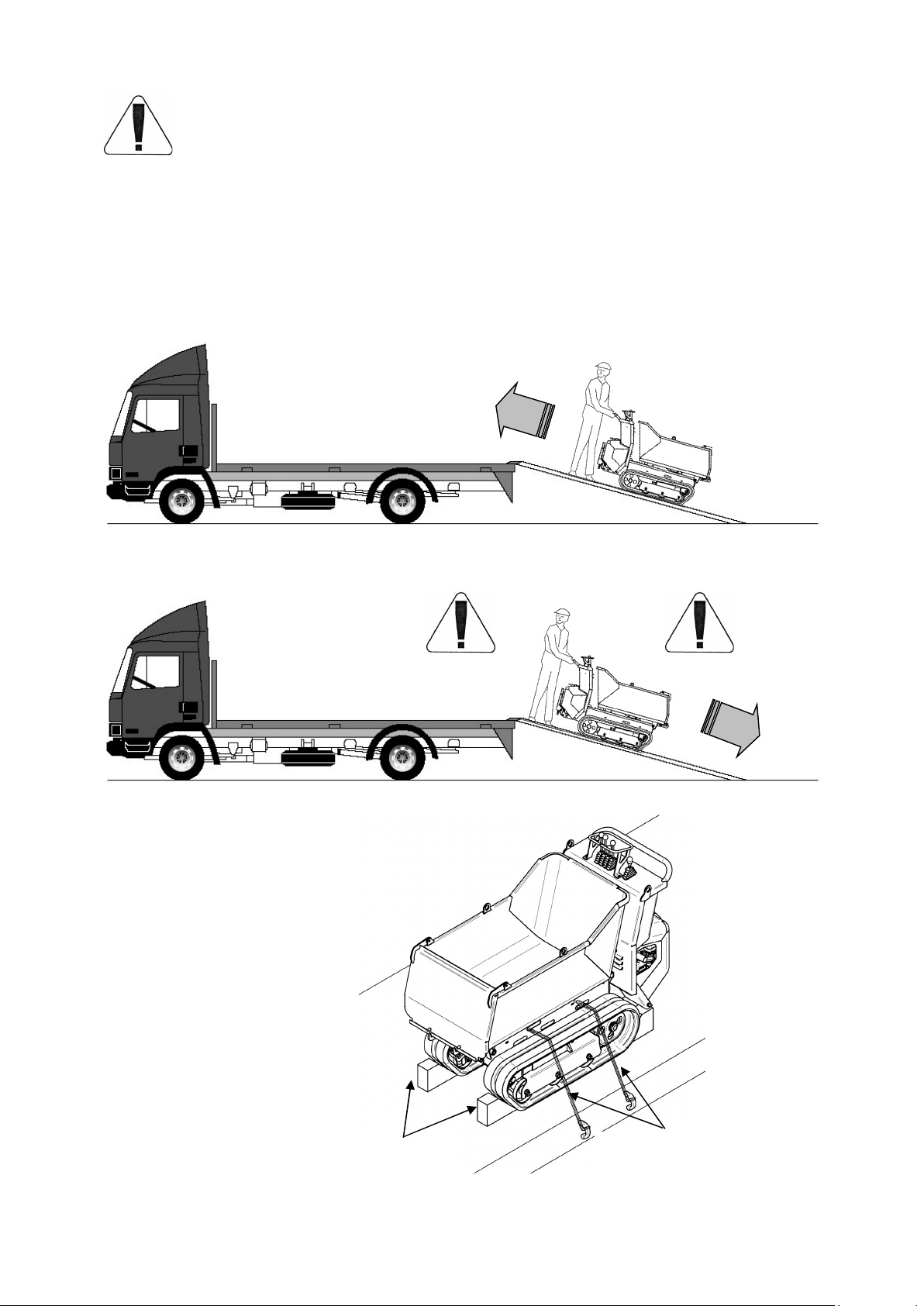
Position the machine at the rear of the truck, ensuring that the longitudinal axle
coincides with that of the truck.
Check that the ramps are suitable for the vehicle to be loaded. Only use
homologated and/or certified ramps.
Check that the ramps are perfectly clean and free of grease and that there is no risk
whatsoever of the tracks slipping.
Check that the ramps are long enough to avoid problems during ascent and
descent of the machine. Particularly check the length of the ramps, taking note their
angle with the lorry loading platform has to be between 15° and 16° (30%).
Check that the ramps are properly coupled to the transport vehicle and
appropriately spaced. The width of the ramp must be such as to allow comfortable
passage of the track.
The ascent and descent operations must always be carried out with the machine
running and the hydraulic oil at operating temperature.
Do not use the ramps as a gangway for crossing from one vehicle to the next.
Load and unload the machine in correct driving ways, as explained below.
Before ascending or descending, check perfect alignment between the tracks and
the ramps. Do not steer or adjust direction while on the ramps. If necessary, return
to the point of departure, repositioning correctly.
Caution with pivoting in the connection area between the ramps and the loading
platform of the truck; the steep slope must be negotiated by moving very slowly and
with extreme caution. Be twice as careful in the descent phase since the unbalance
towards the bottom in this case is much higher.
All the loading and unloading operations of the machine must be carried out and co-
ordinated by at least a second person who controls good progress of the
operations.

16
ATTENTION!!!
It is recommended to close the fuel valve every time the vehicle is transported or handled
in order to prevent causing harm or damage.
To load and unload the transporter from the truck, it is suggested to act as shown below.
Particular attention has to be taken during the overcome of the connection between the
ramps and the lorry loading platform, which can cause an excessive gradient.
ASCENT
DESCENT
TRANSPORT
ROPES WEDGES

17
3.4 HOISTING AND TRANSPORT
The machine must be lifted only when empty
and carefully following the indications below:
- There are four lift connections, two on the front of
the bucket and two on the sides of the driver's station.
(see figure).
- Fence off the lift area to prevent people from
accessing the zone: do not lift over people or things
and make certain that the area involved in the
loading/unloading operations is free of any obstacles
(electrical cables, telephone wires, etc.).
- Never walk or stand under hanging loads.
- Use cables or chains rated for the weight to be lifted:
when empty the machine fitted with bucket weigths
approximately 360 Kg. The machine fitted with high tip skip weights approximately 470
Kg.
- Hook up the 4 points on the machine and lift. Avoid abrupt movements and lift very
slowly.
- Lift the machine and position it on the transport vehicle. Then anchor it by inserting
wedges at the ends of the tracks and locking them to the base.
If it proves necessary, secure the machine to the load base with adequately rated steel
cables.
- To unload the unit, follow the above instructions in inverse order. Always take all safety
precautions necessary to ensure the safety of the people involved and of the machine
itself.
WARNING!
To prevent the possibility of injury or
property damage, we recommend
always closing the fuel tap whenever
the machine is transported or
moved.
For transport, always follow the
current Highway Code and
specific regulations in force in the
country where the unit is being
used.
Kg 360 / 470
ROPES WEDGES

18
4. DRIVING - CONTROL POSITION
4.1 MACHINE CONTROLS
1 4 3 2 5 6
1 - ACCELERATOR LEVER
2 - SPEED SELECTOR LEVER
3 - LOAD BUCKET UP-DOWN LEVER
4 – DRIVING LEVER FOR THE LIFTING OF THE UNLOADING SKIP (AVAILABLE ONLY
ON TC50/AV)
5 - LEFT TRACK LEVER
6 - RIGHT TRACK LEVER
7 - DRIVING HANDLEBAR
To operate the various commands, follow the indications reported below:
7

19
4.2 DRIVING
To drive the machine, operate levers “5” and “6”.
We will now take a close look at the operations required to drive forward, back and to
steer.
FORWARD: push levers “5” and “6” forward simultaneously by the same amount.
FORWARD: push levers “5” and “6” back simultaneously by the same amount.
TURNING RIGHT WHEN DRIVING FORWARD:
WITH THE MACHINE AT A STANDSTILL : - push lever “5” forward of lever “6”
- (this maneuver is facilitated in SLOW drive)
WITH THE MACHINE MOVING: pull lever “6” back vs. lever “5”
TURNING RIGHT WHEN BACKING UP:
WITH THE MACHINE AT A STANDSTILL: - pull lever “5” back vs. lever “6”
- (this maneuver is facilitated in SLOW drive)
WITH THE MACHINE MOVING: push lever “6” forward vs. lever “5”
5
6
5
6

20
TURNING LEFT WHEN DRIVING FORWARD:
WITH THE MACHINE AT A STANDSTILL : - push lever “6” forward of lever “5”
- (this maneuver is facilitated in SLOW drive)
WITH THE MACHINE MOVING: pull lever “5” back vs. lever “6”
TURNING LEFT WHEN BACKING UP:
WITH THE MACHINE AT A STANDSTILL: - pull lever “6” back vs. lever “5”
- (this maneuver is facilitated in SLOW drive)
WITH THE MACHINE MOVING: push lever “5” forward vs. lever “6”
ALL STEERING AND DRIVING DIRECTION CORRECTION MANEUVERS
MUST BE PERFORMED SLOWLY AND WITH CAUTION.
COUNTERSTEERING LEFT AND RIGHT: set levers “6” and “5” in symmetrically
opposite positions.
TO THE RIGHT: Push lever “5” forward and lever “6” back
TO THE LEFT Push lever “6” forward and lever “5” back
The maneuver
must be
performed very
carefully using utmost
caution and, if possible,
with the machine
moving slightly .
5
6
5
6
This manual suits for next models
1
Table of contents