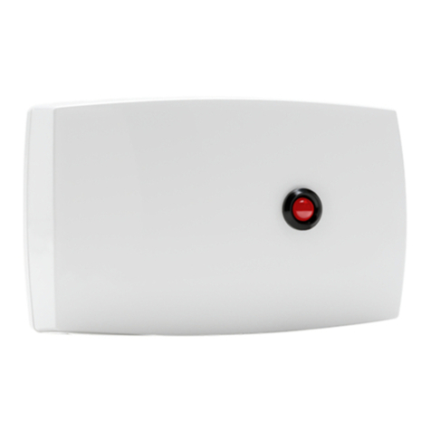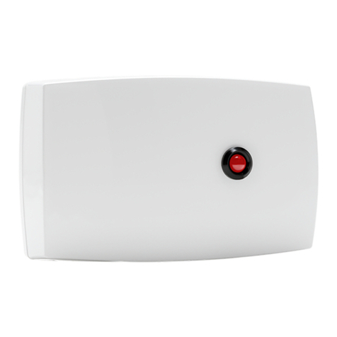
1118 Wireless Remote Indicator Light
Description
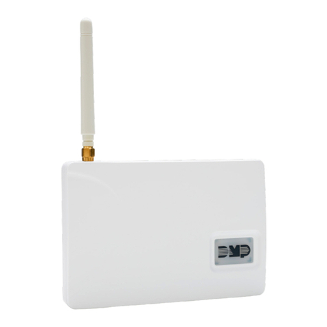
The 1118 Wireless Remote Indicator Light provides one remote LED indicator that can be used to visually notify the
user that a panic alarm has been activated. The 1118 is designed to operate on one CR123A battery or connect to an
optional 12 VDC power supply.
The 1118 operates with the XR500 or XR100 Series Command Processor™ panels version 119 using the 1100X Wireless
Receiver version 104.
What is Included
The 1118 includes the following:
• One 1118 Wireless Remote Indicator Light
• One 3.0V Lithium CR123A battery
• Hardware pack
• Serial number label
Optional items available:
• One Model 376 DC Power Supply
• One Model 378 Barrel Connector with Cord
Serial Number
For your convenience, an additional pre-printed serial number label is included. Prior to installing the indicator
light, record the serial number or place the pre-printed serial number label on the panel programming sheet. This
number is required during programming.
Programming the 1118 in the Panel
In Output Information enter the output number, output name, eight-digit serial number, and supervision time.
Specic output numbers are available for wireless. Output numbers 450-474 indicate whether the LED responds
within 15 seconds (slow response) or 480-499 indicate whether the LED responds within 1 second (fast response).
Program the 1118 Wireless Remote Indicator Light in Output Options as a Panic Alarm Output. Refer to the XR500
Series Programming Guide (LT-0679) or the XR100 Series Programming Guide (LT-0896).
Note: When a receiver is installed, powered down and powered up, the panel is reset, or programming is complete,
the supervision time is reset. If the receiver has been powered down for more than one hour, the 1118 may take
up to an additional hour to send a supervision message unless tripped, tampered, or powered up. This operation
extends battery life. A missing message may display on the keypad until the supervision message is sent.
Selecting the Proper Location (LED Survey Operation)
The 1118 provides a survey capability to allow one person to conrm communication with the receiver while the
cover is removed. The 1118 PCB Red Survey LED (see Figure 2) turns on whenever data is sent to the receiver then
immediately turns off when the receiver acknowledgement is received. Pressing the tamper switch is a convenient
way to send data to the receiver to conrm operation. When the 1118 does not receive an acknowledgement from
the receiver, the survey LED remains on for about 8 seconds to let you know communication is not established.
Communication is also faulty when the LED ashes multiple times in quick succession. Relocate the 1118 or
receiver until the LED immediately turns off indicating the 1118 and receiver are communicating properly. Proper
communication between the 1118 and receiver is veried when for each press or release of the tamper switch, the
LED blinks immediately on and immediately off. Repeat this test to conrm ve separate consecutive LED blinks.
Any indication otherwise means proper communication has not been established.
1118 Indicator Light Operation
When a Panic Alarm is sent, the indicator light is on steady for ve (5) minutes and then turns off. When a Panic
Test is sent to the 1118 from the 1100 Series Receiver, the indicator light ashes quickly for ve (5) minutes and then
turns off.
Squeeze to
Remove Cover
Squeeze to
Remove Cover
Power Supply
Plug Location
Red Remote
Indicator Light
Figure 1: 1118 Wireless Remote Indicator Light
INSTALLATION GUIDE
